


I. INTRODUCTION
Transmission lines (TLs) are essential components in modern telecommunication units, being used to connect antennas to transmitters and receivers, for impedance matching in mixers and amplifiers, or as resonant elements in oscillators and filters [Reference Pozar1]. When the electrical wavelengths are shorter than or comparable to the physical dimensions of a network, the length becomes important and TL theory should be applied instead of the standard circuit analysis. Thus, high-frequency TLs can be defined as TLs that are designed to carry electromagnetic waves whose wavelengths are shorter than or comparable to the length of the line. The left-handed (LH) TL structures with lower loss and wider bandwidth have led to the development of the novel microwave devices, such as new types super-lenses [Reference Sanada, Caloz and Itoh2], microwave components [Reference Lin, Caloz and Itoh3, Reference Sanada, Caloz and Itoh4], and leaky-wave antennas [Reference Liu, Caloz and Itoh5] and etcetera. In fact, a purely LH TL is not physical and can never be realized because of the parasitic effects. The metamaterials (MTMs) with LH properties have inevasible right-handed (RH) properties, known as composite right/left-handed (CRLH) MTMs. During the past years, CRLH materials made by inserting periodic inclusions [Reference Lai, Caloz and Itoh6] with dimensions smaller than the guided wavelength, p ≪ λ g , have attracted considerable attention in view of minimizing antenna size [Reference Jofre, Cetiner and De Flaviis7], which may lead to the development of new applications.
In this paper, we have proposed wideband MTM engraved plate antennas with ultra-compact size for wireless applications and today's requirements. In design processes of the proposed antennas, we have suggested and utilized of the new methodologies for enhancement of the antennas bandwidth and their radiation properties based on applying of the new types of inductors and capacitors with their standard dimensions. Also, we have employed MTM-TLs and the standard engraved plate techniques for antennas size reduction, so that these methods are introduced in the following.
The paper is categorized as follows. In Section II, we will be furnished a brief introduction to CRLH MTM antennas, their properties, and how they compare to conventional antennas. In Section III, two MTM engraved plate antennas, which have broader bandwidth and superior radiation properties with smaller size in comparison to other conventional antennas are proposed, designed, and fabricated. Sections IV and V consist of the simulated results, the measured data and the antennas characteristics, and the reasons to prove the accuracy of the suggested methods. Benefits of the proposed CRLH antennas are explained in Section VI, and finally discussion and conclusion are raised in Section VII.
II. CRLH MTM ANTENNAS
The propagation of electromagnetic waves in most materials obeys the right-handed rule for the E, H, and β vector fields, where E is the electrical field, H is the magnetic field, and β is the wave vector. The phase velocity is in the same direction of the signal energy propagation (group velocity), i.e., v p v g or v p v g > 0. The refractive index is a positive number. Such materials are “right handed” (RH). Unlike RH materials, MTMs can exhibit a negative refractive index with permittivity ε and permeability μ being simultaneously negative (ε and μ < 0. Their phase velocity direction is opposite to the direction of the signal energy propagation, i.e.; v p − v g or v p v g < 0, where the relative directions of the E, H, and β vector fields follow the LH rule. Thus, MTMs are also called “left handed” (LH) materials. Since no MTM exists naturally, it can only formed by an artificial structure. When designed with a structural average unit cell size p much smaller than the wavelength of the electromagnetic energy guided by the MTM (p ≪ λ g ), the MTM can behave like a homogeneous medium to the guided electromagnetic energy. Many MTMs exhibit LH and RH behavior and thus are CRLH MTMs. A CRLH MTM can behave like an LH MTM at low-frequency range (ω < ω0 or β < 0) and an RH material at high-frequency range (ω > ω0 or β > 0), as ω 0 is defined transmission frequency between LH and RH regions, which happen at β = 0, (1). The behavior of both LH and RH mode propagation at different frequencies can be easily addressed in a simple dispersion diagram, as shown in Fig. 1. The dispersion curve on the β > 0 side is the RH mode, whereas the dispersion curve on the β < 0 side is the LH mode [Reference Caloz and Itoh8]. After calculation, the dispersion relation for a homogeneous CRLH TL, (p ≪ λ g ), is [Reference Lai, Caloz and Itoh6]:
 $$\eqalign{\beta \lpar \omega \rpar & = s\lpar \omega \rpar \sqrt {\omega ^2\, L_R C_R+\displaystyle{1 \over {\omega ^2\, L_L C_L }} - \left({\displaystyle{{L_R } \over {L_L }}+\displaystyle{{C_R } \over {C_L }}} \right)} \mathop \to \limits^{\omega=\omega _0 \; \leftrightarrow \beta \lpar \omega _0 \rpar =0} \cr & \omega _0=\displaystyle{1 \over {\root 4 \of {L_R \; C_R \; L_L \; C_L } }}\comma \;}$$
where
 $$s\lpar \omega \rpar =\left\{{\matrix{ { - 1} & {{\rm if}} & {\omega\lt \omega _{se}=\min \left({\displaystyle{1 \over {\sqrt {L_R C_L } }}\comma \; \displaystyle{1 \over {\sqrt {L_L C_R } }}} \right)\; } \cr 0 & {{\rm if}} & {\omega _{se}\lt \omega\lt \omega _{sh} } \cr {+1} & {{\rm if}} & {\omega\gt \omega _{sh}={\rm max}\left({\displaystyle{1 \over {\sqrt {L_R C_L } }}\comma \; \displaystyle{1 \over {\sqrt {L_L C_R } }}} \right)\; } \cr } } \right\}$$
with, series and shunt resonance frequencies:
 $$\omega _{se}=\displaystyle{1 \over {\sqrt {L_R C_L } }}\comma \;$$
 $$\omega _{sh}=\displaystyle{1 \over {\sqrt {L_L C_R } }}.$$

Fig. 1. Dispersion diagrams (in general or unbalanced case) for PRH, PLH, and CRLH TLs. The labels “RH” and “LH” indicate the RH and LH frequency branches, respectively. Comparison of the CRLH, PLH (β PLH), and PRH (β PRH) TLs for energy propagation along the +z-direction (ν g > 0).
The CRLH MTMs can be structured and engineered to exhibit electromagnetic properties that are tailored for the specific applications and can be used in applications where it may be difficult, impractical or infeasible to use other solutions. The small antennas are one of most important applications of the CRLH MTMs . An electrically large but physically small antenna can be designed using the CRLH while maintaining the same or better performances than conventional compact antennas [Reference Lee, Leong and Itoh9]. The CRLH-based antennas can also be made very broadband to support today's multi-band communication and wireless applications requirements.
III. DESIGN THEORY OF THE RECOMMENDED ENGRAVED PLATE ANTENNAS
The recommended antennas are based on the CRLH MTM-TL unit cells. These engraved plate antennas are designed, tooled, and made on FR_4 and Rogers_RT_Duroid5880 substrates with dielectric constants of 4.6 and 2.2, and 0.8 mm and 1.6 mm thicknesses, and also Tanδ = 0.001 and 0.0009, respectively. These antennas are based on simplified planar mushroom structure unit cells. The unit cells consist of host TLs with J- and I-shaped voids, which are engraved on the rectangular radiation patches and the spiral inductors connected to the ground plane through metallic via holes as act like series capacitances C L and shunt inductances L L , respectively. Even if we intentionally provide only series capacitance and shunt inductance, parasitic series inductance L R and shunt capacitance C R effects, increasing with increasing frequency, will unavoidably occur due to currents flowing in the metallization and voltage gradients developing between the metal patterns of the trace and the ground plane, which indicates that these inductance and capacitance cannot be ignored. Therefore, a purely LH-TL cannot exist physically. Hence, the CRLH model represents the most general MTM structure possible. The proposed antenna structures are excited by external port (i.e., port 1 or input signal) and their port 2 are matched to 50 Ω load impedance of the Surface-Mount Device (SMD) resistive component, which this SMD component occupies the space of 4.2 mm of the antenna area and through metallic via hole is connected to ground plane. The CRLH propagation along a given direction is modeled by the eight-lumped element circuit parameters, which are shown in Fig. 2. This model essentially exhibits a series capacitance C L and a shunt inductance L L (LH), corresponding to negative permeability and negative permittivity, respectively (5) and (6), but also includes a series inductance L R and a shunt capacitance C R (RH) associated with the magnetic and electric fluxes, respectively, intrinsic to any TL structures, and corresponding to positive permeability and permittivity, respectively (5) and (6). In addition to these four reactive parameters, one has the conventional lossy parameters R R and G R (RH), and the lossy parameters G L and R L (LH), which account for the dielectric loss associated with C L and the ohmic loss associated with L L , respectively (7) and (8), and which mostly represent radiation in antenna applications.
 $$\mu=\displaystyle{{Z\lpar \omega \rpar } \over {j\omega }}=L_R - \displaystyle{1 \over {\omega ^2 C_L }}\comma \;$$
 $$\varepsilon=\displaystyle{{Y\lpar \omega \rpar } \over {j\omega }}=C_R - \displaystyle{1 \over {\omega ^2\, L_L }}\comma \;$$
 $$Z\lpar \omega \rpar =j\left({\omega \lpar L_R+R_R \rpar - \displaystyle{1 \over {\omega \left({C_L+\displaystyle{1 \over {G_L }}} \right)}}} \right)\comma \;$$
 $$Y\lpar \omega \rpar =j\left({\omega \lpar L_L+R_L \rpar - \displaystyle{1 \over {\omega \left({C_R+\displaystyle{1 \over {G_R }}} \right)}}} \right).$$
In this paper, we have presented the new antennas that are fabricated by the novel approaches based on implementation of the useful capacitive and inductive components, which lead to extension of the antennas bandwidth and enhancement of their radiation properties, and also we have suggested a new theory based on employment of the standard engraved plate methodology and the CRLH MTM-TLs technology for downsizing of the antennas.

Fig. 2. Unit cell of the proposed antennas.
A) Wideband small engraved plate MTM J-formed antenna
In the antenna design, we have used of the new ways based on design of the practical capacitive and inductive elements for development the antenna bandwidth and its radiation characteristics to good satisfy the severe needs of modern commercial and industrial applications. These methods are; employment the smaller values of the loaded series capacitances, which with realization these smaller values by implementation of the engraved J-formed voids on the rectangular radiation patches with minimum their acceptable dimensions the antenna bandwidth is developed. This method expands the antenna bandwidth, so that a wideband antenna is provided with 9.3 GHz measured bandwidth, from 7.5 to 16.8 GHz, for Voltage Standing Wave Ratio (VSWR) < 2, which corresponds to 74.4% practical bandwidth. As well as, applying six unit cells, so that each one are composed of a J-shaped void accompanying a spiral inductor, which this inductor is constructed from a ring and through a metallic via hole with suitable dimension is connected to ground plane, the aperture efficiency of the antenna is extended, thus, the antenna radiation specifications are enhanced. The measured gains and radiation efficiencies of the antenna at the operating frequencies f = 7.5, 14.5, and 16.8 GHz are 0.1 dBi and 20%, 2.1 dBi and 44.3%, and 1.7 dBi and 32.6%, respectively.
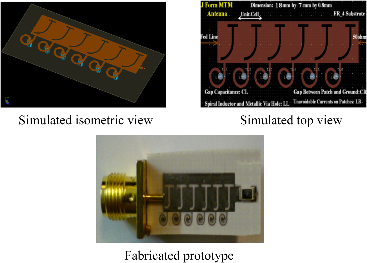
It should be noted that, in beside excellent bandwidth and radiation characteristics, for good satisfy the severe requirements of the portable devices such as mobile handsets, laptops, media players, modern communication transceivers, and so on, small size is a very important topic in the antenna design process. In this paper, the basic method to reduce the antenna dimension is carving a new geometry on a high dielectric substrate, which this carved geometry plays the role of the series capacitor and leads to reduction of the occupied area by the structure constructive components. As a result, using this method is provided a small antenna with broad bandwidth and good radiation characteristics. Figure 3 suggests that the standard engraved plate technique based on MTM CRLH-TL is used to the production of series capacitors (C L ), so that the engraved J-shaped voids on radiation patches are leading to a decrease in the antenna dimension. The presented antenna was designed, tooled and made on FR_4 substrate with ε r = 4.6, thickness of h = 0.8 mm and Tanδ = 0.001. The antenna is composed of six simplified planar mushroom structure unit cells with J-shaped geometries, each of which occupy the space of 2.3 × 7 × 0.8 mm3 or 0.057λ 0 × 0.175λ 0 × 0.02λ 0 in terms of the free-space wavelengths at the operational frequency f = 7.5 GHz of the antenna total area. The length, width and height of the antenna are 18, 7, and 0.8 mm or 0.45λ 0, 0.175λ 0, and 0.02λ 0, respectively. The proposed J-shaped antenna layout based on the CRLH-TL is shown in Fig. 3.

Fig. 3. Configuration of the engraved J-formed antenna structure composed of six unit cells.
B) Wideband small engraved plate MTM I-formed antenna with better performances
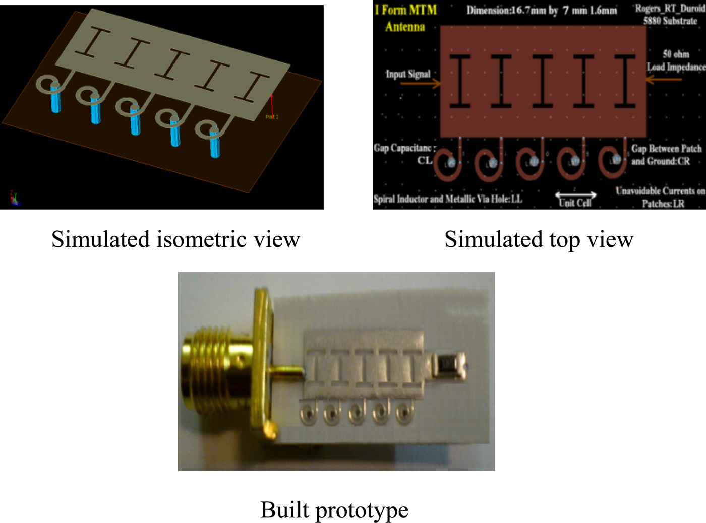
In this section, we have presented the engraved I-formed antenna structure that constructed of five unit cells with the expanded bandwidth and the improved radiation characteristics in comparison to the proposed J-formed antenna. The design processes and the general equivalent circuit models of both antennas are completely identical with each other, but their substrates, geometries and the number of unit cells are different and thereby the antennas have different layouts. Implementation of these suggested differences in the second antenna design lead to amplification the antenna bandwidth, and also another important point it is that the antenna has the ability to provide better radiation characteristics using the mentioned disputes. The antenna configuration is shown in Fig. 4.

Fig. 4. Layout of the engraved I-formed antenna structure composed of five unit cells.
As is evident in Fig. 4, for the bandwidth expansion and the radiation properties improvement, the antenna configuration has been changed than first antenna layout, meaning that the I-formed voids have been replaced with the J-formed voids. These I-formed voids perform the role of the series capacitors C L and thus lead to reduction of the antenna area. In addition, the number of unit cells and according to it the number of capacitive and inductive elements change in comparison to the J-formed antenna prototype. The mentioned variations have direct effect on the bandwidth and radiation characteristics of the antenna. This antenna covers 10.9 GHz measured bandwidth and can be utilized to frequency band from 7.7 to 18.6 GHz, which corresponds to 82.88% feasible bandwidth. Also, the ranges of the measured gains and radiation efficiencies of the I-shaped antenna are 1.15 dBi < G < 3.11 dBi and 30.24% < eff < 58.6%, respectively. The measured results demonstrate that the lowest gain and radiation efficiency of the antenna are 1.15 dBi and 30.24%, that occur at f = 7.7 GHz and the highest gain and efficiency are 3.11 dBi and 58.6%, which happen at f = 17.2 GHz. The antenna was designed, tooled and built on Rogers_RT_Duroid5880 substrate with ε r = 2.2, thickness of h = 1.6 mm and Tanδ = 0.0009. The physical size of the antenna is 0.428λ 0 × 0.179λ 0 × 0.041λ 0 in terms of the free-space wavelengths at the operational frequency f = 7.7 GHz, and its length, width and height are 16.7, 7 and 1.6 mm, respectively.
IV. SIMULATED RESULTS, MEASURED DATA AND DISCUSSIONS OF THE PROPOSED ANTENNAS
The antennas were designed, tooled and made on FR_4 and Rogers_RT_Duroid5880 substrates with ε r = 4.6 and 2.2, thickness of h = 0.8 and 1.6 mm and Tanδ = 0.001 and 0.0009, respectively. Each unit cell of the J- and I-shaped antennas occupy the space of 2.3 × 7 × 0.8 mm3 and 2.5 × 7 × 1.6 mm3 or 0.057λ 0 × 0.175λ 0 × 0.02λ 0 and 0.064λ 0 × 0.179λ 0 × 0.041λ 0 in terms of the free-space wavelengths of the antennas total area and overall size of the antennas are 18 × 7 × 0.8 mm3 and 16.7 × 7 × 1.6 mm3, or 0.45λ 0 × 0.175λ 0 × 0.02λ 0 and 0.428λ 0 × 0.179λ 0 × 0.041λ 0, respectively.
Figure 5 shows the simulated and measured return losses of the recommended antennas. So that is shown in this figure, the simulated bandwidths (S 11 <−10 dB) of the engraved J- and I-shaped antennas are 13.5 GHz (4.9–18.4 GHz) and 14.3 GHz (6.5–20.8 GHz), that correspond to 115.87 and 104.76% simulated bandwidths, respectively. Also, the measured bandwidths of these antennas are equal to 9.3 GHz (7.5–16.8 GHz) and 10.9 GHz (7.7–18.6 GHz), which correspond to 74.4 and 82.88% practical bandwidths, respectively.
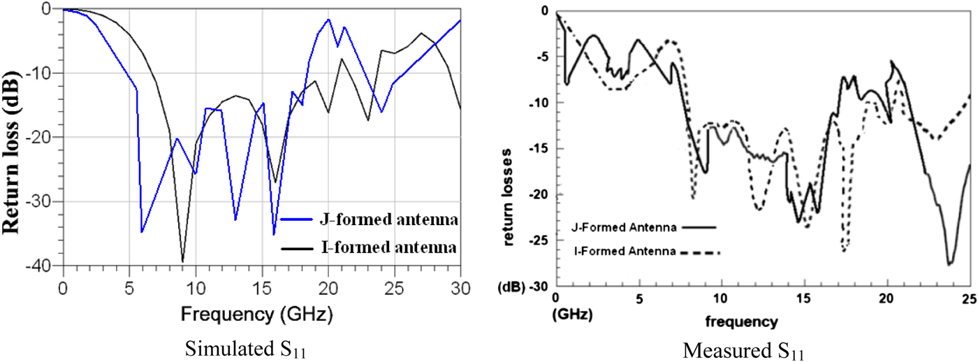
Fig. 5. Reflection coefficients (S 11 <−10 dB) of the proposed antennas.
For the J-shaped antenna, the simulated radiation gains and efficiencies at 7.5, 14.5, and 16.8 GHz are 0.6 dBi and 27.3%, 3 dBi and 50.1%, and 2.4 dBi and 38.2%, respectively, and the measured values of these parameters at same frequencies are 0.1 dBi and 20%, 2.1 dBi and 44.3%, and 1.7 dBi and 32.6%, respectively. The simulated and measured radiation patterns of the J-formed antenna are shown in Fig. 6.

Fig. 6. Simulated and measured two-dimensional (2D) radiation gains patterns of the engraved J-formed antenna composed of six unit cells in elevation plane (Φ = 0°) at the operational frequencies.
Also, for the I-formed antenna the simulated radiation gains and efficiencies at 7.7, 17.2, and 18.6 GHz are 1.7 dBi and 36.3%, 3.8 dBi and 64.8%, and 3.1 dBi and 55.2%, respectively, and the measured values of these parameters at same frequencies are 1.15 dBi and 30.24%, 3.11 dBi and 58.6%, and 2.7 dBi and 49.3%, respectively. The simulated and measured radiation patterns of the I-formed antenna are displayed in Fig. 7.

Fig. 7. Simulated and measured two-dimensional (2D) radiation gains patterns of the engraved I-formed antenna constructed of five unit cells in elevation plane (Φ = 0°) at operational frequencies.
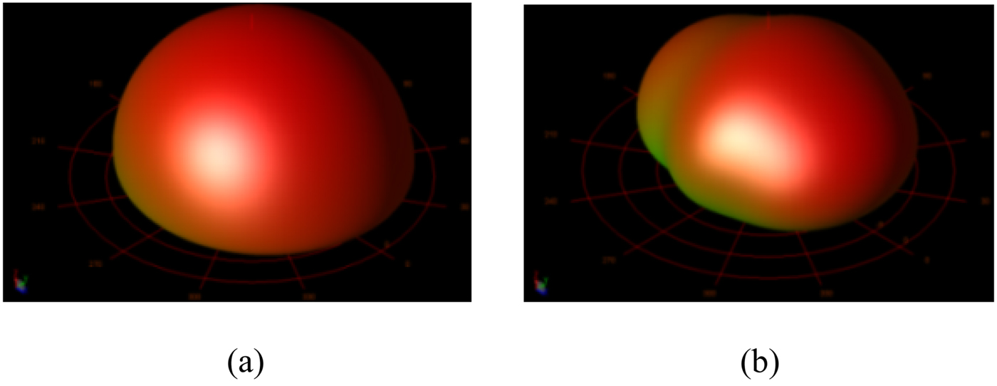
In addition to two-dimensional (2D) radiation patterns, the simulated three-dimensional (3D) radiation gains patterns of these antennas are shown in Fig. 8.

Fig. 8. Simulated three-dimensional (3D) radiation gains patterns of the proposed antennas in elevation plane (Φ = 0°) at operation frequencies. (a) for the J-formed antenna at f = 16 GHz, and (b) for the I-shaped antenna at 18 GHz.
As can be inferred from Figs 6–8, the radiation patterns have unidirectional characteristics. The simulated results were obtained using Agilent ADS full-wave simulator.
As evident from the results, the simulated results and the measured data of both antennas have little differences towards one another. The reason for these differences it is that, both antennas have been simulated on an infinite ground plane layer, but unlike the simulation processes, due to size limitations for implementation the antennas with small dimensions and the fabrication limits, the manufacturing procedures were conducted on a finite ground plane layer, therefore the fabricated antennas have a limited ground plane layer. For this reason, the simulated results and measured data have a slightly differences relative to each other.
V. CHECK OF CORRECTNESS OF THE PRESENTED METHODS
In the introduced antennas design, we have used of new methods to reduce the antennas size, expansion of their bandwidth, and enhancement of their radiation properties. These methods include: employment of the MTM technology, the engraved voids with new geometries, the smaller values of the loaded series capacitances (C L ) that these smaller values were realized by implementation the engraved voids with minimum of acceptable dimensions, the suitable inductive, and capacitive components such as spiral inductors connected to the ground plane through metallic via holes and empty spaces capacitors. It should also be noted that, from the impact of 50 Ω SMD resistive component on the antenna performances cannot be ignored, but this effect in front the effects of the proposed methods is negligible. To prove this claim, in this section two other antennas are designed, so that the recommended methods are applied in the design procedures of these antennas. The new antennas structure is quite similar to the previous antennas structure, but to better illustrate the effects of the presented methods the new structures are composed from the more cells, and also in these structures to matching is used of 20 Ω SMD resistive component rather than 50 Ω.
A) J-formed antenna constructed of eight unit cells
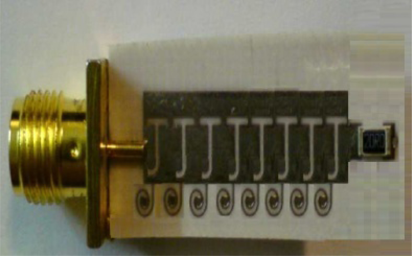
This antenna is fabricated of eight J-formed unit cells. The antenna design process is thoroughly similar to design process of the J-formed antenna constructed of six unit cells. Here, in addition to the effect of increasing the number of unit cells on the antenna size, with increasing the number of capacitive and inductive components that are generated by the engraved J-formed voids and the spiral inductors and perform the roles of the series LH capacitances (C L ) and shunt LH inductances (L L ), the LH effects have been increased. Growth of the LH nature leads to improvement in the antenna performances. This antenna prototype is exhibited in Fig. 9.

Fig. 9. Prototype of the J-formed antenna made of eight unit cells.
Overall size of this antenna is 22.6 × 7 × 0.8 mm3 or 0.564λ 0 × 0.175λ 0 × 0.02λ 0 in terms of the free-space wavelengths at the operating frequency f = 7.5 GHz. Return loss (S 11 <−10 dB) of the antenna is shown in Fig. 10. As this figure suggests, the J-formed antenna constructed of eight unit cells can be used for frequency band from 7.25 to 17.8 GHz in measurement, which corresponds to 84.23% practical bandwidth.

Fig. 10. Reflection coefficients (S 11 <−10 dB) of the J- and I-shaped antennas, each of which are fabricated from eight and seven unit cells, respectively.
By adding two unit cells and in the resulting increase in the structure size, the antenna effective aperture is extended, and as a result the radiation characteristics of the antenna markedly are improved. The measured radiation gains and efficiencies at the operating frequencies f = 7.5, 14.5, and 16.8 GHz are 0.8 dBi and 23%, 2.35 dBi and 48.2%, and 1.85 dBi and 37.1%, respectively. The radiation patterns at the mentioned frequencies are depicted in Fig. 11. As is known of this figure, the measured radiation patterns are unidirectional.

Fig. 11. Measured radiation patterns of the J-formed antenna constructed of eight unit cells in elevation plane (Φ = 0°) at the operational frequencies.
B) I-shaped antenna consist of seven unit cells
Increase the number of unit cells leads to increasing of the size and number of the shunt inductive (L L ) and series capacitive (C L ) components, thus the LH effects are increased, which are leading to a significant development in the bandwidth and radiation properties. So that in this case, an appropriate increase in the structure size is acceptable. Formation of the I-shaped antenna made of seven unit cells is displayed in Fig. 12.
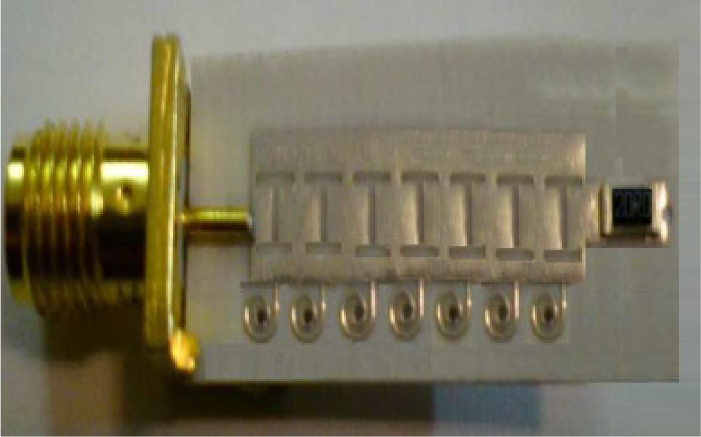
Fig. 12. Formation of the I-shaped antenna comprised of seven unit cells.
The length, width, and height of this antenna are 21.7, 7, and 1.6 mm or 0.556λ 0, 0.179λ 0, and 0.041λ 0 in terms of the free-space wavelengths at f = 7.7 GHz, respectively. Also, the I-shaped antenna constructed of seven unit cells has 12.05 GHz measured bandwidth from 7.8 to 19.85 GHz, which is related to 87.16% feasible bandwidth. The reflection coefficients (S 11 <−10 dB) of the recent antennas are plotted in Fig. 10.
In addition to the antenna bandwidth, other important specifications of the antenna that are affected by increasing the number of unit cells and the structure length are radiation characteristics. The measured gains and radiation efficiencies of the I-formed antenna made of seven unit cells at the operational frequencies f = 7.7, 17.2, and 18.6 GHz are 1.2 dBi and 32.4%, 3.4 dBi and 68.1%, and 2.86 dBi and 53.2%, respectively. The measured radiation patterns of this antenna at the above frequencies are displayed in Fig. 13. As can be inferred of this figure, the radiation patterns have unidirectional specifications.

Fig. 13. Measured radiation patterns of the I-shaped antenna composed of seven unit cells in elevation plane (Φ = 0°) at the operating frequencies.
From the obtained results it is concluded that, with increasing the number of unit cells, in other words increase the structures length and consequently increase the number of capacitive and inductive components, i.e.; the carved voids with new geometries and the spiral inductors accompanying their optimized dimensions the LH nature at the desired frequencies is enhanced and as a result the antennas with better performances have been achieved. Hence it can be deduced that, passable variations in the number of unit cells, the structures length and the dimensions of the engraved voids, and the spiral inductors have significant impacts on the antenna performances that are strong reasons to prove the correctness of the presented methods.
To validate the design processes, the proposed antennas were compared with several conventional antennas and their specifications were summarized in Table 1.
Table 1. Specifications of some of the conventional antennas in comparison to the presented antennas. Attention: the labels P, D, G, B, E, 6UC, 5UC, 8UC, and 7UC refer to the parameters, dimension, gain (dBi), bandwidth (GHz and %), efficiency (%), J-formed antenna constructed of six unit cells, I-formed antenna made of five unit cells, J-shaped antenna with eight unit cells, and I-shaped antenna with seven unit cells, respectively. The measured gains and radiation efficiencies of the J-formed antennas have been achieved at 7.5, 14.5, and 16.8 GHz, respectively, and same parameters for I-formed antennas are obtained at 7.7, 17.2, and 18.6 GHz, respectively.

VI. BENEFITS OF THE SUGGESTED ANTENNAS BASED ON CRLH MTM-TLS
The proposed CRLH MTM antennas are wideband, low-profile, and ultra-miniature on an engraved circuit board, and consist of the superior radiation performances. In fact, according to Table 1, the proposed CRLH-based antennas have broader bandwidth and smaller dimension than conventional antennas while offering better radiation performances. Furthermore, unlike conventional 3D antennas, which must be designed, tooled, and fabricated as a complex metal-and-plastic assembly, the proposed antennas that are shown in Figs 3, 4, 9, and 12 are easily designed, tooled, and made in 3D layouts. The copper artwork is engraved directly on an engraved circuit board using standard engraved circuit board manufacturing techniques. This offers manufacturers faster time to market and reduced bills-of-materials due to the simplified design. It also offers a greatly reduced need for fabrication and assembly of the antennas components.
These MTM structures have the ability to concentrate electromagnetic fields and currents near antenna structures, instead of spreading them along the antenna ground, causing higher coupling between antenna components. This allows small antennas to be realized with minimal mutual coupling, to be able to decorrelate multipath cells in small implementations. The typical CRLH unit cell consists of a feed line that is electromagnetically coupled to a metallic patch, an engraved void with special geometry and a spiral inductor that is connected to the ground plane through a metallic via hole. The feed line through the small carved voids excites the CRLH unit cells. Typically, the antennas are matched to a port with 50 or 20 Ω input impedances. The antennas size, their bandwidth, radiation specifications, and resonant frequencies can be controlled by acceptable changing the number of unit cells and the antennas length, the dimensions of the spiral inductors and the engraved voids, the distance between the antenna components and the ground and also antenna components toward each other, and various other dimensions and layouts.
The presented antennas based on CRLH MTM-TLs can be used for frequency bands from 7.5 to 16.8 GHz, 7.7 to 18.6 GHz, 7.25 to 17.8 GHz, and 7.8 to 19.85 GHz, which correspond to 74.4, 82.88, 84.23, and 87.16% applicable bandwidths, respectively. Therefore, the proposed wideband small engraved plate antennas based on CRLH MTM TLs can be practical and feasible for commercial and industrial applications, today's electromagnetic requests, modern wireless telecommunication systems, radar implementations, location tracing, and data transmissions, that were approved by federal communications commission in 2002 [10].
VII. CONCLUSION
In this paper, we have introduced a new idea for development of the antennas bandwidth and improve their radiation characteristics based on implementation the appropriate capacitive and inductive components with new geometries and the optimized dimensions, and also a new concept to the antennas size reduction based on MTM design technology and the standard engraved plate methodology is presented. All obtained results demonstrate that the proposed CRLH MTM antennas have wider bandwidth, smaller size, and superior radiation properties in comparison to other conventional antennas. These antennas have the advantages of very small size, wide bandwidth, lightweight, high gain and efficiency, unidirectional radiation patterns, simple implementation, and low cost. The simulated and measured results suggest that the proposed antennas are potential candidates for use in the electromagnetic requests, modern wireless telecommunication systems, radar implementations, location tracing, and transceivers.
ACKNOWLEDGEMENTS
The author would like to express his sincere thanks to Iran Telecommunication Research Center (ITRC) with Contract number of 6987/500/T, the Microwave and Millimeter Wave Laboratory of the Amirkabir University of Technology (Tehran Polytechnic) and the antenna laboratory of the K. N. Toosi University of Technology.
 Mohammad Alibakhshi Kenari was born in February 1988 at Iran. He received the B.S. and M.S. degrees in Communication Engineering from the University of Najafabad at Iran, in February 2009 and the University of Shahid Bahonar at Iran in February 2013, respectively. His research areas include microwave and millimeter wave circuits, small and wideband antennas, metamaterial applications, RF technologies, embedded systems, and wireless communication systems.


Target article
Retraction Notice
Related commentaries (6)
A new compact UWB traveling-wave antenna based on CRLH-TLs for embedded electronic systems
Designing an ultra-wideband electromagnetic waves receiver with new architecture for RF and wireless applications
Introducing the new wideband small plate antennas with engraved voids to form new geometries based on CRLH MTM-TLs for wireless applications
Miniaturized printed monopole antenna with applying the modified conductor-backed plane and three embedded strips based on CPW for multi-band telecommunication devices
Modeling and constructing the microstrip notch-loaded rectangular S-shaped patch antennas using L-strip feeding for multi-band frequency performances in the recent wireless telecommunication systems
Significant measureable development of inductance gain per unit of space in loop fractals