


1 Introduction
In applications and natural settings, gas–liquid interfaces are often found covered with particulate material. Fouling of gas–liquid interfaces can occur in unsaturated porous media or environmental bubbly flows, owing to the presence of fine grains and biocolloids that adhere to the fluid interface (Weber, Blanchard & Syzdek Reference Weber, Blanchard and Syzdek1983; Shang, Flury & Deng Reference Shang, Flury and Deng2009). In applications, rigid particles or globular proteins are often added as surface-active agents to change the mechanical properties of the interface or induce stabilisation against coalescence (Tambe & Sharma Reference Tambe and Sharma1994; Binks Reference Binks2002; Stancik, Kouhkan & Fuller Reference Stancik, Kouhkan and Fuller2004).
As for molecular surfactants, the presence of the embedded solid particles alters the boundary conditions at a fluid interface; for experimental evidence, see e.g. Hunter et al. (Reference Hunter, Pugh, Franks and Jameson2008) and Kotula & Anna (Reference Kotula and Anna2012); for a theoretical analysis, see Deemer & Slattery (Reference Deemer and Slattery1978). These boundary conditions for the bulk fluid are to be applied to the particle-laden fluid interface, i.e. the composite interface formed by the particles and the fluid interface in which the particles are embedded. In the absence of mass transfer effects, the no-penetration condition at the particle-laden interface is expected to hold with good accuracy. However, the boundary condition for the velocity tangential to the particle-laden fluid interface must be modified to account for the additional resistance caused by the presence of the particles to the motion of the adjacent fluid layers. This additional resistance is expected to be particularly significant when a significant velocity difference occurs between the particle-laden fluid interface and the adjacent fluid (figure 1).
In this paper we simulate shear flow past a gas–liquid interface containing a monolayer of spherical particles, for the case in which the particle-laden fluid interface is flat and the monolayer is stationary (or moving with constant velocity if a change of reference frame is accounted for). All the simulations are carried out in the Stokes flow limit. The simulation results allow one to gain insights into the dependence of the slip length parameter appearing in a partial slip boundary condition for the particle-laden interface on the macroscopic flow variables and particle distribution. Such a boundary condition could be applied to problems related to froth flotation (Subrahmanyam & Forssberg Reference Subrahmanyam and Forssberg1988), solid stabilised foams and emulsions (Horozov Reference Horozov2008; Martinez et al. Reference Martinez, Rio, Delon, Saint-Jalmes, Langevin and Binks2008) and spray drying (Tsapis et al. Reference Tsapis, Dufresne, Sinha, Riera, Hutchinson, Mahadevan and Weitz2005).

Figure 1. Examples of flow problems involving gas–liquid particle-laden interfaces where significant particle–fluid velocity slip is expected: (a) a rising particle-coated bubble (Weber et al. Reference Weber, Blanchard and Syzdek1983); (b) liquid drainage in particle-laden thin films (Stancik et al. Reference Stancik, Kouhkan and Fuller2004; Hunter et al. Reference Hunter, Pugh, Franks and Jameson2008; Bournival, Ata & Wanless Reference Bournival, Ata and Wanless2015); and (c) formation of particle-coated bubbles in a microfluidic device (Subramaniam, Abkarian & Stone Reference Subramaniam, Abkarian and Stone2005; Kotula & Anna Reference Kotula and Anna2012).
Recently, the statics and dynamics of particles embedded in fluid interfaces has been subject to increasing interest. Singh & Joseph (Reference Singh and Joseph2005) studied the equilibrium condition for particles supported by surface tension at a horizontal fluid interface, as a function of particle weight and contact angle. Under the effect of gravity, particles induce a distortion of the fluid interface whose amplitude is proportional to the magnitude of the particle weight. For particles in the size range of typical colloids (
 $a<10~\unicode[STIX]{x03BC}\text{m}$
), the particle weight is orders of magnitude smaller than the capillary force on the particle. As a consequence, the interface around the particle can be considered locally flat and unaffected by the gravitational force acting on the particle. This notion can be generalised to non-horizontal particle-laden interfaces. For curved particle-laden fluid interfaces, the composite interface can be considered locally flat if the particle radius is small in comparison to the radius of curvature of the particle-laden interface. For a locally flat interface, the degree of protrusion of a solid particle in the liquid phase is a function of only the contact angle
$a<10~\unicode[STIX]{x03BC}\text{m}$
), the particle weight is orders of magnitude smaller than the capillary force on the particle. As a consequence, the interface around the particle can be considered locally flat and unaffected by the gravitational force acting on the particle. This notion can be generalised to non-horizontal particle-laden interfaces. For curved particle-laden fluid interfaces, the composite interface can be considered locally flat if the particle radius is small in comparison to the radius of curvature of the particle-laden interface. For a locally flat interface, the degree of protrusion of a solid particle in the liquid phase is a function of only the contact angle
 $\unicode[STIX]{x1D703}_{c}$
and the particle radius (Rapacchietta & Neumann Reference Rapacchietta and Neumann1977).
$\unicode[STIX]{x1D703}_{c}$
and the particle radius (Rapacchietta & Neumann Reference Rapacchietta and Neumann1977).
The drag forces on single spheres embedded in fluid–fluid interfaces has been studied by several authors. For gas–liquid interfaces, the drag force is a monotonic function of the degree of protrusion of the particle in the liquid phase (Petkov et al.
Reference Petkov, Denkov, Danov, Velev, Aust and Durst1995; Danov, Dimova & Pouligny Reference Danov, Dimova and Pouligny2000; Fischer, Dhar & Heinig Reference Fischer, Dhar and Heinig2006). When
 $\unicode[STIX]{x1D703}_{c}=90^{\circ }$
, owing to symmetry, the drag on an isolated sphere in a uniform flow is exactly half the Stokes drag for a fully immersed sphere. A particle embedded in a gas–liquid interface and subject to a shear flow will also experience a hydrodynamic torque and may rotate (Pozrikidis Reference Pozrikidis2007). However, effects due to rotation, which depend on the shear rate, are expected to be subdominant with respect to those due to relative translation between the particle and the surrounding fluid; for small particles contact line pinning may prevent rotation completely, and this is a situation often found in practice (Dörr et al.
Reference Dörr, Hardt, Masoud and Stone2016). Only a few studies have investigated the hydrodynamics of multiple interfacial particles. These studies are typically concerned with the dynamics of small clusters of particles (Singh & Joseph Reference Singh and Joseph2005; Dani et al.
Reference Dani, Keiser, Yeganeh and Maldarelli2015), or the macroscopic effect of the collective motion of many particles on the dynamics of liquid–liquid interfacial structures (Frijters, Günther & Harting Reference Frijters, Günther and Harting2012). To the best of our knowledge, the interfacial drag on multiple particles subject to shear flow and the characteristics of the slip flow for this flow configuration have not been considered in the literature.
$\unicode[STIX]{x1D703}_{c}=90^{\circ }$
, owing to symmetry, the drag on an isolated sphere in a uniform flow is exactly half the Stokes drag for a fully immersed sphere. A particle embedded in a gas–liquid interface and subject to a shear flow will also experience a hydrodynamic torque and may rotate (Pozrikidis Reference Pozrikidis2007). However, effects due to rotation, which depend on the shear rate, are expected to be subdominant with respect to those due to relative translation between the particle and the surrounding fluid; for small particles contact line pinning may prevent rotation completely, and this is a situation often found in practice (Dörr et al.
Reference Dörr, Hardt, Masoud and Stone2016). Only a few studies have investigated the hydrodynamics of multiple interfacial particles. These studies are typically concerned with the dynamics of small clusters of particles (Singh & Joseph Reference Singh and Joseph2005; Dani et al.
Reference Dani, Keiser, Yeganeh and Maldarelli2015), or the macroscopic effect of the collective motion of many particles on the dynamics of liquid–liquid interfacial structures (Frijters, Günther & Harting Reference Frijters, Günther and Harting2012). To the best of our knowledge, the interfacial drag on multiple particles subject to shear flow and the characteristics of the slip flow for this flow configuration have not been considered in the literature.
The flow past a stationary monolayer of spheres embedded in a gas–liquid interface bears obvious similarities to flow past a microstructured superhydrophobic surface. In both cases one can define a composite surface composed of free-slip and no-slip ‘patches’. From the point of view of continuum modelling, i.e. considering flow variables on a scale much larger than the particles, the boundary condition at such a composite surface is expected to be a linear combination of the boundary conditions that are appropriate for the solid and fluid regions. Composite free-slip/no-slip interfaces indeed have been successfully modelled through a Navier slip boundary condition
 $$\begin{eqnarray}\unicode[STIX]{x1D706}\langle \dot{\unicode[STIX]{x1D6FE}}\rangle _{s}=\langle u\rangle _{s},\end{eqnarray}$$
where
 $\langle \dot{\unicode[STIX]{x1D6FE}}\rangle _{s}$
is the bulk shear rate at the interface,
$\langle \dot{\unicode[STIX]{x1D6FE}}\rangle _{s}$
is the bulk shear rate at the interface,
 $\langle u\rangle _{s}$
is the interfacial slip velocity and
$\langle u\rangle _{s}$
is the interfacial slip velocity and
 $\unicode[STIX]{x1D706}$
is the slip length. For superhydrophobic surfaces, the dependence of
$\unicode[STIX]{x1D706}$
is the slip length. For superhydrophobic surfaces, the dependence of
 $\unicode[STIX]{x1D706}$
on the geometry of the microstructure has been studied extensively (Rothstein Reference Rothstein2010):
$\unicode[STIX]{x1D706}$
on the geometry of the microstructure has been studied extensively (Rothstein Reference Rothstein2010):
 $\unicode[STIX]{x1D706}$
is a function of the size of the microstructural elements, the area fraction covered by the solid and the arrangement of the microstructural elements in the slip plane (Lauga & Stone Reference Lauga and Stone2003; Sbragaglia & Prosperetti Reference Sbragaglia and Prosperetti2007; Ybert et al.
Reference Ybert, Barentin, Cottin-Bizonne, Joseph and Bocquet2007; Ng & Wang Reference Ng and Wang2009). In this paper we investigate the suitability of boundary condition (1.1) for flat particle-laden gas–liquid interfaces; results for flat interfaces are relevant to flow situations in which the radius of curvature of the interface is much larger than the characteristic particle radius. We characterise the slip flow past a monolayer of stationary spherical particles for a specific contact angle,
$\unicode[STIX]{x1D706}$
is a function of the size of the microstructural elements, the area fraction covered by the solid and the arrangement of the microstructural elements in the slip plane (Lauga & Stone Reference Lauga and Stone2003; Sbragaglia & Prosperetti Reference Sbragaglia and Prosperetti2007; Ybert et al.
Reference Ybert, Barentin, Cottin-Bizonne, Joseph and Bocquet2007; Ng & Wang Reference Ng and Wang2009). In this paper we investigate the suitability of boundary condition (1.1) for flat particle-laden gas–liquid interfaces; results for flat interfaces are relevant to flow situations in which the radius of curvature of the interface is much larger than the characteristic particle radius. We characterise the slip flow past a monolayer of stationary spherical particles for a specific contact angle,
 $\unicode[STIX]{x1D703}_{c}=90^{\circ }$
, and investigate the dependence of
$\unicode[STIX]{x1D703}_{c}=90^{\circ }$
, and investigate the dependence of
 $\unicode[STIX]{x1D706}$
on relevant parameters for two cases: a square array, and a reticulated array in which the particles are distributed according to a mesh-like arrangement. These two cases are idealisations of two limiting cases found in practice (Aveyard et al.
Reference Aveyard, Clint, Nees and Paunov2000) of monolayers constituted by particles well dispersed in the interface due to interparticle repulsion, and monolayers constituted by particles forming two-dimensional percolating networks due to particle–particle attraction, respectively.
$\unicode[STIX]{x1D706}$
on relevant parameters for two cases: a square array, and a reticulated array in which the particles are distributed according to a mesh-like arrangement. These two cases are idealisations of two limiting cases found in practice (Aveyard et al.
Reference Aveyard, Clint, Nees and Paunov2000) of monolayers constituted by particles well dispersed in the interface due to interparticle repulsion, and monolayers constituted by particles forming two-dimensional percolating networks due to particle–particle attraction, respectively.
The neutrally wetting case
 $\unicode[STIX]{x1D703}_{c}=90^{\circ }$
studied here has practical relevance. In applications it is indeed desirable to have a contact angle close to
$\unicode[STIX]{x1D703}_{c}=90^{\circ }$
studied here has practical relevance. In applications it is indeed desirable to have a contact angle close to
 $90^{\circ }$
, as this limiting angle gives the strongest adhesion of the particle to the interface against desorption in either of the two adjacent fluids (Binks & Horozov Reference Binks and Horozov2006).
$90^{\circ }$
, as this limiting angle gives the strongest adhesion of the particle to the interface against desorption in either of the two adjacent fluids (Binks & Horozov Reference Binks and Horozov2006).
2 Problem formulation

Figure 2. We simulate a stationary monolayer of particles half-immersed in a flat gas–liquid interface. The fluid is sheared by a moving wall located at a distance
 $d$
from the monolayer and moving with constant velocity
$d$
from the monolayer and moving with constant velocity
 $U$
. For large values of
$U$
. For large values of
 $d$
our results converge to the asymptotic limit in which the flow near the monolayer depends on the macroscopic shear rate induced by the moving wall, but not on
$d$
our results converge to the asymptotic limit in which the flow near the monolayer depends on the macroscopic shear rate induced by the moving wall, but not on
 $d$
directly.
$d$
directly.
We model shear flow past a stationary monolayer of spherical particles of radius
 $a$
embedded in a flat air–liquid interface for a contact angle of
$a$
embedded in a flat air–liquid interface for a contact angle of
 $90^{\circ }$
(figure 2). The fluid is set in motion by a flat wall located at a distance
$90^{\circ }$
(figure 2). The fluid is set in motion by a flat wall located at a distance
 $d$
from the monolayer and translating with velocity
$d$
from the monolayer and translating with velocity
 $U$
with respect to the spheres. For large values of
$U$
with respect to the spheres. For large values of
 $d$
, the liquid can be considered to be bounded by the particle-laden interface only. In this limit we obtain asymptotic results that depend on the macroscopic bulk shear rate, and not on
$d$
, the liquid can be considered to be bounded by the particle-laden interface only. In this limit we obtain asymptotic results that depend on the macroscopic bulk shear rate, and not on
 $d$
directly.
$d$
directly.
To simulate the flow configuration described above, we employ an expedient that allows us to use a fast solver for finite size particles in bulk flows to simulate a particle-laden gas–liquid interface. We simulate the flow past a monolayer of spherical particles completely embedded in the liquid and placed at the centre of a two-dimensional channel. The channel walls translate parallel to the monolayer with velocity
 $U$
. Because the air–water free-shear interface is a plane of symmetry for the flow, the flow below the monolayer with the fully immersed particles is identical to the flow in which the particles are half-immersed in a liquid domain bounded from the top by the air–water interface (Dörr & Hardt Reference Dörr and Hardt2015). The use of this expedient enables us to use a fast and accurate fixed-grid method for fully resolved particles, Physalis (Zhang & Prosperetti Reference Zhang and Prosperetti2005; Sierakowski Reference Sierakowski2016), to simulate at a reasonable computational cost many particles embedded in a gas–liquid interface.
$U$
. Because the air–water free-shear interface is a plane of symmetry for the flow, the flow below the monolayer with the fully immersed particles is identical to the flow in which the particles are half-immersed in a liquid domain bounded from the top by the air–water interface (Dörr & Hardt Reference Dörr and Hardt2015). The use of this expedient enables us to use a fast and accurate fixed-grid method for fully resolved particles, Physalis (Zhang & Prosperetti Reference Zhang and Prosperetti2005; Sierakowski Reference Sierakowski2016), to simulate at a reasonable computational cost many particles embedded in a gas–liquid interface.
Following recent work on particles at interfaces (Dörr & Hardt Reference Dörr and Hardt2015; Dörr et al.
Reference Dörr, Hardt, Masoud and Stone2016), we neglect the rotation of the particles. This assumption holds when the viscous dissipation due to the rotation of the particles is negligible in comparison to the dissipation due to the particle–fluid velocity difference (Dörr et al.
Reference Dörr, Hardt, Masoud and Stone2016) or when the motion of the contact line is hindered due to pinning of the contact line at roughness elements or chemical heterogeneities (Dörr & Hardt Reference Dörr and Hardt2015; Dörr et al.
Reference Dörr, Hardt, Masoud and Stone2016). The maximum pinning force per unit length of contact line is approximately equal to
 $\unicode[STIX]{x1D70E}\unicode[STIX]{x1D6E5}$
, where
$\unicode[STIX]{x1D70E}\unicode[STIX]{x1D6E5}$
, where
 $\unicode[STIX]{x1D70E}$
is the surface tension of the air–liquid interface and
$\unicode[STIX]{x1D70E}$
is the surface tension of the air–liquid interface and
 $\unicode[STIX]{x1D6E5}$
is the difference between the cosines of the advancing and receding contact angles (De Gennes Reference De Gennes1985). The parameter
$\unicode[STIX]{x1D6E5}$
is the difference between the cosines of the advancing and receding contact angles (De Gennes Reference De Gennes1985). The parameter
 $\unicode[STIX]{x1D6E5}$
is often not negligible (the difference between the advancing and receding contact angles is often larger than
$\unicode[STIX]{x1D6E5}$
is often not negligible (the difference between the advancing and receding contact angles is often larger than
 $10^{\circ }$
; see e.g. Lewandowski et al. (Reference Lewandowski, Cavallaro, Botto, Bernate, Garbin and Stebe2010)) and this translates to finite torque due to pinning that scales as
$10^{\circ }$
; see e.g. Lewandowski et al. (Reference Lewandowski, Cavallaro, Botto, Bernate, Garbin and Stebe2010)) and this translates to finite torque due to pinning that scales as
 $\unicode[STIX]{x1D70E}a^{2}$
. The hydrodynamic torque on each particle is
$\unicode[STIX]{x1D70E}a^{2}$
. The hydrodynamic torque on each particle is
 $O(\unicode[STIX]{x1D707}\dot{\unicode[STIX]{x1D6FE}}a^{3})$
, where
$O(\unicode[STIX]{x1D707}\dot{\unicode[STIX]{x1D6FE}}a^{3})$
, where
 $\unicode[STIX]{x1D707}$
is the liquid viscosity and
$\unicode[STIX]{x1D707}$
is the liquid viscosity and
 $\dot{\unicode[STIX]{x1D6FE}}$
is the characteristic value of the shear rate near the particle monolayer. The ratio of the torque due to pinning to the hydrodynamic torque is thus proportional to the capillary number
$\dot{\unicode[STIX]{x1D6FE}}$
is the characteristic value of the shear rate near the particle monolayer. The ratio of the torque due to pinning to the hydrodynamic torque is thus proportional to the capillary number
 $Ca=\unicode[STIX]{x1D707}\dot{\unicode[STIX]{x1D6FE}}a/\unicode[STIX]{x1D70E}$
. Our results are valid in the limit
$Ca=\unicode[STIX]{x1D707}\dot{\unicode[STIX]{x1D6FE}}a/\unicode[STIX]{x1D70E}$
. Our results are valid in the limit
 $Ca\ll 1$
, in which the particle does not rotate and hydrodynamic stresses are too small to appreciably deform the interface. Small capillary numbers are often found in practice: for example, for a particle-covered bubble of radius
$Ca\ll 1$
, in which the particle does not rotate and hydrodynamic stresses are too small to appreciably deform the interface. Small capillary numbers are often found in practice: for example, for a particle-covered bubble of radius
 $R=100~\unicode[STIX]{x03BC}\text{m}$
translating with a velocity
$R=100~\unicode[STIX]{x03BC}\text{m}$
translating with a velocity
 $U_{\infty }=1~\text{cm}~\text{s}^{-1}$
,
$U_{\infty }=1~\text{cm}~\text{s}^{-1}$
,
 $\dot{\unicode[STIX]{x1D6FE}}\sim U_{\infty }/R=100~\text{s}^{-1}$
and
$\dot{\unicode[STIX]{x1D6FE}}\sim U_{\infty }/R=100~\text{s}^{-1}$
and
 $Ca\sim 10^{-6}$
. The capillary number for the entire drop based on the velocity scale
$Ca\sim 10^{-6}$
. The capillary number for the entire drop based on the velocity scale
 $U_{\infty }$
is a factor
$U_{\infty }$
is a factor
 $R/a$
larger than
$R/a$
larger than
 $Ca$
(which is based on the velocity scale
$Ca$
(which is based on the velocity scale
 $\dot{\unicode[STIX]{x1D6FE}}a$
), but is still very small.
$\dot{\unicode[STIX]{x1D6FE}}a$
), but is still very small.
We consider plane monolayers of particle arrangements in a biperiodic configuration for two situations: a square array, and a reticulated mesh-like array formed by orthogonal chains of particles with one of the chains oriented parallel to the flow.
The problem is governed by two non-dimensional parameters: the non-dimensional gap size
 $d/a$
and the solid area fraction
$d/a$
and the solid area fraction
 $\unicode[STIX]{x1D719}_{s}=N_{p}\unicode[STIX]{x03C0}a^{2}/L^{2}$
, where
$\unicode[STIX]{x1D719}_{s}=N_{p}\unicode[STIX]{x03C0}a^{2}/L^{2}$
, where
 $N_{p}$
is the number of particles in the periodic cell of side
$N_{p}$
is the number of particles in the periodic cell of side
 $L$
. For the simulation of the square array, we simulate a single sphere and vary the area fraction by changing the lateral size of the computational domain. For the reticulated array case, examined in § 3.4,
$L$
. For the simulation of the square array, we simulate a single sphere and vary the area fraction by changing the lateral size of the computational domain. For the reticulated array case, examined in § 3.4,
 $N_{p}$
varies from 5 to 25.
$N_{p}$
varies from 5 to 25.
A Cartesian coordinate system (
 $x,y,z$
) is set at the centre of the computational domain, with
$x,y,z$
) is set at the centre of the computational domain, with
 $x$
parallel to the flow direction and
$x$
parallel to the flow direction and
 $z$
in the direction normal to the monolayer. In the following,
$z$
in the direction normal to the monolayer. In the following,
 $u$
will denote the flow velocity component in the
$u$
will denote the flow velocity component in the
 $x$
direction.
$x$
direction.
The numerical method employed for the simulation, Physalis, couples a finite-difference solution of the incompressible Navier–Stokes equation to a spectral solution of the Stokes equation for the velocity, vorticity and pressure disturbances induced by the sphere. The spectral solution is used only in the immediate neighbourhood of the particle surfaces. The pressure and vorticity are expressed in terms of spherical harmonics. To enforce the no-slip condition at the particle surfaces, an iterative procedure is used to match the coefficients of the spherical harmonics expansion to the finite-difference Navier–Stokes solution at a cage of computational points surrounding the particle surface. For the simulations in the current paper, we use the Navier–Stokes solver with the nonlinear convective term set to zero (i.e. all the simulations are carried out in the Stokes flow limit). The results we report are for steady-state conditions. Physalis has been extensively validated in laminar flows (Zhang & Prosperetti Reference Zhang and Prosperetti2005; Bluemink et al. Reference Bluemink, Lohse, Prosperetti and Van Wijngaarden2008, Reference Bluemink, Lohse, Prosperetti and Van Wijngaarden2010). It has been applied to a shear flow over a porous medium surface composed of several layers of spheres (Liu & Prosperetti Reference Liu and Prosperetti2011), a situation that bears some similarities with the flow simulated in the current work.
The accuracy of the simulation was assessed through comparison with Faxén’s power-series analytical solution for the drag force on a single sphere translating with constant velocity between two parallel walls (Happel & Brenner Reference Happel and Brenner2012). Terms up to
 $O(d^{5}/a^{5})$
were retained in the power series. Our numerical results for the drag force on a fully immersed sphere in a periodic domain converged to Faxén’s solution in the limit
$O(d^{5}/a^{5})$
were retained in the power series. Our numerical results for the drag force on a fully immersed sphere in a periodic domain converged to Faxén’s solution in the limit
 $\unicode[STIX]{x1D719}_{s}\rightarrow 0$
. The relative error between the numerical solution – for small but finite values of
$\unicode[STIX]{x1D719}_{s}\rightarrow 0$
. The relative error between the numerical solution – for small but finite values of
 $\unicode[STIX]{x1D719}_{s}$
– and the analytical solution was found to be always less than
$\unicode[STIX]{x1D719}_{s}$
– and the analytical solution was found to be always less than
 $5\,\%$
, and typically around
$5\,\%$
, and typically around
 $2.5\,\%$
. For example, for
$2.5\,\%$
. For example, for
 $\unicode[STIX]{x1D719}_{s}=0.349\,\%$
the relative error between the numerical solution and Faxén’s solution is
$\unicode[STIX]{x1D719}_{s}=0.349\,\%$
the relative error between the numerical solution and Faxén’s solution is
 $3.89\,\%$
and
$3.89\,\%$
and
 $2.57\,\%$
for
$2.57\,\%$
for
 $d/a=3$
and
$d/a=3$
and
 $d/a=15$
, respectively.
$d/a=15$
, respectively.
Owing to the use of a spectral solution close to the particle surface, the Physalis method demonstrates good accuracy even in simulations in which a relatively small number of nodes per particle diameter is used (Zhang & Prosperetti Reference Zhang and Prosperetti2005; Bluemink et al.
Reference Bluemink, Lohse, Prosperetti and Van Wijngaarden2008; Botto & Prosperetti Reference Botto and Prosperetti2012). For the simulations in this paper we used either eight or 16 nodes per particle diameter. The smaller resolution was used for relatively large gaps,
 $d/a>5$
, and small area fractions,
$d/a>5$
, and small area fractions,
 $\unicode[STIX]{x1D719}_{s}<0.15$
, for which the flow velocity gradients are small. These values of the parameters correspond to large domains for which computational cost and memory requirements were found to be limiting factors. The simulations are carried out on a desktop PC equipped with an NVIDIA GTX 970 graphic card (the version of Physalis used here, BlueBottle, has the ability to exploit the GPU card of the PC).
$\unicode[STIX]{x1D719}_{s}<0.15$
, for which the flow velocity gradients are small. These values of the parameters correspond to large domains for which computational cost and memory requirements were found to be limiting factors. The simulations are carried out on a desktop PC equipped with an NVIDIA GTX 970 graphic card (the version of Physalis used here, BlueBottle, has the ability to exploit the GPU card of the PC).
Unless explicitly stated, all the quantities reported in this paper are normalised using the particle size
 $a$
and the wall velocity
$a$
and the wall velocity
 $U$
as the characteristic length and velocity scales, respectively.
$U$
as the characteristic length and velocity scales, respectively.
3 Results and discussion
3.1 Square array: general features
We begin our analysis by examining the square array case. The periodic computational domain of side
 $L$
contains in this case a single sphere, and the area fraction can be simply calculated as
$L$
contains in this case a single sphere, and the area fraction can be simply calculated as
 $\unicode[STIX]{x1D719}_{s}=\unicode[STIX]{x03C0}a^{2}/L^{2}$
. We are particularly interested in the area-averaged streamwise velocity
$\unicode[STIX]{x1D719}_{s}=\unicode[STIX]{x03C0}a^{2}/L^{2}$
. We are particularly interested in the area-averaged streamwise velocity
 $\langle u\rangle$
, defined as
$\langle u\rangle$
, defined as
 $$\begin{eqnarray}\langle u\rangle =\frac{1}{L^{2}}\int u\,\text{d}x\,\text{d}y,\end{eqnarray}$$
and how this quantity changes in the direction normal to the monolayer. In (3.1) the integral is extended over the region
 $-L/2\leqslant x\leqslant L/2$
,
$-L/2\leqslant x\leqslant L/2$
,
 $-L/2\leqslant y\leqslant L/2$
.
$-L/2\leqslant y\leqslant L/2$
.
In figure 3(a), the area-averaged velocity is plotted as a function of the coordinate
 $z$
normal to the monolayer for a fixed gap size,
$z$
normal to the monolayer for a fixed gap size,
 $d=3a$
. The velocity profile is approximately linear in two limits: when
$d=3a$
. The velocity profile is approximately linear in two limits: when
 $\unicode[STIX]{x1D719}_{s}\ll 1$
and when
$\unicode[STIX]{x1D719}_{s}\ll 1$
and when
 $\unicode[STIX]{x1D719}_{s}$
is close to the maximum packing fraction
$\unicode[STIX]{x1D719}_{s}$
is close to the maximum packing fraction
 $\unicode[STIX]{x1D719}_{s,max}=\unicode[STIX]{x03C0}/4\simeq 0.78$
. For intermediate values of
$\unicode[STIX]{x1D719}_{s,max}=\unicode[STIX]{x03C0}/4\simeq 0.78$
. For intermediate values of
 $\unicode[STIX]{x1D719}_{s}$
, the curvature of the velocity profile has a maximum. This trend can be understood by applying the averaging operator defined in (3.1) to the streamwise component of the fluid momentum equation in the Stokes flow limit. The resulting averaged equation reads
$\unicode[STIX]{x1D719}_{s}$
, the curvature of the velocity profile has a maximum. This trend can be understood by applying the averaging operator defined in (3.1) to the streamwise component of the fluid momentum equation in the Stokes flow limit. The resulting averaged equation reads
 $$\begin{eqnarray}\frac{\text{d}^{2}\langle u\rangle }{\text{d}z^{2}}=\frac{\unicode[STIX]{x0394}\overline{p}}{\unicode[STIX]{x1D707}L},\end{eqnarray}$$
where
 $\unicode[STIX]{x0394}\overline{p}(z)$
is the difference between the pressure at the plane
$\unicode[STIX]{x0394}\overline{p}(z)$
is the difference between the pressure at the plane
 $x=-L/2$
, averaged over the line
$x=-L/2$
, averaged over the line
 $-L/2\leqslant y\leqslant L/2$
, and the corresponding average pressure at the plane
$-L/2\leqslant y\leqslant L/2$
, and the corresponding average pressure at the plane
 $x=L/2$
. Expression (3.2) shows that the curvature of the average velocity profile can be neglected when the streamwise pressure drop occurring over a distance
$x=L/2$
. Expression (3.2) shows that the curvature of the average velocity profile can be neglected when the streamwise pressure drop occurring over a distance
 $L$
is negligible.
$L$
is negligible.
According to the Stokes equation, the pressure disturbance induced by the particle determines the curvature of the velocity profile. When
 $\unicode[STIX]{x1D719}_{s}\ll 1$
,
$\unicode[STIX]{x1D719}_{s}\ll 1$
,
 $\unicode[STIX]{x0394}\overline{p}\simeq 0$
because the pressure disturbance set up by each sphere evaluated at the boundaries of the computational domain is small. Indeed, we will shortly see that in the dilute limit the pressure disturbance induced by a particle looks like a pressure dipole, and in the dilute limit we therefore expect
$\unicode[STIX]{x0394}\overline{p}\simeq 0$
because the pressure disturbance set up by each sphere evaluated at the boundaries of the computational domain is small. Indeed, we will shortly see that in the dilute limit the pressure disturbance induced by a particle looks like a pressure dipole, and in the dilute limit we therefore expect
 $\unicode[STIX]{x0394}\overline{p}=O(\unicode[STIX]{x1D707}aU/L^{2})$
(Batchelor Reference Batchelor2000), as for a single sphere in uniform flow. The pressure disturbance
$\unicode[STIX]{x0394}\overline{p}=O(\unicode[STIX]{x1D707}aU/L^{2})$
(Batchelor Reference Batchelor2000), as for a single sphere in uniform flow. The pressure disturbance
 $\unicode[STIX]{x0394}\overline{p}$
decreases linearly with
$\unicode[STIX]{x0394}\overline{p}$
decreases linearly with
 $\unicode[STIX]{x1D719}_{s}$
as
$\unicode[STIX]{x1D719}_{s}$
as
 $\unicode[STIX]{x1D719}_{s}\rightarrow 0$
, since
$\unicode[STIX]{x1D719}_{s}\rightarrow 0$
, since
 $\unicode[STIX]{x1D719}_{s}\propto 1/L^{2}$
. On the other hand, when the monolayer is near maximum packing, the monolayer behaves almost as a flat wall. In this case,
$\unicode[STIX]{x1D719}_{s}\propto 1/L^{2}$
. On the other hand, when the monolayer is near maximum packing, the monolayer behaves almost as a flat wall. In this case,
 $\unicode[STIX]{x0394}\overline{p}\simeq 0$
. For intermediate values of
$\unicode[STIX]{x0394}\overline{p}\simeq 0$
. For intermediate values of
 $\unicode[STIX]{x1D719}_{s}$
, the inter-particle distance is simultaneously sufficiently small for the pressure disturbance produced by each particle on the boundaries of the computational domain to be significant, and sufficiently large for each particle not to block significantly the flow velocity incident on the other particles. As a consequence, the curvature has a maximum for intermediate values of
$\unicode[STIX]{x1D719}_{s}$
, the inter-particle distance is simultaneously sufficiently small for the pressure disturbance produced by each particle on the boundaries of the computational domain to be significant, and sufficiently large for each particle not to block significantly the flow velocity incident on the other particles. As a consequence, the curvature has a maximum for intermediate values of
 $\unicode[STIX]{x1D719}_{s}$
.
$\unicode[STIX]{x1D719}_{s}$
.

Figure 3. (a) Normalised area-averaged streamwise velocity versus coordinate normal to the monolayer for
 $d=3a$
. (b,c) Normalised area-averaged streamwise velocity along lines passing through the centre of each sphere (b) or through the midpoint between adjacent spheres (c).
$d=3a$
. (b,c) Normalised area-averaged streamwise velocity along lines passing through the centre of each sphere (b) or through the midpoint between adjacent spheres (c).
To characterise how the velocity profile changes in the plane of the monolayer, we show in figure 3(b,c) the profiles of
 $u$
along lines perpendicular to the plane of the monolayer and passing through the sphere centre,
$u$
along lines perpendicular to the plane of the monolayer and passing through the sphere centre,
 $(x=0,y=0)$
, and through the midpoint between two spheres,
$(x=0,y=0)$
, and through the midpoint between two spheres,
 $(x=L/2,y=0)$
, respectively. Because of the fore–aft symmetry of the Stokes equation, the velocity disturbances generated by two adjacent spheres cancel out at the midpoint
$(x=L/2,y=0)$
, respectively. Because of the fore–aft symmetry of the Stokes equation, the velocity disturbances generated by two adjacent spheres cancel out at the midpoint
 $(x=L/2,y=0)$
. As a consequence, the velocity profiles corresponding to the midpoint are linear for any value of
$(x=L/2,y=0)$
. As a consequence, the velocity profiles corresponding to the midpoint are linear for any value of
 $\unicode[STIX]{x1D719}_{s}$
. As
$\unicode[STIX]{x1D719}_{s}$
. As
 $\unicode[STIX]{x1D719}_{s}$
is reduced, the slope of the velocity profiles decreases. This trend gives a larger slip velocity. The velocity profiles that correspond to the sphere centres (figure 3
b) display significant curvature for any
$\unicode[STIX]{x1D719}_{s}$
is reduced, the slope of the velocity profiles decreases. This trend gives a larger slip velocity. The velocity profiles that correspond to the sphere centres (figure 3
b) display significant curvature for any
 $\unicode[STIX]{x1D719}_{s}$
, except perhaps at the highest value of the area fraction.
$\unicode[STIX]{x1D719}_{s}$
, except perhaps at the highest value of the area fraction.
The error induced by approximating a liquid interface covered by a packed monolayer of particles as a no-slip surface is due to two sources. First of all, a packed monolayer contains free-slip surfaces even at maximum packing. Secondly, owing to the convexity of the spheres, the packed monolayer is not flat. A more accurate interpretation is considering the monolayer as a collection of bluff solid protuberances over the no-shear plane
 $z=0$
. Each protuberance will locally block the flow and therefore produce a significant pressure disturbance.
$z=0$
. Each protuberance will locally block the flow and therefore produce a significant pressure disturbance.

Figure 4. Normalised pressure (a,c) and velocity (b,d) in the plane
 $y=0$
for
$y=0$
for
 $\unicode[STIX]{x1D719}_{s}=12.57\,\%$
(a,b) and
$\unicode[STIX]{x1D719}_{s}=12.57\,\%$
(a,b) and
 $\unicode[STIX]{x1D719}_{s}=62.05\,\%$
(c,d). The gap size is
$\unicode[STIX]{x1D719}_{s}=62.05\,\%$
(c,d). The gap size is
 $d=4a$
.
$d=4a$
.
To illustrate the spatial extent and magnitude of the pressure disturbance set up by each sphere in the monolayer, we show in figure 4(a,c) isocontours of the normalised pressure in the plane parallel to the mean flow and perpendicular to the monolayer, for two selected values of the area fraction,
 $\unicode[STIX]{x1D719}_{s}=12.57\,\%$
and
$\unicode[STIX]{x1D719}_{s}=12.57\,\%$
and
 $\unicode[STIX]{x1D719}_{s}=62.05\,\%$
. For
$\unicode[STIX]{x1D719}_{s}=62.05\,\%$
. For
 $\unicode[STIX]{x1D719}_{s}=12.57\,\%$
, the pressure distribution bears a signature of the fore–aft symmetric pressure dipole characteristic of uniform flow past a sphere (Batchelor Reference Batchelor2000). As the area fraction increases (figure 4
b), the two pressure ‘lobes’ seen in figure 4(a) move upwards, and occupy a smaller region near the top apex of the sphere. The streamwise pressure drop caused by the sphere is smaller for
$\unicode[STIX]{x1D719}_{s}=12.57\,\%$
, the pressure distribution bears a signature of the fore–aft symmetric pressure dipole characteristic of uniform flow past a sphere (Batchelor Reference Batchelor2000). As the area fraction increases (figure 4
b), the two pressure ‘lobes’ seen in figure 4(a) move upwards, and occupy a smaller region near the top apex of the sphere. The streamwise pressure drop caused by the sphere is smaller for
 $\unicode[STIX]{x1D719}_{s}=62.05\,\%$
than for
$\unicode[STIX]{x1D719}_{s}=62.05\,\%$
than for
 $\unicode[STIX]{x1D719}_{s}=12.57\,\%$
. This observation supports our suggestion that
$\unicode[STIX]{x1D719}_{s}=12.57\,\%$
. This observation supports our suggestion that
 $\unicode[STIX]{x0394}\overline{p}$
decreases as
$\unicode[STIX]{x0394}\overline{p}$
decreases as
 $\unicode[STIX]{x1D719}_{s}$
approaches the maximum packing fraction.
$\unicode[STIX]{x1D719}_{s}$
approaches the maximum packing fraction.
Figure 4(b,d) shows the velocity fields corresponding to figure 4(a,c), respectively. Flow recirculation regions do not seem to occur between the spheres. Flow recirculation between the spheres was evidenced in a simulation of pressure-driven slip flow over a porous medium interface, where the simulations were carried out using the same numerical method as used here (Liu & Prosperetti Reference Liu and Prosperetti2011). Flow recirculation is instead not apparent in the simulation results reported by Danov et al. (Reference Danov, Aust, Durst and Lange1995), who examined a single sphere straddling a fluid interface for a range of contact angles. One could expect that, owing to the presence of a re-entrant ‘wedge region’ between the particle surface and the free interface, recirculation would occur for contact angles for which the sphere is mostly immersed in the liquid.

Figure 5. Normalised slip velocity versus (a) area fraction and (b) gap size.
The slip velocity is plotted as a function of
 $\unicode[STIX]{x1D719}_{s}$
for different values of the gap size
$\unicode[STIX]{x1D719}_{s}$
for different values of the gap size
 $d$
in figure 5(a), and as a function of
$d$
in figure 5(a), and as a function of
 $d$
for different values of
$d$
for different values of
 $\unicode[STIX]{x1D719}_{s}$
in figure 5(b). Following other authors (Ybert et al.
Reference Ybert, Barentin, Cottin-Bizonne, Joseph and Bocquet2007; Ng & Wang Reference Ng and Wang2009; Liu & Prosperetti Reference Liu and Prosperetti2011), we define the slip velocity
$\unicode[STIX]{x1D719}_{s}$
in figure 5(b). Following other authors (Ybert et al.
Reference Ybert, Barentin, Cottin-Bizonne, Joseph and Bocquet2007; Ng & Wang Reference Ng and Wang2009; Liu & Prosperetti Reference Liu and Prosperetti2011), we define the slip velocity
 $\langle u\rangle _{s}$
as the value of
$\langle u\rangle _{s}$
as the value of
 $\langle u\rangle$
at
$\langle u\rangle$
at
 $z=a$
. As expected
$z=a$
. As expected
 $\langle u\rangle$
tends to a uniform velocity of magnitude
$\langle u\rangle$
tends to a uniform velocity of magnitude
 $U$
as
$U$
as
 $\unicode[STIX]{x1D719}_{s}\rightarrow 0$
. The rate at which this limit is approached as
$\unicode[STIX]{x1D719}_{s}\rightarrow 0$
. The rate at which this limit is approached as
 $\unicode[STIX]{x1D719}_{s}$
changes depends on the gap size. As a consequence, the value
$\unicode[STIX]{x1D719}_{s}$
changes depends on the gap size. As a consequence, the value
 $\unicode[STIX]{x1D719}_{s}$
for which
$\unicode[STIX]{x1D719}_{s}$
for which
 $\langle u\rangle$
is a significant fraction of
$\langle u\rangle$
is a significant fraction of
 $U$
becomes smaller as
$U$
becomes smaller as
 $d$
increases. For instance, when
$d$
increases. For instance, when
 $d/a=20$
,
$d/a=20$
,
 $\langle u\rangle /U\simeq 0.5$
when
$\langle u\rangle /U\simeq 0.5$
when
 $\unicode[STIX]{x1D719}_{s}\simeq 1.5\,\%$
. When
$\unicode[STIX]{x1D719}_{s}\simeq 1.5\,\%$
. When
 $d/a=1.5$
,
$d/a=1.5$
,
 $\langle u\rangle /U\simeq 0.5$
when
$\langle u\rangle /U\simeq 0.5$
when
 $\unicode[STIX]{x1D719}_{s}\simeq 30\,\%$
. Since smaller gaps are associated with larger velocity gradients, this dependence on
$\unicode[STIX]{x1D719}_{s}\simeq 30\,\%$
. Since smaller gaps are associated with larger velocity gradients, this dependence on
 $d$
indicates a dependence of
$d$
indicates a dependence of
 $\langle u\rangle _{s}$
on the shear rate.
$\langle u\rangle _{s}$
on the shear rate.
The dependence of
 $\langle u\rangle _{s}$
on
$\langle u\rangle _{s}$
on
 $d$
is nonlinear, but approximates a linear relation in the limit
$d$
is nonlinear, but approximates a linear relation in the limit
 $\unicode[STIX]{x1D719}_{s}\rightarrow 0$
(figure 5
b). The following argument shows that in the dilute limit the slope of the
$\unicode[STIX]{x1D719}_{s}\rightarrow 0$
(figure 5
b). The following argument shows that in the dilute limit the slope of the
 $\langle u\rangle _{s}$
versus
$\langle u\rangle _{s}$
versus
 $d$
curve is proportional to the gap size and inversely proportional to the slip length. Approximating the flow past the monolayer as a Couette flow past a flat partial slip surface, the macroscopic shear rate is
$d$
curve is proportional to the gap size and inversely proportional to the slip length. Approximating the flow past the monolayer as a Couette flow past a flat partial slip surface, the macroscopic shear rate is
 $\langle \dot{\unicode[STIX]{x1D6FE}}\rangle _{s}\simeq (U-\langle u\rangle _{s})/d$
. Using this value in the Navier slip boundary condition (1.1) gives
$\langle \dot{\unicode[STIX]{x1D6FE}}\rangle _{s}\simeq (U-\langle u\rangle _{s})/d$
. Using this value in the Navier slip boundary condition (1.1) gives
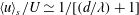 $\langle u\rangle _{s}/U\simeq 1/[(d/\unicode[STIX]{x1D706})+1]$
. For
$\langle u\rangle _{s}/U\simeq 1/[(d/\unicode[STIX]{x1D706})+1]$
. For
 $\unicode[STIX]{x1D719}_{s}\ll 1$
,
$\unicode[STIX]{x1D719}_{s}\ll 1$
,
 $\unicode[STIX]{x1D706}$
becomes much larger than
$\unicode[STIX]{x1D706}$
becomes much larger than
 $d$
and therefore
$d$
and therefore
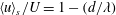 $\langle u\rangle _{s}/U=1-(d/\unicode[STIX]{x1D706})$
with a small
$\langle u\rangle _{s}/U=1-(d/\unicode[STIX]{x1D706})$
with a small
 $O(d/\unicode[STIX]{x1D706})$
error.
$O(d/\unicode[STIX]{x1D706})$
error.
3.2 Scaling of slip length for square array

Figure 6. (a) Normalised slip length versus area fraction and normalised gap size. The plots in panels (b) and (c) are projections of the surface plot of panel (a) onto the
 $\unicode[STIX]{x1D706}$
–
$\unicode[STIX]{x1D706}$
–
 $d$
and
$d$
and
 $\unicode[STIX]{x1D706}$
–
$\unicode[STIX]{x1D706}$
–
 $\unicode[STIX]{x1D719}_{s}$
planes, respectively. The inset in panel (c) shows the
$\unicode[STIX]{x1D719}_{s}$
planes, respectively. The inset in panel (c) shows the
 $\unicode[STIX]{x1D706}$
–
$\unicode[STIX]{x1D706}$
–
 $\unicode[STIX]{x1D719}_{s}$
relationship in log–log scale.
$\unicode[STIX]{x1D719}_{s}$
relationship in log–log scale.
Figure 6 shows the slip length
 $\unicode[STIX]{x1D706}$
as calculated from the definition (1.1). Consistently with the calculation of the slip velocity, the bulk shear rate at the interface
$\unicode[STIX]{x1D706}$
as calculated from the definition (1.1). Consistently with the calculation of the slip velocity, the bulk shear rate at the interface
 $\langle \dot{\unicode[STIX]{x1D6FE}}\rangle _{s}=\text{d}\langle u\rangle /\text{d}z$
is evaluated at
$\langle \dot{\unicode[STIX]{x1D6FE}}\rangle _{s}=\text{d}\langle u\rangle /\text{d}z$
is evaluated at
 $z=a$
. In the surface plot of figure 6(a),
$z=a$
. In the surface plot of figure 6(a),
 $\unicode[STIX]{x1D706}$
is plotted as a function of both
$\unicode[STIX]{x1D706}$
is plotted as a function of both
 $\unicode[STIX]{x1D719}_{s}$
and
$\unicode[STIX]{x1D719}_{s}$
and
 $d/a$
. Projections of figure 6 onto the
$d/a$
. Projections of figure 6 onto the
 $\unicode[STIX]{x1D706}$
–
$\unicode[STIX]{x1D706}$
–
 $d$
and
$d$
and
 $\unicode[STIX]{x1D706}$
–
$\unicode[STIX]{x1D706}$
–
 $\unicode[STIX]{x1D719}_{s}$
planes are shown in linear–linear plots in figure 6(b,c), respectively. The inset of figure 6(c) shows the
$\unicode[STIX]{x1D719}_{s}$
planes are shown in linear–linear plots in figure 6(b,c), respectively. The inset of figure 6(c) shows the
 $\unicode[STIX]{x1D706}$
–
$\unicode[STIX]{x1D706}$
–
 $\unicode[STIX]{x1D719}_{s}$
relation in log–log scale.
$\unicode[STIX]{x1D719}_{s}$
relation in log–log scale.
The slip length is seen to increase for increasing gap sizes, eventually saturating to an asymptotic value. A gap size
 $d=10a$
already gives a value of
$d=10a$
already gives a value of
 $\unicode[STIX]{x1D706}$
close to the asymptotic limit.
$\unicode[STIX]{x1D706}$
close to the asymptotic limit.
In figure 6(c), the values of
 $\unicode[STIX]{x1D706}$
for different values of
$\unicode[STIX]{x1D706}$
for different values of
 $d$
are seen to lie practically on the same curve, suggesting similar scaling laws for different gap sizes. The inset shows that the relation
$d$
are seen to lie practically on the same curve, suggesting similar scaling laws for different gap sizes. The inset shows that the relation
 $\unicode[STIX]{x1D706}$
–
$\unicode[STIX]{x1D706}$
–
 $\unicode[STIX]{x1D719}_{s}$
follows approximately a power law. To guess possible scaling exponents, we have examined the literature on flows over microstructured superhydrophobic surfaces. Ybert et al. (Reference Ybert, Barentin, Cottin-Bizonne, Joseph and Bocquet2007) developed a comprehensive theory for the dependence of the slip length on the area fraction for superhydrophobic surfaces. The theory was compared against literature data. Data for unconfined shear flow past a superhydrophobic surface composed of vertical pillars of circular or square cross-section could be fitted with good accuracy by a correlation of the form
$\unicode[STIX]{x1D719}_{s}$
follows approximately a power law. To guess possible scaling exponents, we have examined the literature on flows over microstructured superhydrophobic surfaces. Ybert et al. (Reference Ybert, Barentin, Cottin-Bizonne, Joseph and Bocquet2007) developed a comprehensive theory for the dependence of the slip length on the area fraction for superhydrophobic surfaces. The theory was compared against literature data. Data for unconfined shear flow past a superhydrophobic surface composed of vertical pillars of circular or square cross-section could be fitted with good accuracy by a correlation of the form
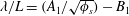 $\unicode[STIX]{x1D706}/L=(A_{1}/\sqrt{\unicode[STIX]{x1D719}_{s}})-B_{1}$
, where
$\unicode[STIX]{x1D706}/L=(A_{1}/\sqrt{\unicode[STIX]{x1D719}_{s}})-B_{1}$
, where
 $L$
is the distance between the pillars, and
$L$
is the distance between the pillars, and
 $A_{1}$
and
$A_{1}$
and
 $B_{1}$
are constants. Ybert et al. (Reference Ybert, Barentin, Cottin-Bizonne, Joseph and Bocquet2007) proposed
$B_{1}$
are constants. Ybert et al. (Reference Ybert, Barentin, Cottin-Bizonne, Joseph and Bocquet2007) proposed
 $A_{1}=0.325$
and
$A_{1}=0.325$
and
 $B_{1}=0.44$
(the analytical expressions proposed by Davis & Lauga (Reference Davis and Lauga2010) give coefficient values very close to those indicated by Ybert et al. (Reference Ybert, Barentin, Cottin-Bizonne, Joseph and Bocquet2007)). In the dilute limit, i.e. in our case for
$B_{1}=0.44$
(the analytical expressions proposed by Davis & Lauga (Reference Davis and Lauga2010) give coefficient values very close to those indicated by Ybert et al. (Reference Ybert, Barentin, Cottin-Bizonne, Joseph and Bocquet2007)). In the dilute limit, i.e. in our case for
 $\unicode[STIX]{x1D719}_{s}\ll (A_{1}/B_{1})^{2}\simeq 0.54$
, the correlation above reduces to
$\unicode[STIX]{x1D719}_{s}\ll (A_{1}/B_{1})^{2}\simeq 0.54$
, the correlation above reduces to
 $\unicode[STIX]{x1D706}/L\sim 1/\sqrt{\unicode[STIX]{x1D719}_{s}}$
, which is equivalent to
$\unicode[STIX]{x1D706}/L\sim 1/\sqrt{\unicode[STIX]{x1D719}_{s}}$
, which is equivalent to
 $\unicode[STIX]{x1D706}/a\sim 1/\unicode[STIX]{x1D719}_{s}$
. This scaling can be understood from the fact that in the dilute limit the ratio of the hydrodynamic force on each pillar to the slip velocity is expected to be practically independent of
$\unicode[STIX]{x1D706}/a\sim 1/\unicode[STIX]{x1D719}_{s}$
. This scaling can be understood from the fact that in the dilute limit the ratio of the hydrodynamic force on each pillar to the slip velocity is expected to be practically independent of
 $\unicode[STIX]{x1D719}_{s}$
. The tangential stress on the monolayer due to the bulk flow is proportional to the ratio of the hydrodynamic force and
$\unicode[STIX]{x1D719}_{s}$
. The tangential stress on the monolayer due to the bulk flow is proportional to the ratio of the hydrodynamic force and
 $L^{2}$
. Since the tangential stress for a Newtonian fluid is proportional to the macroscopic shear rate, then (1.1) yields
$L^{2}$
. Since the tangential stress for a Newtonian fluid is proportional to the macroscopic shear rate, then (1.1) yields
 $\unicode[STIX]{x1D706}\propto a/\unicode[STIX]{x1D719}_{s}$
for
$\unicode[STIX]{x1D706}\propto a/\unicode[STIX]{x1D719}_{s}$
for
 $\unicode[STIX]{x1D719}_{s}\ll 1$
.
$\unicode[STIX]{x1D719}_{s}\ll 1$
.

Figure 7. (a) Normalised slip length versus
 $\unicode[STIX]{x1D719}_{s}^{-1}$
. The continuous line is (3.2), developed by Ybert et al. (Reference Ybert, Barentin, Cottin-Bizonne, Joseph and Bocquet2007) for flow past a superhydrophobic surface. The dashed line is (3.3), where (3.2) has been rescaled by the ratio of the Stokes drag coefficient for a sphere to that for a thin disk. (b) Normalised slip length versus
$\unicode[STIX]{x1D719}_{s}^{-1}$
. The continuous line is (3.2), developed by Ybert et al. (Reference Ybert, Barentin, Cottin-Bizonne, Joseph and Bocquet2007) for flow past a superhydrophobic surface. The dashed line is (3.3), where (3.2) has been rescaled by the ratio of the Stokes drag coefficient for a sphere to that for a thin disk. (b) Normalised slip length versus
 $(1-\unicode[STIX]{x1D719}_{s})^{2}/\sqrt{\unicode[STIX]{x1D719}_{s}}$
showing the dense limit
$(1-\unicode[STIX]{x1D719}_{s})^{2}/\sqrt{\unicode[STIX]{x1D719}_{s}}$
showing the dense limit
 $\unicode[STIX]{x1D719}_{s}=35\,\%{-}70\,\%$
for
$\unicode[STIX]{x1D719}_{s}=35\,\%{-}70\,\%$
for
 $d=4a$
.
$d=4a$
.
The argument above is expected to hold independently of the specific geometry of the solid object in contact with the fluid interface. Therefore, it should be possible to apply the scaling proposed by Ybert et al. (Reference Ybert, Barentin, Cottin-Bizonne, Joseph and Bocquet2007) to our case. This expectation is confirmed in figure 7(a), where
 $\unicode[STIX]{x1D706}/a$
is plotted as a function of
$\unicode[STIX]{x1D706}/a$
is plotted as a function of
 $1/\unicode[STIX]{x1D719}_{s}$
for values of
$1/\unicode[STIX]{x1D719}_{s}$
for values of
 $\unicode[STIX]{x1D719}_{s}$
corresponding to a relatively dilute monolayer. A linear correlation fits the data remarkably well. From figure 7(a) it appears that a linear scaling holds for any value of
$\unicode[STIX]{x1D719}_{s}$
corresponding to a relatively dilute monolayer. A linear correlation fits the data remarkably well. From figure 7(a) it appears that a linear scaling holds for any value of
 $d$
. The log–log plot in the inset of figure 6(b) shows that the power-law exponent has a small dependence on
$d$
. The log–log plot in the inset of figure 6(b) shows that the power-law exponent has a small dependence on
 $d$
for
$d$
for
 $d\leqslant 4a$
. However, differences between the exponents corresponding to different values of
$d\leqslant 4a$
. However, differences between the exponents corresponding to different values of
 $d$
are approximately
$d$
are approximately
 $10\,\%$
of the
$10\,\%$
of the
 $d=20a$
case, and therefore not noticeable if the data are plotted as in figure 7(a).
$d=20a$
case, and therefore not noticeable if the data are plotted as in figure 7(a).
While the functional form proposed by Ybert et al. (Reference Ybert, Barentin, Cottin-Bizonne, Joseph and Bocquet2007) does fit our data well, the prefactors are different. The function
 $\unicode[STIX]{x1D706}/a=(A_{1}\sqrt{\unicode[STIX]{x03C0}}/\unicode[STIX]{x1D719}_{s})-(B_{1}\sqrt{\unicode[STIX]{x03C0}}/\unicode[STIX]{x1D719}_{s}^{1/2})$
, obtained using the definition
$\unicode[STIX]{x1D706}/a=(A_{1}\sqrt{\unicode[STIX]{x03C0}}/\unicode[STIX]{x1D719}_{s})-(B_{1}\sqrt{\unicode[STIX]{x03C0}}/\unicode[STIX]{x1D719}_{s}^{1/2})$
, obtained using the definition
 $\unicode[STIX]{x1D719}_{s}=\unicode[STIX]{x03C0}a^{2}/L^{2}$
, is plotted as a continuous line in figure 7(a), using the coefficient values for
$\unicode[STIX]{x1D719}_{s}=\unicode[STIX]{x03C0}a^{2}/L^{2}$
, is plotted as a continuous line in figure 7(a), using the coefficient values for
 $A_{1}$
and
$A_{1}$
and
 $B_{1}$
suggested by Ybert et al. This function is seen to overpredict the magnitude of the slip length computed in our simulation.
$B_{1}$
suggested by Ybert et al. This function is seen to overpredict the magnitude of the slip length computed in our simulation.
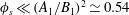
There is a simple explanation for the difference between our result and that of Ybert et al. (Reference Ybert, Barentin, Cottin-Bizonne, Joseph and Bocquet2007). The flow configuration considered by those authors can be interpreted as shear flow past a monolayer of infinitely thin disks (representing the top surfaces of the pillars composing the superhydrophobic surface). In our case the spheres protrude significantly into the liquid. Several studies in the context of superhydrophobic surfaces have shown that a larger protrusion produces smaller slip lengths (Sbragaglia & Prosperetti Reference Sbragaglia and Prosperetti2007; Ng & Wang Reference Ng and Wang2009; Kumar, Datta & Kalyanasundaram Reference Kumar, Datta and Kalyanasundaram2016; Shelley et al. Reference Shelley, Smith, Hibbins, Sambles and Horsley2016). Therefore, a smaller slip length in the current case of a sphere monolayer is not unexpected.
We can attempt a simple correction to (3.2) to account for the finite protrusion of the spheres into the flow. For a given free-stream velocity, the hydrodynamic drag on an infinitely thin disk in a uniform flow is
 $9\unicode[STIX]{x03C0}/16$
times smaller than the drag on a sphere having the same radius. Assuming that tangential stress due to the bulk flow is approximately proportional to the slip velocity (we will confirm this hypothesis in § 3.3), it should be expected that, for sufficiently dilute systems, the slip length for flow past a monolayer of spheres embedded in a gas–liquid interface is a factor of
$9\unicode[STIX]{x03C0}/16$
times smaller than the drag on a sphere having the same radius. Assuming that tangential stress due to the bulk flow is approximately proportional to the slip velocity (we will confirm this hypothesis in § 3.3), it should be expected that, for sufficiently dilute systems, the slip length for flow past a monolayer of spheres embedded in a gas–liquid interface is a factor of
 $9\unicode[STIX]{x03C0}/16$
smaller than that predicted by (3.2). To verify this approximation, we plot the function
$9\unicode[STIX]{x03C0}/16$
smaller than that predicted by (3.2). To verify this approximation, we plot the function
 $$\begin{eqnarray}\frac{\unicode[STIX]{x1D706}}{a}=\frac{A_{2}}{\unicode[STIX]{x1D719}_{s}}-\frac{B_{2}}{\unicode[STIX]{x1D719}_{s}^{1/2}}\end{eqnarray}$$
as a thick dashed line in figure 7(a). Here
 $A_{2}=(16\unicode[STIX]{x03C0}\sqrt{\unicode[STIX]{x03C0}}/9)A_{1}$
and
$A_{2}=(16\unicode[STIX]{x03C0}\sqrt{\unicode[STIX]{x03C0}}/9)A_{1}$
and
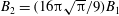 $B_{2}=(16\unicode[STIX]{x03C0}\sqrt{\unicode[STIX]{x03C0}}/9)B_{1}$
. The values given by this corrected expression are remarkably close to our data, suggesting that the difference between the data of Ybert et al. (Reference Ybert, Barentin, Cottin-Bizonne, Joseph and Bocquet2007) and ours can be mainly attributed to the larger drag produced by the protruding spheres on the flowing liquid as opposed to the flat top surfaces of the pillars.
$B_{2}=(16\unicode[STIX]{x03C0}\sqrt{\unicode[STIX]{x03C0}}/9)B_{1}$
. The values given by this corrected expression are remarkably close to our data, suggesting that the difference between the data of Ybert et al. (Reference Ybert, Barentin, Cottin-Bizonne, Joseph and Bocquet2007) and ours can be mainly attributed to the larger drag produced by the protruding spheres on the flowing liquid as opposed to the flat top surfaces of the pillars.

Figure 8. Tangential stress due to the bulk flow normalised by (a) the wall velocity
 $U$
or (b) the slip velocity
$U$
or (b) the slip velocity
 $\langle u\rangle _{s}$
as a function of the solid area fraction. The inset in panel (b) shows a zoom for small values of
$\langle u\rangle _{s}$
as a function of the solid area fraction. The inset in panel (b) shows a zoom for small values of
 $\unicode[STIX]{x1D719}_{s}$
of the effective friction coefficient
$\unicode[STIX]{x1D719}_{s}$
of the effective friction coefficient
 $\unicode[STIX]{x1D70F}a/(\unicode[STIX]{x1D707}\langle u\rangle _{s}\unicode[STIX]{x1D719}_{s})$
.
$\unicode[STIX]{x1D70F}a/(\unicode[STIX]{x1D707}\langle u\rangle _{s}\unicode[STIX]{x1D719}_{s})$
.
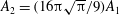
The scaling law discussed above holds for a relatively dilute limit (the data points clearly discernible in figure 7(a) correspond to
 $\unicode[STIX]{x1D719}_{s}\leqslant 4\,\%$
, while these corresponding to the dense limits are clustered near the origin and are barely visible). In the dense limit, the slip velocity results from a fraction
$\unicode[STIX]{x1D719}_{s}\leqslant 4\,\%$
, while these corresponding to the dense limits are clustered near the origin and are barely visible). In the dense limit, the slip velocity results from a fraction
 $1-\unicode[STIX]{x1D719}_{s}$
of the plane
$1-\unicode[STIX]{x1D719}_{s}$
of the plane
 $z=a$
occupied by the gas–liquid interfaces. Since the slip velocity in these regions is of the order of
$z=a$
occupied by the gas–liquid interfaces. Since the slip velocity in these regions is of the order of
 $\langle \dot{\unicode[STIX]{x1D6FE}}\rangle _{s}L(1-\unicode[STIX]{x1D719}_{s})$
(Ybert et al.
Reference Ybert, Barentin, Cottin-Bizonne, Joseph and Bocquet2007) and
$\langle \dot{\unicode[STIX]{x1D6FE}}\rangle _{s}L(1-\unicode[STIX]{x1D719}_{s})$
(Ybert et al.
Reference Ybert, Barentin, Cottin-Bizonne, Joseph and Bocquet2007) and
 $L\propto \unicode[STIX]{x1D719}_{s}^{-1/2}$
, we expect
$L\propto \unicode[STIX]{x1D719}_{s}^{-1/2}$
, we expect
 $\unicode[STIX]{x1D706}\sim a(1-\unicode[STIX]{x1D719}_{s})^{2}/\sqrt{\unicode[STIX]{x1D719}_{s}}$
. Figure 7(b) shows that the simulation data follow this scaling law with very good accuracy.
$\unicode[STIX]{x1D706}\sim a(1-\unicode[STIX]{x1D719}_{s})^{2}/\sqrt{\unicode[STIX]{x1D719}_{s}}$
. Figure 7(b) shows that the simulation data follow this scaling law with very good accuracy.
3.3 Tangential stress due to the bulk flow: square array
In many situations of practical interest it would be useful to estimate the drag per unit area on the particles due to the motion of the bulk fluid (or ‘subphase’, as it is often called in the surfactants literature). We call the hydrodynamic drag on the particles per unit area the tangential stress due to the bulk flow, and denote this quantity by
 $\unicode[STIX]{x1D70F}$
. In the current paper,
$\unicode[STIX]{x1D70F}$
. In the current paper,
 $\unicode[STIX]{x1D70F}$
for a square array is calculated as
$\unicode[STIX]{x1D70F}$
for a square array is calculated as
 $\unicode[STIX]{x1D70F}=F_{x}/L^{2}$
, where
$\unicode[STIX]{x1D70F}=F_{x}/L^{2}$
, where
 $F_{x}$
is the
$F_{x}$
is the
 $x$
component of the hydrodynamic force acting on each sphere in the monolayer.
$x$
component of the hydrodynamic force acting on each sphere in the monolayer.
In figure 8(a),
 $\unicode[STIX]{x1D70F}$
is normalised by using
$\unicode[STIX]{x1D70F}$
is normalised by using
 $U$
as velocity scale. With this normalisation, the normalised value of
$U$
as velocity scale. With this normalisation, the normalised value of
 $\unicode[STIX]{x1D70F}$
has a relatively strong dependence on both
$\unicode[STIX]{x1D70F}$
has a relatively strong dependence on both
 $\unicode[STIX]{x1D719}_{s}$
and
$\unicode[STIX]{x1D719}_{s}$
and
 $d$
. However, we note that the wall velocity is characteristic of the fluid velocity ‘seen’ by the particles only in the extremely dilute limit for which the velocity profile is almost a plug flow. An improved parametrisation of the shear stress and pressure exerted on each particle by the bulk flow is expected to be given by the slip velocity
$d$
. However, we note that the wall velocity is characteristic of the fluid velocity ‘seen’ by the particles only in the extremely dilute limit for which the velocity profile is almost a plug flow. An improved parametrisation of the shear stress and pressure exerted on each particle by the bulk flow is expected to be given by the slip velocity
 $\langle u\rangle _{s}$
. In figure 8(b),
$\langle u\rangle _{s}$
. In figure 8(b),
 $\unicode[STIX]{x1D70F}$
is normalised by
$\unicode[STIX]{x1D70F}$
is normalised by
 $\langle u\rangle _{s}$
. Using the slip velocity in the normalisation causes the data to collapse onto a single curve for any value of
$\langle u\rangle _{s}$
. Using the slip velocity in the normalisation causes the data to collapse onto a single curve for any value of
 $d$
.
$d$
.
The fact that
 $\unicode[STIX]{x1D70F}$
is practically proportional to the slip velocity suggests the introduction of a non-dimensional friction coefficient
$\unicode[STIX]{x1D70F}$
is practically proportional to the slip velocity suggests the introduction of a non-dimensional friction coefficient
 $\unicode[STIX]{x1D70F}a/(\unicode[STIX]{x1D707}\langle u\rangle _{s}\unicode[STIX]{x1D719}_{s})$
having only a marginal dependence on
$\unicode[STIX]{x1D70F}a/(\unicode[STIX]{x1D707}\langle u\rangle _{s}\unicode[STIX]{x1D719}_{s})$
having only a marginal dependence on
 $d$
and
$d$
and
 $\unicode[STIX]{x1D719}_{s}$
. A linear fit to the data in figure 8(b) suggests a non-dimensional friction coefficient of approximately
$\unicode[STIX]{x1D719}_{s}$
. A linear fit to the data in figure 8(b) suggests a non-dimensional friction coefficient of approximately
 $7$
. For small values of
$7$
. For small values of
 $\unicode[STIX]{x1D719}_{s}$
the friction coefficient is smaller than 7 and non-constant (see inset), suggesting that the relation between
$\unicode[STIX]{x1D719}_{s}$
the friction coefficient is smaller than 7 and non-constant (see inset), suggesting that the relation between
 $\unicode[STIX]{x1D70F}/\langle u\rangle _{s}$
and
$\unicode[STIX]{x1D70F}/\langle u\rangle _{s}$
and
 $\unicode[STIX]{x1D719}_{s}$
is linear only in an approximate sense.
$\unicode[STIX]{x1D719}_{s}$
is linear only in an approximate sense.
In the limit
 $\unicode[STIX]{x1D719}_{s}\rightarrow 0$
and
$\unicode[STIX]{x1D719}_{s}\rightarrow 0$
and
 $d\rightarrow \infty$
, we expect
$d\rightarrow \infty$
, we expect
 $F_{x}\simeq 3\unicode[STIX]{x03C0}\unicode[STIX]{x1D707}aU$
(i.e. half the Stokes drag on a fully immersed sphere). Since
$F_{x}\simeq 3\unicode[STIX]{x03C0}\unicode[STIX]{x1D707}aU$
(i.e. half the Stokes drag on a fully immersed sphere). Since
 $\langle u\rangle _{s}$
tends to
$\langle u\rangle _{s}$
tends to
 $U$
as
$U$
as
 $\unicode[STIX]{x1D719}_{s}\rightarrow 0$
(figure 5
a), and by definition
$\unicode[STIX]{x1D719}_{s}\rightarrow 0$
(figure 5
a), and by definition
 $\unicode[STIX]{x1D70F}=F/L^{2}=F\unicode[STIX]{x1D719}_{s}/(\unicode[STIX]{x03C0}a^{2})$
for a square array, one might expect a friction coefficient of approximately
$\unicode[STIX]{x1D70F}=F/L^{2}=F\unicode[STIX]{x1D719}_{s}/(\unicode[STIX]{x03C0}a^{2})$
for a square array, one might expect a friction coefficient of approximately
 $3$
in the limits
$3$
in the limits
 $\unicode[STIX]{x1D719}_{s}\rightarrow 0$
and
$\unicode[STIX]{x1D719}_{s}\rightarrow 0$
and
 $d\rightarrow \infty$
. For small values of
$d\rightarrow \infty$
. For small values of
 $\unicode[STIX]{x1D719}_{s}$
the data do appear to converge to a friction coefficient of 3 as
$\unicode[STIX]{x1D719}_{s}$
the data do appear to converge to a friction coefficient of 3 as
 $d$
increases (see inset of figure 8
b). However, the convergence is slow and for the values that we simulated the friction coefficient is significantly larger than 3 even for the smallest values of
$d$
increases (see inset of figure 8
b). However, the convergence is slow and for the values that we simulated the friction coefficient is significantly larger than 3 even for the smallest values of
 $\unicode[STIX]{x1D719}_{s}$
we considered. This fact may be due to the strong dependence of
$\unicode[STIX]{x1D719}_{s}$
we considered. This fact may be due to the strong dependence of
 $\langle u\rangle _{s}$
on the surface fraction (figure 5
a). One would need to simulate truly negligible values of
$\langle u\rangle _{s}$
on the surface fraction (figure 5
a). One would need to simulate truly negligible values of
 $\unicode[STIX]{x1D719}_{s}$
, and therefore use extremely large computational domains, to recover the expected asymptotic limit.
$\unicode[STIX]{x1D719}_{s}$
, and therefore use extremely large computational domains, to recover the expected asymptotic limit.

Figure 9. Normalised pressure (a) and viscous (b) contributions to
 $\unicode[STIX]{x1D70F}$
.
$\unicode[STIX]{x1D70F}$
.
The expansion in spherical harmonics in Physalis enables one to easily compute the pressure and viscous components of the hydrodynamic force on each sphere with excellent accuracy (Zhang & Prosperetti Reference Zhang and Prosperetti2005; Bluemink et al.
Reference Bluemink, Lohse, Prosperetti and Van Wijngaarden2010; Botto & Prosperetti Reference Botto and Prosperetti2012). Upon normalisation, these force components yield
 $\unicode[STIX]{x1D70F}_{p}$
and
$\unicode[STIX]{x1D70F}_{p}$
and
 $\unicode[STIX]{x1D70F}_{v}$
, namely the pressure and viscous contributions to
$\unicode[STIX]{x1D70F}_{v}$
, namely the pressure and viscous contributions to
 $\unicode[STIX]{x1D70F}$
, respectively. Figure 9(a,b) shows
$\unicode[STIX]{x1D70F}$
, respectively. Figure 9(a,b) shows
 $\unicode[STIX]{x1D70F}_{p}$
and
$\unicode[STIX]{x1D70F}_{p}$
and
 $\unicode[STIX]{x1D70F}_{v}$
as a function of
$\unicode[STIX]{x1D70F}_{v}$
as a function of
 $\unicode[STIX]{x1D719}_{s}$
for different values of
$\unicode[STIX]{x1D719}_{s}$
for different values of
 $d$
. As expected from the analytical solution for Stokes flow past a sphere, which suggests that pressure and viscous contributions to the drag are comparable, for
$d$
. As expected from the analytical solution for Stokes flow past a sphere, which suggests that pressure and viscous contributions to the drag are comparable, for
 $\unicode[STIX]{x1D719}_{s}\ll 1$
the viscous and pressure contributions to
$\unicode[STIX]{x1D719}_{s}\ll 1$
the viscous and pressure contributions to
 $\unicode[STIX]{x1D70F}$
are comparable in magnitude. For intermediate and relatively large values of
$\unicode[STIX]{x1D70F}$
are comparable in magnitude. For intermediate and relatively large values of
 $\unicode[STIX]{x1D719}_{s}$
, viscous stresses produce the dominant contribution to
$\unicode[STIX]{x1D719}_{s}$
, viscous stresses produce the dominant contribution to
 $\unicode[STIX]{x1D70F}$
. For instance, for
$\unicode[STIX]{x1D70F}$
. For instance, for
 $d=7a$
and
$d=7a$
and
 $\unicode[STIX]{x1D719}_{s}>0.5$
,
$\unicode[STIX]{x1D719}_{s}>0.5$
,
 $\unicode[STIX]{x1D70F}_{v}$
is approximately one order of magnitude larger than
$\unicode[STIX]{x1D70F}_{v}$
is approximately one order of magnitude larger than
 $\unicode[STIX]{x1D70F}_{p}$
. The contribution
$\unicode[STIX]{x1D70F}_{p}$
. The contribution
 $\unicode[STIX]{x1D70F}_{p}$
is only significant for small gap sizes, particularly at the highest values of the area fraction. This result confirms the intuitive notion that the largest contribution to
$\unicode[STIX]{x1D70F}_{p}$
is only significant for small gap sizes, particularly at the highest values of the area fraction. This result confirms the intuitive notion that the largest contribution to
 $\unicode[STIX]{x1D70F}$
for a moderately dense monolayer originates from the shear forces exerted by the fluid on the portion of the sphere surfaces where the streamwise fluid velocity is larger.
$\unicode[STIX]{x1D70F}$
for a moderately dense monolayer originates from the shear forces exerted by the fluid on the portion of the sphere surfaces where the streamwise fluid velocity is larger.
For completeness, we also report in figure 10 the hydrodynamic force on each particle in the square monolayer as a function of
 $d$
for different values of
$d$
for different values of
 $\unicode[STIX]{x1D719}_{s}$
. In contrast to the previous figures in which the tangential stress due to the bulk flow was reported, in figure 10 the force is not normalised by
$\unicode[STIX]{x1D719}_{s}$
. In contrast to the previous figures in which the tangential stress due to the bulk flow was reported, in figure 10 the force is not normalised by
 $L^{2}$
, and therefore the dependence on
$L^{2}$
, and therefore the dependence on
 $\unicode[STIX]{x1D719}_{s}$
is perhaps more clear. This graph could be useful to quantify how the drag on a surface-active particle embedded at the boundary of a thin film between a particle-laden interface and a wall changes as a function of the thickness of the film.
$\unicode[STIX]{x1D719}_{s}$
is perhaps more clear. This graph could be useful to quantify how the drag on a surface-active particle embedded at the boundary of a thin film between a particle-laden interface and a wall changes as a function of the thickness of the film.

Figure 10. Hydrodynamic force on each sphere in the square array as a function of the gap size.
3.4 Reticulated array
The slip length depends on the specific microstructure of the monolayer. Two categories of microstructures are particularly relevant to particle-laden interfaces: well-dispersed systems, in which the particles are not in contact when
 $\unicode[STIX]{x1D719}_{s}$
is smaller than the maximum packing fraction; and percolating networks, where the particles form connected chains that span the boundaries of the interface (see e.g. Aveyard et al.
Reference Aveyard, Clint, Nees and Paunov2000). The square array case examined in the previous section belongs to the first category. The percolating network case is examined in the current section. To get initial insights into more realistic situations, in which the percolating networks are disordered and are characterised by a variety of scales, in this section we simulate a periodic mesh-like reticulated arrangement. One example of such an arrangement is illustrated in figure 11(b).
$\unicode[STIX]{x1D719}_{s}$
is smaller than the maximum packing fraction; and percolating networks, where the particles form connected chains that span the boundaries of the interface (see e.g. Aveyard et al.
Reference Aveyard, Clint, Nees and Paunov2000). The square array case examined in the previous section belongs to the first category. The percolating network case is examined in the current section. To get initial insights into more realistic situations, in which the percolating networks are disordered and are characterised by a variety of scales, in this section we simulate a periodic mesh-like reticulated arrangement. One example of such an arrangement is illustrated in figure 11(b).

Figure 11. Schematic of a square array (a) and a reticulated array (b) for the same value of the solid area fraction,
 $\unicode[STIX]{x1D719}_{s}=43.63\,\%$
.
$\unicode[STIX]{x1D719}_{s}=43.63\,\%$
.
Table 1. Normalised slip length,
 $\unicode[STIX]{x1D706}/a$
, and normalised tangential stress due to the bulk flow,
$\unicode[STIX]{x1D706}/a$
, and normalised tangential stress due to the bulk flow,
 $\unicode[STIX]{x1D70F}a/\unicode[STIX]{x1D707}U$
, for reticulated arrays characterised by different values of the area fraction
$\unicode[STIX]{x1D70F}a/\unicode[STIX]{x1D707}U$
, for reticulated arrays characterised by different values of the area fraction
 $\unicode[STIX]{x1D719}_{s}$
and mesh size
$\unicode[STIX]{x1D719}_{s}$
and mesh size
 $L$
, for
$L$
, for
 $d/a=7$
. The last two columns report the values of
$d/a=7$
. The last two columns report the values of
 $\unicode[STIX]{x1D706}$
and
$\unicode[STIX]{x1D706}$
and
 $\unicode[STIX]{x1D70F}$
for a square array having the same solid area fraction as the corresponding reticulated array.
$\unicode[STIX]{x1D70F}$
for a square array having the same solid area fraction as the corresponding reticulated array.

The simulations for the reticulated array case are carried out by including in the doubly periodic simulation box a variable number of spheres. The spheres form two orthogonal rectilinear chains that intersect each other in the centre of the domain. One of the chains is oriented along the flow direction.
Because of the need to consider several particles, simulating reticulated arrays requires a significantly larger domain than for a square array, for a given area fraction. To limit the number of simulations while allowing the exploration of the relevant parameter space, the majority of the simulations presented in this section are carried out for a fixed gap size,
 $d=7a$
. Preliminary tests confirm that this gap size is sufficiently large for the results to reasonably approximate the unbounded case
$d=7a$
. Preliminary tests confirm that this gap size is sufficiently large for the results to reasonably approximate the unbounded case
 $d=\infty$
.
$d=\infty$
.
Table 1 summarises values of the slip length
 $\unicode[STIX]{x1D706}$
and tangential stress
$\unicode[STIX]{x1D706}$
and tangential stress
 $\unicode[STIX]{x1D70F}$
due to the bulk flow for different values of
$\unicode[STIX]{x1D70F}$
due to the bulk flow for different values of
 $L$
(and therefore of
$L$
(and therefore of
 $\unicode[STIX]{x1D719}_{s}$
). The last two columns in table 1 report the values of
$\unicode[STIX]{x1D719}_{s}$
). The last two columns in table 1 report the values of
 $\unicode[STIX]{x1D706}$
and
$\unicode[STIX]{x1D706}$
and
 $\unicode[STIX]{x1D70F}$
for a square array having the same area fraction as the corresponding reticulated array. These two quantities are denoted by the symbols
$\unicode[STIX]{x1D70F}$
for a square array having the same area fraction as the corresponding reticulated array. These two quantities are denoted by the symbols
 $\unicode[STIX]{x1D706}_{sq}$
and
$\unicode[STIX]{x1D706}_{sq}$
and
 $\unicode[STIX]{x1D70F}_{sq}$
, respectively.
$\unicode[STIX]{x1D70F}_{sq}$
, respectively.
Comparison of
 $\unicode[STIX]{x1D706}$
with
$\unicode[STIX]{x1D706}$
with
 $\unicode[STIX]{x1D706}_{sq}$
shows that, for a given surface coverage and particle size, the reticulated array gives a significantly larger value of the slip length. The effect of the specific microstructure (square array versus reticulated array) on
$\unicode[STIX]{x1D706}_{sq}$
shows that, for a given surface coverage and particle size, the reticulated array gives a significantly larger value of the slip length. The effect of the specific microstructure (square array versus reticulated array) on
 $\unicode[STIX]{x1D706}$
becomes more and more significant as
$\unicode[STIX]{x1D706}$
becomes more and more significant as
 $\unicode[STIX]{x1D719}_{s}$
decreases. The difference between
$\unicode[STIX]{x1D719}_{s}$
decreases. The difference between
 $\unicode[STIX]{x1D70F}$
and
$\unicode[STIX]{x1D70F}$
and
 $\unicode[STIX]{x1D70F}_{sq}$
is comparatively small.
$\unicode[STIX]{x1D70F}_{sq}$
is comparatively small.

Figure 12. (a) Normalised slip velocity and (b) normalised bulk shear rate at the interface as a function of solid area fraction for
 $d/a=7$
, comparing square and reticulated arrays.
$d/a=7$
, comparing square and reticulated arrays.
Why does the reticulated array give a larger slip length? The slip length is defined as the ratio of
 $\langle u\rangle _{s}$
to
$\langle u\rangle _{s}$
to
 $\langle \dot{\unicode[STIX]{x1D6FE}}\rangle _{s}$
. A difference in slip length can therefore be attributed to: (i) differences in
$\langle \dot{\unicode[STIX]{x1D6FE}}\rangle _{s}$
. A difference in slip length can therefore be attributed to: (i) differences in
 $\langle u\rangle _{s}$
; (ii) differences in
$\langle u\rangle _{s}$
; (ii) differences in
 $\langle \dot{\unicode[STIX]{x1D6FE}}\rangle _{s}$
; or (iii) the combined effect of both quantities. Figure 12(a) compares values of
$\langle \dot{\unicode[STIX]{x1D6FE}}\rangle _{s}$
; or (iii) the combined effect of both quantities. Figure 12(a) compares values of
 $\langle u\rangle _{s}$
obtained with the reticulated array to those obtained with the square array. The corresponding values of
$\langle u\rangle _{s}$
obtained with the reticulated array to those obtained with the square array. The corresponding values of
 $\langle \dot{\unicode[STIX]{x1D6FE}}\rangle _{s}$
are shown in figure 12(b).
$\langle \dot{\unicode[STIX]{x1D6FE}}\rangle _{s}$
are shown in figure 12(b).
It can be seen that the values of
 $\langle u\rangle _{s}$
given by the two microstructures are comparable only for relatively large values of
$\langle u\rangle _{s}$
given by the two microstructures are comparable only for relatively large values of
 $\unicode[STIX]{x1D719}_{s}$
. For moderate and small values of
$\unicode[STIX]{x1D719}_{s}$
. For moderate and small values of
 $\unicode[STIX]{x1D719}_{s}$
, the reticulated array gives a significantly larger value of
$\unicode[STIX]{x1D719}_{s}$
, the reticulated array gives a significantly larger value of
 $\langle u\rangle _{s}$
than the square array. Over a similar range of values of
$\langle u\rangle _{s}$
than the square array. Over a similar range of values of
 $\unicode[STIX]{x1D719}_{s}$
, the differences in the values of
$\unicode[STIX]{x1D719}_{s}$
, the differences in the values of
 $\langle \dot{\unicode[STIX]{x1D6FE}}\rangle _{s}$
corresponding to the two microstructures are relatively small (figure 12
b). The observed dependence of the slip length on the microstructure is thus mainly due to changes in the slip velocity, while changes in the bulk shear rate at the interface play a relatively marginal role.
$\langle \dot{\unicode[STIX]{x1D6FE}}\rangle _{s}$
corresponding to the two microstructures are relatively small (figure 12
b). The observed dependence of the slip length on the microstructure is thus mainly due to changes in the slip velocity, while changes in the bulk shear rate at the interface play a relatively marginal role.

Figure 13. Contours of normalised streamwise velocity,
 $u/U$
, in the plane
$u/U$
, in the plane
 $z=a$
for (a) square array and (b) reticulated array. The solid area fraction in (a) and (b) is
$z=a$
for (a) square array and (b) reticulated array. The solid area fraction in (a) and (b) is
 $\unicode[STIX]{x1D719}_{s}=43.63\,\%$
and
$\unicode[STIX]{x1D719}_{s}=43.63\,\%$
and
 $d/a=7$
.
$d/a=7$
.
A question arises as to why the slip velocity is larger in the case of the reticulated array. Comparison of figure 11(a) with figure 11(b) shows that, for a given area fraction, the reticulated array is characterised by larger connected regions not occupied by particles. Because the flow in these regions is relatively unobstructed by the particles, the slip velocity in these regions could be substantially larger than the slip velocity in the interstices between the particles in the square array case. To verify this hypothesis, we plotted isocontours of
 $u$
in the plane
$u$
in the plane
 $z=a$
, comparing the reticulated and square arrays (figure 13). The characteristic velocities in the open areas bounded by chains in the reticulated array case are at least
$z=a$
, comparing the reticulated and square arrays (figure 13). The characteristic velocities in the open areas bounded by chains in the reticulated array case are at least
 $50\,\%$
larger than those in the interstices between particles in the square array case. These relatively large velocities are spread over regions of linear size comparable to the mesh size
$50\,\%$
larger than those in the interstices between particles in the square array case. These relatively large velocities are spread over regions of linear size comparable to the mesh size
 $L$
. In contrast, in the square array the smaller slip velocities are spread over regions of characteristic linear dimension
$L$
. In contrast, in the square array the smaller slip velocities are spread over regions of characteristic linear dimension
 $\ell \ll L$
, where
$\ell \ll L$
, where
 $\ell$
is the average inter-particle separation. We have
$\ell$
is the average inter-particle separation. We have
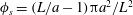 $\unicode[STIX]{x1D719}_{s}=(L/a-1)\unicode[STIX]{x03C0}a^{2}/L^{2}$
for the reticulated array and
$\unicode[STIX]{x1D719}_{s}=(L/a-1)\unicode[STIX]{x03C0}a^{2}/L^{2}$
for the reticulated array and
 $\unicode[STIX]{x1D719}_{s}=\unicode[STIX]{x03C0}a^{2}/\ell ^{2}$
for the square array. Therefore, the ratio
$\unicode[STIX]{x1D719}_{s}=\unicode[STIX]{x03C0}a^{2}/\ell ^{2}$
for the square array. Therefore, the ratio
 $L^{2}/\ell ^{2}$
of the interfacial areas occupied by high-velocity fluid (reticulated array) to that occupied by low-velocity fluid increases with decreasing
$L^{2}/\ell ^{2}$
of the interfacial areas occupied by high-velocity fluid (reticulated array) to that occupied by low-velocity fluid increases with decreasing
 $\unicode[STIX]{x1D719}_{s}$
. Since the slip velocity is an area-averaged quantity, larger local velocities spread over larger areas will give a larger value of the slip velocity.
$\unicode[STIX]{x1D719}_{s}$
. Since the slip velocity is an area-averaged quantity, larger local velocities spread over larger areas will give a larger value of the slip velocity.
We also note that, despite significant differences in slip length between the reticulated array and the square array, the interfacial shear stresses are comparable in the two cases (cf. table 1).

Figure 14. Percentage contribution to the tangential stress due to the bulk flow
 $\unicode[STIX]{x1D70F}$
for each particle in a reticulated array,
$\unicode[STIX]{x1D70F}$
for each particle in a reticulated array,
 $\unicode[STIX]{x1D719}_{s}=20.8\,\%$
and
$\unicode[STIX]{x1D719}_{s}=20.8\,\%$
and
 $d=7a$
. The horizontal chain in the diagram is parallel to the flow direction.
$d=7a$
. The horizontal chain in the diagram is parallel to the flow direction.
Comparing the values of
 $\unicode[STIX]{x1D70F}$
, we note that, despite significant differences in slip length between the reticulated array and the square array, the values of the tangential stress due to the bulk flow are comparable in the two cases (cf. table 1). A significant difference between the square and reticulated arrays is that, while in the square array each particle will contribute equally to
$\unicode[STIX]{x1D70F}$
, we note that, despite significant differences in slip length between the reticulated array and the square array, the values of the tangential stress due to the bulk flow are comparable in the two cases (cf. table 1). A significant difference between the square and reticulated arrays is that, while in the square array each particle will contribute equally to
 $\unicode[STIX]{x1D70F}$
, in the reticulated array different particles can be subject to different hydrodynamic forces, and therefore the local tangential stress will in general be non-uniform. To characterise the degree of non-uniformity in
$\unicode[STIX]{x1D70F}$
, in the reticulated array different particles can be subject to different hydrodynamic forces, and therefore the local tangential stress will in general be non-uniform. To characterise the degree of non-uniformity in
 $\unicode[STIX]{x1D70F}$
, we show in figure 14 the fraction of the total value of
$\unicode[STIX]{x1D70F}$
, we show in figure 14 the fraction of the total value of
 $\unicode[STIX]{x1D70F}$
contributed by each particle. This fraction is calculated as the ratio of the hydrodynamic force on each particle to the sum of the hydrodynamic forces exerted by all the particles within the computational domain.
$\unicode[STIX]{x1D70F}$
contributed by each particle. This fraction is calculated as the ratio of the hydrodynamic force on each particle to the sum of the hydrodynamic forces exerted by all the particles within the computational domain.
The chains of particles arranged perpendicular to the flow direction, or transverse chains, carry the largest contribution to
 $\unicode[STIX]{x1D70F}$
. In the case considered in figure 14, the transverse chain contributes more than
$\unicode[STIX]{x1D70F}$
. In the case considered in figure 14, the transverse chain contributes more than
 $66\,\%$
of the total value of
$66\,\%$
of the total value of
 $\unicode[STIX]{x1D70F}$
. The hydrodynamic force acting on the transverse chain is strongly non-uniform: the largest contribution,
$\unicode[STIX]{x1D70F}$
. The hydrodynamic force acting on the transverse chain is strongly non-uniform: the largest contribution,
 $12\,\%$
, is associated with the particles located near the midpoint of the transverse chain (farthest away from the intersection point). The central particle, located at the intersection between the longitudinal and transverse chains, contributes only
$12\,\%$
, is associated with the particles located near the midpoint of the transverse chain (farthest away from the intersection point). The central particle, located at the intersection between the longitudinal and transverse chains, contributes only
 $5.3\,\%$
of the total value of
$5.3\,\%$
of the total value of
 $\unicode[STIX]{x1D70F}$
. In comparison, particles belonging to the longitudinal chain, oriented along the flow direction, are subject to a relatively uniform bulk tangential stress.
$\unicode[STIX]{x1D70F}$
. In comparison, particles belonging to the longitudinal chain, oriented along the flow direction, are subject to a relatively uniform bulk tangential stress.

Figure 15. Normalised slip length versus (a) normalised mesh size and (b) normalised gap size; reticulated array,
 $d=7a$
. The area fraction in panel (b) is
$d=7a$
. The area fraction in panel (b) is
 $43.63\,\%$
. The dashed line in panel (a) is (3.4) for
$43.63\,\%$
. The dashed line in panel (a) is (3.4) for
 $A=-0.039$
and
$A=-0.039$
and
 $B=0.03$
.
$B=0.03$
.
The natural choice of length scale to characterise the flow past the reticulated array is the mesh size
 $L$
. It is therefore expected that the slip length will scale as
$L$
. It is therefore expected that the slip length will scale as
 $\unicode[STIX]{x1D706}=Lf(\unicode[STIX]{x1D719}_{s})$
, where
$\unicode[STIX]{x1D706}=Lf(\unicode[STIX]{x1D719}_{s})$
, where
 $f(\unicode[STIX]{x1D719}_{s})$
is a function having relatively weak dependence on
$f(\unicode[STIX]{x1D719}_{s})$
is a function having relatively weak dependence on
 $\unicode[STIX]{x1D719}_{s}$
(and therefore on
$\unicode[STIX]{x1D719}_{s}$
(and therefore on
 $L$
). In figure 15(a), the values of
$L$
). In figure 15(a), the values of
 $\unicode[STIX]{x1D706}$
for the reticulated array are plotted as a function of
$\unicode[STIX]{x1D706}$
for the reticulated array are plotted as a function of
 $L$
. Over the range of values simulated, the slip length is seen to increase only slightly faster than linearly with
$L$
. Over the range of values simulated, the slip length is seen to increase only slightly faster than linearly with
 $L$
, confirming a scaling of the type
$L$
, confirming a scaling of the type
 $\unicode[STIX]{x1D706}\sim Lf(\unicode[STIX]{x1D719}_{s})$
. Davis & Lauga (Reference Davis and Lauga2009) carried out an analysis of the slip length for a flat partial slip surface composed of a mesh-like distribution of thin solid regions, obtaining a semi-empirical relation of the form
$\unicode[STIX]{x1D706}\sim Lf(\unicode[STIX]{x1D719}_{s})$
. Davis & Lauga (Reference Davis and Lauga2009) carried out an analysis of the slip length for a flat partial slip surface composed of a mesh-like distribution of thin solid regions, obtaining a semi-empirical relation of the form
 $$\begin{eqnarray}\frac{\unicode[STIX]{x1D706}}{L}=A\ln (\unicode[STIX]{x1D719}_{s})+B,\end{eqnarray}$$
where
 $A$
and
$A$
and
 $B$
are constants. The values obtained by Davis & Lauga (Reference Davis and Lauga2009) were
$B$
are constants. The values obtained by Davis & Lauga (Reference Davis and Lauga2009) were
 $A=-0.107$
and
$A=-0.107$
and
 $B=0.003$
. Fitting the simulation data (dashed line in figure 15
a), we obtain
$B=0.003$
. Fitting the simulation data (dashed line in figure 15
a), we obtain
 $A=-0.039$
and
$A=-0.039$
and
 $B=0.03$
. As for the square array, the effect of the protuberance of the no-slip region in the liquid gives a larger value of
$B=0.03$
. As for the square array, the effect of the protuberance of the no-slip region in the liquid gives a larger value of
 $\unicode[STIX]{x1D706}$
for a given value of
$\unicode[STIX]{x1D706}$
for a given value of
 $\unicode[STIX]{x1D719}_{s}$
as compared to a flat partial slip surface. We have attempted a simple rescaling by a factor of
$\unicode[STIX]{x1D719}_{s}$
as compared to a flat partial slip surface. We have attempted a simple rescaling by a factor of
 $9\unicode[STIX]{x03C0}/16$
as done for a square array (see § 3.2) to account for the difference between the results of Davis & Lauga (Reference Davis and Lauga2009) and ours, but the results have not been as satisfying as for the square array case. This is due to the fact that, for a percolating network, hydrodynamic interactions between the particles are important even in the dilute limit. Therefore, the ratio of the hydrodynamic force on a single sphere to that of a single disk cannot represent a good rescaling factor.
$9\unicode[STIX]{x03C0}/16$
as done for a square array (see § 3.2) to account for the difference between the results of Davis & Lauga (Reference Davis and Lauga2009) and ours, but the results have not been as satisfying as for the square array case. This is due to the fact that, for a percolating network, hydrodynamic interactions between the particles are important even in the dilute limit. Therefore, the ratio of the hydrodynamic force on a single sphere to that of a single disk cannot represent a good rescaling factor.
The results above suggest that – in analogy with the case of superhydrophobic surfaces – different scalings for the slip length hold depending on whether the solid or the liquid are the continuous phase in the plane of the particle-laden interface. In the reticulated network, the solid is the continuous phase, and the free-slip interface is the dispersed phase. On the contrary, in the case of the square array, the solid is the dispersed phase. When the solid is the dispersed phase and the fluid is the continuous phase in the particle-laden interface, the particle radius is the characteristic length scale, and the slip length scales as
 $\unicode[STIX]{x1D706}\propto a/\unicode[STIX]{x1D719}_{s}$
(for sufficiently small
$\unicode[STIX]{x1D706}\propto a/\unicode[STIX]{x1D719}_{s}$
(for sufficiently small
 $\unicode[STIX]{x1D719}_{s}$
). When the solid is the continuous phase, the mesh size
$\unicode[STIX]{x1D719}_{s}$
). When the solid is the continuous phase, the mesh size
 $L$
is the characteristic length, and the influence of the particle radius enters only into a weak – potentially logarithmic – dependence on the solid fraction.
$L$
is the characteristic length, and the influence of the particle radius enters only into a weak – potentially logarithmic – dependence on the solid fraction.
4 Conclusions
We have presented numerical simulations for shear flow past a monolayer of neutrally wetting spheres embedded in a liquid–gas interface. In our simulations the shear flow is produced by a flat wall translating parallel to the monolayer. The results are also applicable to situations in which the monolayer translates with respect to a neighbouring wall, a situation that occurs for example in certain evaporating droplets problems (Yunker et al. Reference Yunker, Still, Lohr and Yodh2011).
To extract effective parameters for the particle-laden interface, we fitted the simulation data to the predictions of a Navier slip boundary condition. The simulations provide accurate values for the slip length as a function of the area fraction, the gap size between the monolayer and the wall, and the microstructure of the monolayer.
The dependence of
 $\unicode[STIX]{x1D706}$
on
$\unicode[STIX]{x1D706}$
on
 $\unicode[STIX]{x1D719}_{s}$
follows scaling laws similar to those developed for shear flow past superhydrophobic microstructured surfaces:
$\unicode[STIX]{x1D719}_{s}$
follows scaling laws similar to those developed for shear flow past superhydrophobic microstructured surfaces:
 $\unicode[STIX]{x1D706}\sim a/\unicode[STIX]{x1D719}_{s}$
for a dilute square array, and
$\unicode[STIX]{x1D706}\sim a/\unicode[STIX]{x1D719}_{s}$
for a dilute square array, and
 $\unicode[STIX]{x1D706}\sim Lf(\unicode[STIX]{x1D719}_{s})$
for a reticulated array, where
$\unicode[STIX]{x1D706}\sim Lf(\unicode[STIX]{x1D719}_{s})$
for a reticulated array, where
 $f(\unicode[STIX]{x1D719}_{s})$
is a weak function of
$f(\unicode[STIX]{x1D719}_{s})$
is a weak function of
 $\unicode[STIX]{x1D719}_{s}$
. The slip length is smaller than for flow past superhydrophobic surfaces for the same area fraction and microstructure. This feature can be explained by accounting for the fact that most semi-empirical correlations for superhydrophobic surfaces are developed for flat slip/no-slip surfaces, while in our case the spheres protrude significantly into the flow. For a square array, a simple prefactor rescaling based on the ratio of Stokes drag on a sphere to drag on a disk yields good agreement with the simulation data.
$\unicode[STIX]{x1D719}_{s}$
. The slip length is smaller than for flow past superhydrophobic surfaces for the same area fraction and microstructure. This feature can be explained by accounting for the fact that most semi-empirical correlations for superhydrophobic surfaces are developed for flat slip/no-slip surfaces, while in our case the spheres protrude significantly into the flow. For a square array, a simple prefactor rescaling based on the ratio of Stokes drag on a sphere to drag on a disk yields good agreement with the simulation data.
For a given area fraction, the slip length for a reticulated array is larger than for a square array. This feature is associated with the presence in a reticulated array of relatively large connected areas unoccupied by particles: the absence of particles ‘blocking’ the flow apparently leads to a larger slip velocity, and consequently to a larger slip length.
The numerical method we employed enabled us to accurately compute the tangential stress on the monolayer due to the bulk flow, i.e. the drag force per unit area due to the ‘subphase’ and, for the case of the reticulated array, the contribution of each sphere to this quantity. Values for the tangential stress could be useful, for instance, to estimate whether chains of particles would break under the effect of strong hydrodynamic forces. We calculate the tangential stress due to the bulk flow directly from the hydrodynamic force acting on each particle and not from the macroscopic shear rate, as usually done in studies on superhydrophobic surfaces.
In addition to providing insights into the flow in the neighbourhood of a sheared monolayer of interfacial colloids, the results of this paper can be useful to estimate effective resistance coefficients for particle-laden interfaces. For instance, the Stokes drag on a spherical particle having a partial slip surface with slip length
 $\unicode[STIX]{x1D706}$
is given by
$\unicode[STIX]{x1D706}$
is given by
 $F=6\unicode[STIX]{x03C0}\unicode[STIX]{x1D707}RV(1+2\unicode[STIX]{x1D706}/R)/(1+3\unicode[STIX]{x1D706}/R)$
, where
$F=6\unicode[STIX]{x03C0}\unicode[STIX]{x1D707}RV(1+2\unicode[STIX]{x1D706}/R)/(1+3\unicode[STIX]{x1D706}/R)$
, where
 $R$
and
$R$
and
 $V$
are the sphere radius and velocity, respectively (Luo & Pozrikidis Reference Luo and Pozrikidis2008). Assuming that partial slip is produced by surface-active particles, this expression can be combined with the appropriate expressions for
$V$
are the sphere radius and velocity, respectively (Luo & Pozrikidis Reference Luo and Pozrikidis2008). Assuming that partial slip is produced by surface-active particles, this expression can be combined with the appropriate expressions for
 $\unicode[STIX]{x1D706}$
developed in this paper to calculate the rise velocity of a bubble covered by colloids given the surface coverage by particles or, conversely, the time-dependent surface coverage from the measured bubble velocity.
$\unicode[STIX]{x1D706}$
developed in this paper to calculate the rise velocity of a bubble covered by colloids given the surface coverage by particles or, conversely, the time-dependent surface coverage from the measured bubble velocity.
The slip length is not easily linked to the surface viscosity of the particle-laden interface, as the two parameters model different physical aspects. However, a conceptual link between the two quantities exists. The tangential stress boundary condition (Brenner Reference Brenner2013) states that the tangential stress exerted by the bulk subphase on the particles balances the divergence of the surface stress tensor (the tangential stress on the gas–liquid regions of the particle-laden interface is zero due to the no-shear condition). The Navier slip (1.1) can be interpreted as a linear closure for the tangential stress
 $\simeq \unicode[STIX]{x1D707}\langle \dot{\unicode[STIX]{x1D6FE}}\rangle$
on the monolayer in terms of the particle–fluid velocity difference
$\simeq \unicode[STIX]{x1D707}\langle \dot{\unicode[STIX]{x1D6FE}}\rangle$
on the monolayer in terms of the particle–fluid velocity difference
 $\langle u\rangle _{s}$
. The surface viscosity and surface elasticity coefficients are instead parameters for the Newtonian closures of the surface stress tensor in terms of the surface deformation rate and surface deformation tensors. The surface viscosity, the surface elasticity and the slip length therefore enter as parameters in the same differential equation (the tangential stress boundary conditions). However, a simple algebraic relation between these effective parameters cannot be found in general. The description in terms of slip length complements, rather than replaces, the description in terms of surface viscosity and surface elasticity.
$\langle u\rangle _{s}$
. The surface viscosity and surface elasticity coefficients are instead parameters for the Newtonian closures of the surface stress tensor in terms of the surface deformation rate and surface deformation tensors. The surface viscosity, the surface elasticity and the slip length therefore enter as parameters in the same differential equation (the tangential stress boundary conditions). However, a simple algebraic relation between these effective parameters cannot be found in general. The description in terms of slip length complements, rather than replaces, the description in terms of surface viscosity and surface elasticity.
The slip length approach is expected to be particularly useful when the relation between the surface stress tensor and the interfacial deformation/deformation-rate tensor is not known a priori. For instance, in the analysis of interfacial rheology experiments (see e.g. Buttinoni et al. Reference Buttinoni, Zell, Squires and Isa2015) it is often assumed that the drag due to the subphase is negligible. However, estimates for this potentially important quantity are rarely reported. Equation (1.1) can be used to estimate the drag on the monolayer due to the subphase as a function of the average area fraction covered by the particles. The same equation provides a boundary condition for the bulk ‘subphase’ fluid velocity field.
We emphasise that the slip length and the surface viscosity model different micromechanical aspects, and are related to different moments of the hydrodynamic stress on each particle. The surface viscosity is an effective macroscopic property of the particle–liquid ‘mixture’ that models the resistance to dilation and shearing of an element of the composite interface (Brenner Reference Brenner2013); whereas the slip length is associated with the locally uniform relative velocity between the particles and the surrounding fluid. The surface viscosity is related to the hydrodynamic torque and stresslet on each particle in the monolayer (Edwards & Wasan Reference Edwards and Wasan1991; Lishchuk & Halliday Reference Lishchuk and Halliday2009); whereas the slip length is associated with the hydrodynamic drag on the particles.
The current work, which focuses on a rather idealised situation, can be extended in several directions. In our simulation the relative position between the particles does not change as a result of the flow. This approximation is realistic when the tangential stress due to the bulk flow is much smaller than the gradient in surface pressure (i.e. the two-dimensional pressure due to interparticle forces of non-hydrodynamic origin; see discussion in Gu & Botto (Reference Gu and Botto2016)). Large tangential stresses could lead, after a transient, to a non-uniform particle concentration in the interface. An expected effect, for example, is the compaction of the monolayer in the rear stagnation point of a rising particle-covered bubble. Flow-induced compaction effects on flat interfaces could be simulated with minor modifications of the computational set-up used in the current study.
The simulation results presented here are limited to a
 $90^{\circ }$
contact angle. They are expected to hold as first approximations for contact angles not too different from
$90^{\circ }$
contact angle. They are expected to hold as first approximations for contact angles not too different from
 $90^{\circ }$
. Single-particle studies offer some insights into expected trends as a function of the contact angle. Previous work (Danov et al.
Reference Danov, Dimova and Pouligny2000) has shown that the hydrodynamic drag is larger when the contact angle is such that the particle has a larger protrusion into the liquid phase. For an isolated particle, the drag force on a particle for a flat interface can be expressed as
$90^{\circ }$
. Single-particle studies offer some insights into expected trends as a function of the contact angle. Previous work (Danov et al.
Reference Danov, Dimova and Pouligny2000) has shown that the hydrodynamic drag is larger when the contact angle is such that the particle has a larger protrusion into the liquid phase. For an isolated particle, the drag force on a particle for a flat interface can be expressed as
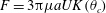 $F=3\unicode[STIX]{x03C0}\unicode[STIX]{x1D707}aUK(\unicode[STIX]{x1D703}_{c})$
, where
$F=3\unicode[STIX]{x03C0}\unicode[STIX]{x1D707}aUK(\unicode[STIX]{x1D703}_{c})$
, where
 $K(\unicode[STIX]{x1D703}_{c})$
is a function of the contact angle for which tables are available (Fischer et al.
Reference Fischer, Dhar and Heinig2006). According to the scaling laws developed in the current paper, one might expect that
$K(\unicode[STIX]{x1D703}_{c})$
is a function of the contact angle for which tables are available (Fischer et al.
Reference Fischer, Dhar and Heinig2006). According to the scaling laws developed in the current paper, one might expect that
 $\unicode[STIX]{x1D706}$
will be approximately proportional to
$\unicode[STIX]{x1D706}$
will be approximately proportional to
 $1/K$
(at least in the relatively dilute limit): for variations in the contact angle such that the particles will protrude more and more into the liquid phase, we expect a reduction in the slip length. This expected behaviour assumes that the fluid interface between the particles is perfectly flat; fluctuations in the interface due to thermal motion could change this picture quite substantially, as discussed by Boniello et al. (Reference Boniello, Blanc, Fedorenko, Medfai, Mbarek, In, Gross, Stocco and Nobili2015). For contact angles close to
$1/K$
(at least in the relatively dilute limit): for variations in the contact angle such that the particles will protrude more and more into the liquid phase, we expect a reduction in the slip length. This expected behaviour assumes that the fluid interface between the particles is perfectly flat; fluctuations in the interface due to thermal motion could change this picture quite substantially, as discussed by Boniello et al. (Reference Boniello, Blanc, Fedorenko, Medfai, Mbarek, In, Gross, Stocco and Nobili2015). For contact angles close to
 $0^{\circ }$
or
$0^{\circ }$
or
 $180^{\circ }$
, one needs to consider that the area fraction as defined in the current paper is not representative of the surface coverage by the particles, as in these limiting cases the particles barely touch the fluid interface.
$180^{\circ }$
, one needs to consider that the area fraction as defined in the current paper is not representative of the surface coverage by the particles, as in these limiting cases the particles barely touch the fluid interface.
While we have started to show evidence for some effects of the microstructure on the slip length by comparing square arrays and mesh-like particle networks, more realistic microstructures should be investigated. These include the regular hexagonal structure of colloidal crystals at fluid interfaces (Irvine, Vitelli & Chaikin Reference Irvine, Vitelli and Chaikin2010) and the fractal structure of percolating networks of aggregated interfacial colloids (Aveyard et al. Reference Aveyard, Clint, Nees and Paunov2000; Poulichet & Garbin Reference Poulichet and Garbin2015).
Acknowledgements
We acknowledge financial support from the European Community through grant no. 618335 ‘FlowMat: Flow and Capillarity in Materials Science’.


