


1 Introduction
In convective heat transfer problems, the most fundamental phenomenon is the motion of buoyant convection from point sources in a stationary fluid. The buoyant convection from point sources has been classified into two main groups: plumes (continuous injection of heat) and thermals (release of heat over a short period of time). Thermals are important in practical applications such as heat transfer from a heated flat plate to a fluid (Sparrow, Husar & Goldstein Reference Sparrow, Husar and Goldstein1970), convection in ice formation (Tankin & Farhadien Reference Tankin and Farhadien1971) and convection in gas absorption in pools of liquid (Thompson Reference Thompson1970).
The dynamics of turbulent thermals occurring for large Rayleigh numbers has been previously studied (Taylor Reference Taylor1946; Batchelor Reference Batchelor1954). Laminar thermals for small Rayleigh numbers have also attracted much attention from researchers since the 1970s. Shlien (Reference Shlien1976), based on experiments, divided the formation of laminar thermals into six stages: heat conduction stage, constant acceleration stage, plume stage, transition to thermal behaviour, similarity stage and diffusion stage. The laminar thermals can form isolated buoyant vortex rings during their development and grow into mushroom-like structures. Shlien & Brosh (Reference Shlien and Brosh1979) experimentally studied the distributions of velocity and vorticity of laminar thermals and found that the ratio of the circulation to the buoyancy force is constant. Shlien & Thompson (Reference Shlien and Thompson1975) studied the shape evolution of laminar thermal caps, and the geometric similarity was analysed. The thermal vortex ring was found to be very stable, and its general character was not affected by small disturbances to the ambient fluid.
The vortex ring has been considered as a basic element of many flows such as the flows generated through jets, plume flows and thermal flows. The formation of vortex rings has been studied widely. Gharib, Rambod & Shariff (Reference Gharib, Rambod and Shariff1998) experimentally studied the formation of vortex rings generated through impulsively started jets. They observed two distinct states, each being dependent on the formation time (defined as the stroke ratio). For a short formation time, almost all of the discharged fluid was finally absorbed into the vortex ring leaving no trailing jet. For a long formation time, the formed leading vortex ring was finally disconnected from the following trailing jet when the pinch-off process was complete. The formation number was defined as the critical formation time corresponding to the transition between the two states and was observed to be approximately 4. The formation number was also proposed to be determined by determining the completion of the pinch-off process. Mohseni & Gharib (Reference Mohseni and Gharib1998) developed a theoretical model to predict the formation number.
This formation number of approximately 4 is universal for the majority of vortex rings. However, some changes in flow conditions can lead to different values of the formation number. Mohseni, Ran & Colonius (Reference Mohseni, Ran and Colonius2001) proposed applying a non-conservative force of long duration to delay of vortex ring pinch-off. Dabiri & Gharib (Reference Dabiri and Gharib2004) used an imposed bulk counterflow for delay of vortex ring pinch-off by approximately 10 %. Dabiri & Gharib (Reference Dabiri and Gharib2005) found that the formation number could increase to approximately 8, if the nozzle exit diameter is changed instantaneously during the formation of the vortex ring. Krueger, Dabiri & Gharib (Reference Krueger, Dabiri and Gharib2006) experimentally studied the formation number of vortex rings formed in uniform background co-flow. When the velocity of the co-flow is higher than 50 % of the jet velocity, the vortex ring occurs very early, almost as soon as the co-flow is initiated.
Buoyancy produced by the density difference between the vortex ring and the ambient fluid can change the flow dynamics and influence the vortex ring pinch-off and the formation number. The vorticity in the core of buoyant vortex rings is comprised of the vorticity relevant to the vortices rolled up into the core and the baroclinic vorticity generated owing to the density gradients (Bond & Johari Reference Bond and Johari2010). Shusser & Gharib (Reference Shusser and Gharib2000) developed a model for vortex ring formation in a buoyant starting plume, and based on Lundgren, Yao & Mansour’s (Reference Lundgren, Yao and Mansour1992) time scale, the formation number reached 4.73. Pottebaum & Gharib (Reference Pottebaum and Gharib2004) experimentally studied the pinch-off process in a buoyant starting plume and the formation number was between 4.4 and 4.9. They suggested that pinch-off is a general component of the vortex ring formation process for various generation mechanisms. Wang et al. (Reference Wang, Law, Adams and Fringer2009) performed large eddy simulations to reproduce buoyant starting jets in conditions ranging from pure jet to lazy plume. They found that the buoyant formation number of a buoyant starting jet increases with larger Richardson number, and is beyond 8 for  $Ri=0.5$ and
  $Re=2500$. While, for negatively buoyant starting jets, the formation number is lowered with the increase of negative buoyancy (Marugán-Cruz, Rodríguez-Rodríguez & Martínez-Bazán Reference Marugán-Cruz, Rodríguez-Rodríguez and Martínez-Bazán2013; Gao & Yu Reference Gao and Yu2016).
Bond & Johari (Reference Bond and Johari2005) experimentally investigated the effect of the aspect ratios of cylindrical tubes ranging from 2 to 8 on the thermal development for different values of the initial Richardson number from 0.6 to 1.6. They observed an interesting flow phenomenon for cylindrical tubes of aspect ratio 6 that the fluid at the leading edge rolled up into a secondary ring-like structure and the starting vortex was effectively replaced. The occurring regimes and conditions of the interesting phenomenon are still unknown. No further research on the phenomenon has been reported. An interesting question is whether the new vortex structure leads to the changes of the vortex ring pinch-off and the formation number. In this paper, three-dimensional direct numerical simulations of laminar thermals are performed for different Richardson numbers and different injection durations, the formation regimes and conditions of the vortex rings and the formation number are studied. Finally, the effects of the Richardson number and the injection duration on the formation number are analysed.
2 Methods
We perform direct numerical simulations of laminar thermals reproducing the piston–cylinder arrangement. Figure 1 shows a sketch of the computational domain of the thermal flow and the boundary conditions. Thermal fluid with a temperature  $T_{0}$ flows at a velocity
  $U_{0}$ through a small circular orifice with the diameter
  $D$ into a homogeneous and stationary ambient fluid with the temperature
  $T_{amb}$ over a short period of time
  $t_{i}^{\ast }$. The use of the three-dimensional model is to observe whether the thermals remain axisymmetric or not before and during the pinch-off process of vortex rings in all cases.

Figure 1. Sketch of the computational domain of a thermal flow and the boundary conditions.
We non-dimensionalize all the parameters as follows:
 $$\begin{eqnarray}\displaystyle \left.\begin{array}{@{}c@{}}x=x^{\ast }/D,\quad y=y^{\ast }/D,\quad z=z^{\ast }/D,\quad t=t^{\ast }U_{0}/D,\quad p=p^{\ast }/(\unicode[STIX]{x1D70C}U_{0}^{2}),\\ u=u^{\ast }/U_{0},\quad v=v^{\ast }/U_{0},\quad w=w^{\ast }/U_{0},\quad \unicode[STIX]{x1D703}=(T^{\ast }-T_{amb})/\unicode[STIX]{x0394}T,\end{array}\!\right\} & & \displaystyle\end{eqnarray}$$
 where ( $u,v,w$) is the dimensionless velocity in Cartesian coordinates (
 $x,y,z$),
  $p$ is the dimensionless pressure,
  $t$ is the dimensionless time and
  $\unicode[STIX]{x1D703}$ is the dimensionless temperature. The temperature difference between the injected thermal fluid and the ambient fluid is
  $\unicode[STIX]{x0394}T=T_{0}-T_{amb}$.
The fluid flow and heat transfer for the thermals are described using the three-dimensional incompressible Navier–Stokes equations in Cartesian coordinates with the Boussinesq approximation, which can be expressed in the dimensionless form of
 $$\begin{eqnarray}\displaystyle & \displaystyle \unicode[STIX]{x1D735}\boldsymbol{\cdot }\boldsymbol{u}=0, & \displaystyle\end{eqnarray}$$
 $$\begin{eqnarray}\displaystyle & \displaystyle {\displaystyle \frac{\unicode[STIX]{x2202}\boldsymbol{u}}{\unicode[STIX]{x2202}t}}+\boldsymbol{u}\boldsymbol{\cdot }\unicode[STIX]{x1D735}\boldsymbol{u}=-\unicode[STIX]{x1D735}\boldsymbol{p}+{\displaystyle \frac{1}{Re}}\unicode[STIX]{x1D6FB}^{2}\boldsymbol{u}+Ri\unicode[STIX]{x1D703}\boldsymbol{e}_{y}, & \displaystyle\end{eqnarray}$$
 $$\begin{eqnarray}\displaystyle & \displaystyle {\displaystyle \frac{\unicode[STIX]{x2202}\unicode[STIX]{x1D703}}{\unicode[STIX]{x2202}t}}+\boldsymbol{u}\boldsymbol{\cdot }\unicode[STIX]{x1D703}={\displaystyle \frac{1}{Pr\cdot Re}}\unicode[STIX]{x1D6FB}^{2}\unicode[STIX]{x1D703}, & \displaystyle\end{eqnarray}$$
 where  $\boldsymbol{u}=(u_{x},u_{y},u_{z})$ and
  $\boldsymbol{e}_{y}$ is the unit vector (0,1,0). The dimensionless parameters are defined as follows: Reynolds number
  $Re=U_{0}D/\unicode[STIX]{x1D708}$, Prandtl number
  $Pr=\unicode[STIX]{x1D708}/\unicode[STIX]{x1D6FC}$ and Richardson number
  $Ri=g\unicode[STIX]{x1D6FD}D\unicode[STIX]{x0394}T/U_{0}^{2}$, where
  $\unicode[STIX]{x1D6FD}$ is the volumetric thermal expansion coefficient of the fluid.
The velocity in the  $y$ direction and the temperature at the circular orifice are considered to be uniform. The forcing conditions are written as
 $$\begin{eqnarray}\left.\begin{array}{@{}c@{}}u=0,\quad v=1,\quad w=0,\quad \unicode[STIX]{x1D703}=1,\quad t\leqslant t_{i},x^{2}+z^{2}<0.25,\\ u=0,\quad v=0,\quad w=0,\quad \unicode[STIX]{x1D703}=0,\quad t>t_{i},x^{2}+z^{2}<0.25,\\ u=0,\quad v=0,\quad w=0,\quad \unicode[STIX]{x1D703}=0,\quad x^{2}+z^{2}\geqslant 0.25,\end{array}\!\right\}\end{eqnarray}$$
 where  $t_{i}$ is the dimensionless injection duration of the thermal fluid given by
  $t_{i}=t_{i}^{\ast }U_{0}/D$. No-slip velocity boundary conditions are employed at the sides of the computational domain
 $$\begin{eqnarray}\displaystyle u=0,\quad v=0,\quad w=0,\quad \unicode[STIX]{x1D703}=0. & & \displaystyle\end{eqnarray}$$
 The boundary conditions at the exit at  $y=60$ are
 $$\begin{eqnarray}\displaystyle \displaystyle \frac{\unicode[STIX]{x2202}u}{\unicode[STIX]{x2202}y}=0,\quad {\displaystyle \frac{\unicode[STIX]{x2202}v}{\unicode[STIX]{x2202}y}}=0,\quad {\displaystyle \frac{\unicode[STIX]{x2202}w}{\unicode[STIX]{x2202}y}}=0,\quad {\displaystyle \frac{\unicode[STIX]{x2202}\unicode[STIX]{x1D703}}{\unicode[STIX]{x2202}y}}=0. & & \displaystyle\end{eqnarray}$$
The above equations and the initial and boundary conditions are solved with the open-source code Gerris, which implements a multilevel Poisson solver and adaptive quad/octree spatial discretization using a finite-volume approach (Popinet Reference Popinet2003, Reference Popinet2009). A second-order accurate upwind scheme is utilized to discretize the advection terms. The Crank–Nicholson discretization of the viscous terms is implemented, which is formally second-order accurate and unconditionally stable (Popinet Reference Popinet2009). The dynamic adaptive refinement of the mesh is conducted according to different physical criteria.
In this paper, two refinement criteria are simultaneously used: one criterion based on the local value of the vorticity, and another based on the gradient of temperature. Each cell without any child cells will be refined once the vorticity criterion
 $$\begin{eqnarray}\displaystyle {\displaystyle \frac{|\unicode[STIX]{x1D735}\times \boldsymbol{u}|\unicode[STIX]{x1D6E5}}{\max (|\boldsymbol{u}|)}}>\unicode[STIX]{x1D6FF}_{1}, & & \displaystyle\end{eqnarray}$$
or the temperature gradient criterion
 $$\begin{eqnarray}\displaystyle |\unicode[STIX]{x1D735}\unicode[STIX]{x1D703}|\unicode[STIX]{x1D6E5}>\unicode[STIX]{x1D6FF}_{2}, & & \displaystyle\end{eqnarray}$$
 is satisfied, where  $\unicode[STIX]{x1D6E5}$ is the dimensionless side length of the cell, and the thresholds
  $\unicode[STIX]{x1D6FF}_{1}$ and
  $\unicode[STIX]{x1D6FF}_{2}$ are set to 0.01 and 0.001 respectively in this paper.
In Gerris, the mesh refinement process starts from the initial root cells, and the refinement level of an initial root cell is 0. To refine once is to divide each cell into four child cells in two dimensions or eight in three dimensions, and simultaneously the refinement level of the child cells is equal to that of their parent cell plus 1. Keep refining the cell tree until the refinement level of the minimum cell is equal to the maximum  $L_{max}$. We specify the dimensionless side length of an initial root cell as 20, and set the minimum refinement level (implemented regardless of the refinement criteria) to 6. The grid independence analysis is performed for different maximum refinement levels of
  $L_{max}=9$, 10 and 11 for the thermals with
  $Ri=4$ and
  $t_{i}=2.5$. The results for
  $L_{max}=10$ are very close to those for
  $L_{max}=11$, so the maximum refinement level of
  $L_{max}=10$ is chosen in the following simulations. In this case, the minimum dimensionless size of the grids is equal to 20/210 (≈0.02).
The number of grids and the computational cost increase greatly with time due to the implementation of the adaptive mesh refinement method. For example, for  $Ri=1.5$ and
  $t_{i}=3$, the total numbers of grid points are 0.817 million at
  $t=0,4.094$ million at
  $t=7$ and 5.783 million at
  $t=9$, respectively. Twelve cores are used for computation in every case. The CPU times (on a single CPU 2.3 GHz 64 bit Intel Xeon processor) are 13.3 h from
  $t=0$ to
  $t=7$, and 21.4 CPU hours from
  $t=0$ to
  $t=9$, respectively. Figure 2 is an exploded view of the temperature front of
  $\unicode[STIX]{x1D703}=0.05$ at
  $t=4$ for
  $Ri=2$ and
  $t_{i}=2$. It is seen from this figure that our findings do not suffer from spurious numerical dispersion and the ringing effects along fine interfaces.

Figure 2. An exploded view of the temperature front of  $\unicode[STIX]{x1D703}=0.05$ at
  $t=4$ for
  $Ri=2$ and
  $t_{i}=2$.
3 Development of thermal cap and buoyant vortex rings
In this paper, the Richardson number and the injection duration are changed and the Reynolds number and the Prandtl number are kept constant:  $Re=100$ and
  $Pr=7$. The computational cases are presented in table 1. We run our simulations in non-dimensional coordinates. A ballpark estimate of some of the physical parameters for
  $Ri=1$ is presented for comparison with the experimental parameters based on an assumption of the use of water as the experimental fluid:
  $D=0.95~\text{cm}$ and
 $U_{0}=1.969~\text{cm}~\text{s}^{-1}$.
Table 1. Richardson numbers and fluid injection durations for the computational cases.

Figure 3 shows the shape evolution of the thermal caps for  $t\leqslant 6$ for the two typical cases: case I (
 $Ri=1.5$,
  $t_{i}=2$) and case II (
 $Ri=1.5$,
  $t_{i}=3$). In this figure, the thermal cap is formed after the fluid is injected inward and then stretches in the direction of flow due to the buoyant acceleration. Since the injection duration for case II is longer, the cap for case II is obviously longer than that for case I at
  $t=6$, but the diameters of the caps for the two cases are nearly equal. This indicates that the thermal cap can be altered by the injection duration when developing over enough time.

Figure 3. Shape evolution of the thermal caps represented by the temperature contour plots in the longitudinal section of  $z=0$ for
  $t\leqslant 6$ for two typical cases: (a)
  $Ri=1.5$,
  $t_{i}=2$; (b)
  $Ri=1.5$,
  $t_{i}=3$.
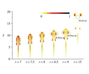
For longer injection duration, the quantity of heat of the thermal is larger, and the length-to-diameter ratio of the cap is larger, meaning it is easier to cause a change of the thermal cap structure when the cap continues stretching. As shown in figure 4(a), at  $t=7$ for case II, the rim of the cap starts to bend inward. At
  $t=8.5$, the fluid at the leading edge rolls up into a secondary vortex ring structure and the starting vortex ring is effectively replaced. The observation agrees well with the phenomenon observed in Bond & Johari’s (Reference Bond and Johari2005) experiments. In figure 4(a), only a part of the thermal fluid in the starting vortex rolls up into the secondary vortex ring structure and, at
  $t=15$, the starting vortex has been broken up into two parts. Larger Richardson number causes larger buoyancy, which also makes it easier to induce a change of the thermal cap structure. A typical case III (
 $Ri=2$,
  $t_{i}=2$) with larger Richardson number than case I is shown in figure 4(b). The overall character of the behaviour of the thermal cap is similar to the case II, but one apparent difference is that nearly all thermal fluid in the starting vortex rolls up into the secondary vortex ring structure.

Figure 4. Shape evolution of the thermal caps represented by the temperature contour plots for  $t\geqslant 7$ for two typical cases: (a)
  $Ri=1.5$,
  $t_{i}=3$; (b)
  $Ri=2$,
  $t_{i}=2$. The temperature contour plots in the longitudinal section of
  $z=0$ are at
  $t=7$, 7.5, 8, 8.5, 9 and 15 in sequence.
During the development of the thermal caps, a longer injection duration and a larger Richardson number lead to two new modes of thermals: the mode with the occurrence of the secondary vortex ring without breakup, and the mode with the occurrence of the secondary vortex ring with breakup. Case I is a case of the starting vortex ring dominated mode. The features and differences of the three modes will be discussed in detail using the vorticity isolines during the development of thermals over a very long time.
Figure 5 illustrates the growth of buoyant vortex rings and eventual pinch-off for the three typical thermal modes. As shown in figure 5(a), for the typical case I, the vortical structures at  $t=6$, 8, 12, 18 and 24 are axisymmetric. At
  $t=12$, the buoyant vortex ring is clearly separated from the trailing shear layer, implying that the vortex ring pinch-off has been completed. With further development, the diameter of pinched off vortex ring becomes larger, and the vorticity of trailing shear layer becomes smaller due to the diffusion effect.

Figure 5. Vorticity isolines in the longitudinal section of  $z=0$ at
  $t=6$, 8, 12, 18 and 24 for the three typical thermal cap modes. (a)
  $Ri=1.5$,
  $t_{i}=2$; (b)
  $Ri=2$,
  $t_{i}=2$; (c)
  $Ri=1.5$,
  $t_{i}=3$. The vorticities of the isolines are respectively equal to
  $\pm 80\,\%$,
  $\pm 60\,\%$,
  $\pm 40\,\%$,
  $\pm 20\,\%$ and
  $\pm 4\,\%$ of the maximum vorticity in the flow field.
Compared to the typical case I, the vortical structure for the typical case III is more slender, as shown in figure 5(b). At  $t=8$, a new vortex structure is formed. The new vortex as the leading vortex gradually absorbs the circulation from the starting vortex. With the vortex rising, the starting vortex is engulfed by the leading vortex at
  $t=12$ and the resulting vortical structure becomes stable. The pinch-off of the buoyant vortex ring has been completed at
  $t=18$. Compared to case I, the pinch-off is found to occur later. The delay of pinch-off is possibly attributed to the reconstruction of the vortical structure.
The overall character of the restructuring behaviour of the vortical structure for the typical case II is similar to the typical case III. Different from case III, the vortical structure has been broken up into two parts, and the vortex ring pinch-off has been completed, at  $t=24$ as shown in figure 5(c). The distance between the core of the new vortex and the core of the starting vortex is larger. This determines that, with the thermal development, only a part of the vorticity of the starting vortex is absorbed by the leading vortex and the remaining vorticity is disconnected from the vorticity field of the pinched off vortex ring. The pinch-off of the buoyant vortex ring is delayed compared to the typical cases I and III, because it takes the longest time to complete the complex reconstruction process of the vortical structure. With the further development of the thermal, the remaining vorticity also becomes disconnected from the trailing shear layer below. Analysis of instability is beyond the scope of this paper.

Figure 6. Boundary between non-occurrence and occurrence of the secondary vortex ring in a (Ri,  $t_{i}$) space for
  $Re=100$ and
  $Pr=7$. Red squares represent the non-occurrence of the secondary vortex ring (NSVR), and the blue line white triangles represent the occurrence of the secondary vortex ring (OSVR) without breakup and green triangles represent the OSVR with breakup. Black solid line is the boundary line of NSVR and OSVR. The other seven computational cases in table 1 used in figure 8 are a little far from the boundary and therefore are not included here.
As previously mentioned, the structure of the thermal cap is related to the Richardson number Ri and the injection duration  $t_{i}$. The development modes of the thermal cap are effectively determined by these two parameters. The boundary of non-occurrence and occurrence of the secondary vortex ring is determined in a (Ri,
  $t_{i}$) space and shown in figure 6. The region for the regime with the occurrence of the secondary vortex ring without breakup is very narrow, which is considered as a transition state. For
  $Ri<0.6$, even when
  $t_{i}$ increases to 10, the thermals are still dominated by the starting vortex ring. This is reasonable, because thermal flow with very small Richardson number and very long injection duration approximates a starting plume and the cap structure is stable. The behaviour of laminar thermals can be described by the effective Rayleigh number:
  $Ra_{m}=g\unicode[STIX]{x1D6FD}Q/(\unicode[STIX]{x1D70C}c\unicode[STIX]{x1D6FC}\unicode[STIX]{x1D708})$, where the total heat injected is given by
  $Q=c\unicode[STIX]{x1D70C}U_{0}t_{i}^{\ast }\unicode[STIX]{x0394}T\unicode[STIX]{x03C0}D^{2}/4$, where
  $c$ is the specific heat capacity (Shlien Reference Shlien1976). The effective Rayleigh number can be further written as:
  $Ra_{m}=(\unicode[STIX]{x03C0}/4)Re^{2}PrRit_{i}$. The effective Rayleigh number may be considered as a ratio of the buoyancy effects to viscous and diffusive effects (Shlien Reference Shlien1976). Larger effective Rayleigh number than the critical value can lead to the occurrence of the secondary vortex ring. The critical effective Rayleigh number approximating to 1. 95 × 105, corresponding to the oblique straight line segment of the boundary in figure 6 for the occurrence of the secondary vortex ring, is only suitable for
  $Ri>0.7$ and
  $t_{i}<5$.
4 Determination of formation number of buoyant vortex rings
The circulation of a vortex ring of thermals originates from two sources, i.e. the initial circulation  $\unicode[STIX]{x1D6E4}_{0}$ and the buoyancy-induced circulation
  $\unicode[STIX]{x1D6E4}_{B}$. The characteristic time scale required for a buoyant jet to travel a distance of one diameter from an orifice or nozzle in combination of the initial momentum and buoyancy fluxes (Wang et al. Reference Wang, Law, Adams and Fringer2009) is used here:
 $$\begin{eqnarray}\hat{t}=\frac{D}{\sqrt{U_{0}^{2}+2gD\unicode[STIX]{x0394}\unicode[STIX]{x1D70C}/\unicode[STIX]{x1D70C}}},\end{eqnarray}$$
 where  $\unicode[STIX]{x0394}\unicode[STIX]{x1D70C}$ is the density difference between the ambient fluid and the vortex ring given by
  $\unicode[STIX]{x0394}\unicode[STIX]{x1D70C}=\unicode[STIX]{x1D70C}_{amb}-\unicode[STIX]{x1D70C}$. For the Boussinesq approximation, the relationship is obtained as
  $\unicode[STIX]{x0394}\unicode[STIX]{x1D70C}/\unicode[STIX]{x1D70C}=\unicode[STIX]{x1D6FD}\unicode[STIX]{x0394}T$. In this case, the above equation can be rewritten as
 $$\begin{eqnarray}\hat{t}=\frac{D/U_{0}}{\sqrt{1+2Ri}}.\end{eqnarray}$$
The formation time is obtained as (Wang et al. Reference Wang, Law, Adams and Fringer2009)
 $$\begin{eqnarray}\unicode[STIX]{x1D70F}=t^{\ast }/\hat{t}=t\cdot \sqrt{1+2Ri}.\end{eqnarray}$$
 We estimate the formation number of the vortex ring of thermals by using Gharib et al.’s (Reference Gharib, Rambod and Shariff1998) method based on (4.3). The formation number for the vortex ring of thermals is determined as  $F=\unicode[STIX]{x1D70F}(\unicode[STIX]{x1D6E4}_{t}=\unicode[STIX]{x1D6E4}_{vr,p})$, where the formation time corresponds to the value of the total circulation
  $\unicode[STIX]{x1D6E4}_{t}$, which is equal to the vortex ring circulation
  $\unicode[STIX]{x1D6E4}_{vr,p}$ when the pinch-off ends. The vortex ring circulation based on the completion of pinch-off of the head vortex ring is first determined, and then the formation time corresponding to the total circulation being equal to the vortex ring circulation is obtained as the formation number. We take the typical case III as an example to determine the formation number of 6, as shown in figure 7(a). This formation number is beyond the universal formation number of 4 for non-buoyant vortex rings. This is attributed to the buoyant effect. Identification of the boundary of the vortex ring has a certain influence on the total circulation, the vortex circulation and the vortex ring pinch-off time. The cutoff percentage determines the boundary of the vortex ring. The increase of the cutoff percentage leads to an increase of circulation of the pinched off vortex ring and a small increase of the formation number, as shown in figure 7(b).

Figure 7. (a) Evolution of the total circulation and the vortex circulation and (b) the circulation of the pinched off vortex ring and the formation number (F) for different cutoff percentages ( $Ri=2$,
  $t_{i}=2$). In (a), the formation time for pinch-off is
  $\unicode[STIX]{x1D70F}=33.5$.
In order to illustrate the effect of the thermal modes on the formation number, we plot the pinched off vortex ring circulations and the formation numbers for different values of injection duration and Richardson number, as shown in figure 8. Longer injection duration can lead to increases of  $\unicode[STIX]{x1D6E4}_{0}$ and
  $\unicode[STIX]{x1D6E4}_{B}$, and increases of the pinched off vortex ring circulation and the formation number (figure 8a). Larger Richardson number causes an increase of buoyancy-induced circulation
  $\unicode[STIX]{x1D6E4}_{B}$, which results in larger pinched off vortex ring circulation and a small increase of the formation number (figure 8b). As shown in figure 6, when
  $t_{i}$ is beyond the boundary value between 3.25 and 3.5 for
  $Ri=1$, or when Ri is beyond the boundary value between 1.5 and 2 for
  $t_{i}=2$, the secondary vortex ring will occur for the thermal. However, the switching of the thermal modes is not found from figure 8 to cause an abrupt change of the formation number. This is because the cessation of absorption of the fluid of the trailing jet into the head vortex ring is mainly determined by the circulation requirement of the head vortex ring, which is nearly independent of the thermal mode and the trailing jet.

Figure 8. Effects of (a) the injection duration and (b) the Richardson number on the pinched off vortex ring circulation and the formation number. In (a), the Richardson number is kept constant:  $Ri=1$, the injection duration varies from 2 to 6 at an interval of 0.5 and the formation number increases from 5.4 to 7.8. In (b), the injection duration is kept constant:
  $t_{i}=2$, the Richardson number varies from 1 to 4 at an interval of 0.5 and the formation number increases from 5.4 to 6.4.
5 Conclusions
In this paper, the formation regimes and flow stability of vortex rings in thermals are studied numerically for  $Re=100$ and
  $Pr=7$. The formation number of the vortex rings in thermals is then analysed. The following conclusions are drawn.
(a) Three thermal modes are observed: the starting vortex ring dominated mode, the mode with the occurrence of the secondary vortex ring with breakup and the mode with the occurrence of the secondary vortex ring without breakup. The thermal caps in all the three modes stretch in the flow direction due to the buoyant acceleration. When the cap is stretched long enough, the fluid at the leading edge will roll up into the secondary vortex ring structure and the cap is restructured. If only a part of vorticity of the starting vortex is absorbed by the leading vortex (i.e. the new vortex), the rolling-up will be accompanied by the breakup of the vortical structure into two parts. Or else, the starting vortex will be engulfed by the leading vortex. Whether the vortical structure breaks up may be determined by the distance between the core of new vortex and the core of starting vortex.
(b) The boundary of non-occurrence and occurrence of the secondary vortex ring in a (Ri,  $t_{i}$) space is determined. The region for the occurrence of the secondary vortex ring without breakup is very narrow. For
  $Ri<0.6$, the secondary vortex ring does not occur even for very long injection duration. The effective Rayleigh number (
 $Ra_{m}$) is proposed to accommodate the cases
  $Ri>0.7$ and
  $t_{i}<5$, with the effective Rayleigh number larger than the critical value (approximates to 1. 95 × 105) for the occurrence of the secondary vortex ring.
(c) In the effect of the reconstruction of the vortical structure due to the occurrence of the secondary vortex ring, the vortex ring pinch-off is delayed. The delay of vortex ring pinch-off is the most serious for the mode with the occurrence of the secondary vortex ring with breakup.
(d) The formation number of buoyant vortex rings is beyond the universal formation number of 4 for non-buoyant vortex rings. The formation number increases rapidly with longer injection duration and increases slowly with larger Richardson number. Although changing the formation process of the vortex rings, the switching of the thermal modes due to the occurrence of the secondary vortex ring has little influence on the formation number.
Acknowledgements
This research was supported in part by the National Natural Science Foundation of China (no. 11672116).
Declaration of interests
The authors report no conflict of interest.


