Introduction
Modern wireless communication systems including Wireless Local Area Network (WLAN) and Worldwide interoperability for Microwave Access (WiMAX) are heading toward designing the characteristics of compact size, multiband, greater impedance bandwidth (super band antenna), and omnidirectional pattern [Reference Balanis1–Reference Krishna, Gopikrishna, Aanandan, Mohanan and Vasudevan3]. Designing antenna structures considering the above-mentioned features is regarded as a major challenge [Reference Huang, Liu, Zhang and Gong2–Reference Moosazadeh and Kharkovsky4].
The metamaterials (MTMs) are used in various structures to provide multiband and multifunctional demanded features as well as increased bandwidth property [Reference Nourbakhsh, Zareian-Jahromi and Basiri5, Reference Nemat-Abad, Zareian-Jahromi and Basiri6]. The adaption of composite right/left-handed (CRLH) MTMs or simply MTM unit cells can lead to improved antennas such as enhanced leaky-wave antennas [Reference Jackson, Caloz and Itoh7], multifunctional antennas [Reference Zhu, Li, Li, Su, Wang, Zhai, Li and Liang8], and resonator-type antennas [Reference Ha, Kwon, Lee and Choi9, Reference Amani and Jafargholi10].
Low cost, low profile, and multiband operating capability features of monopole planar structures make them a good candidate for WLAN and WiMAX applications. The negative order resonances and reduced resonance frequencies of MTM microstrip patch antennas result in size reduction and antenna miniaturization [Reference Dong, Toyao and Itoh11, Reference Antoniades and Eleftheriades12]. Moreover, the multi-frequency properties of MTM loaded antennas make them adequate for multiband applications [Reference Zhu, Li, Li, Su, Wang, Zhai, Li and Liang8, Reference Zhu, Antoniades and Eleftheriades13].
In this paper, a low profile CRLH loaded monopole antenna is proposed for 3G, 2.4 GHz WLAN, and 2.55 GHz WiMAX (2.02–2.62 GHz), 3.5 GHz WiMAX (3.48–4.56 GHz), and 5.2 GHz WLAN (5.12–5.34 GHz) applications. To reduce the fabrication cost, a via-free CRLH unit cell is taken into account. In comparison with a simple unloaded antenna, the utilized MTM loading leads to distinct frequency bands with wide frequency bandwidths. A full-wave simulator based upon the finite-element method solutions of Maxwell's equations is used in design procedure. Also, the equivalence circuit model of the proposed structure is proposed [Reference Antoniades and Eleftheriades12–Reference Caloz and Itoh14]. The proposed MTM loaded antenna is fabricated whereas corresponding measurements are compared with simulation results to ensure the enhanced performance characteristics.
The paper is organized as follows. In section “Antenna design”, the antenna design procedure is briefly described. In section “Equivalent circuit”, equivalent circuit of the proposed antenna has been extracted. The current distributions of the proposed antenna are discussed in section “Current distribution”. In section “Experimental results”, the measurement results of the proposed antenna are presented whereas conclusion remarks are presented in section “Conclusion”.
Antenna design
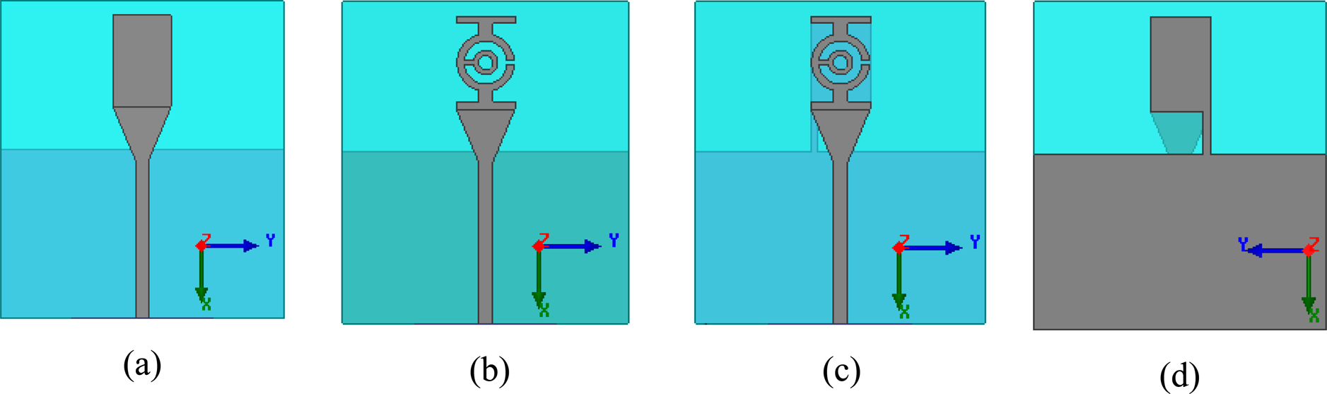
The various design schematic evolutions of the proposed tri-band antenna are shown in Fig. 1. All simulations and fabrications are based on the utilization of an FR4 substrate with a thickness of h = 1 mm, relative electric permittivity of ɛ r = 4.4, and tanδ = 0.02. The design procedure is detailed as follows.

Fig. 1. Design evolution for the proposed tri-band MTM antenna; (a) unloaded monopole antenna; (b) replacing patch with ring resonator; proposed tri-band antenna with single-cell MTM loading: (c) top view and (d) bottom view.
Unloaded monopole antenna
First, an unloaded monopole antenna is investigated to provide a primary structure to which the next modified antennas are compared. The monopole structure is demonstrated in Fig. 1(a) in which the feed line is separated by a slot from the radiating patch. The corresponding reflection coefficient is investigated in Fig. 2 resulting in |S11|<−10 dB at 2.95–4.32 GHz with a resonant frequency of 3.64 GHz.
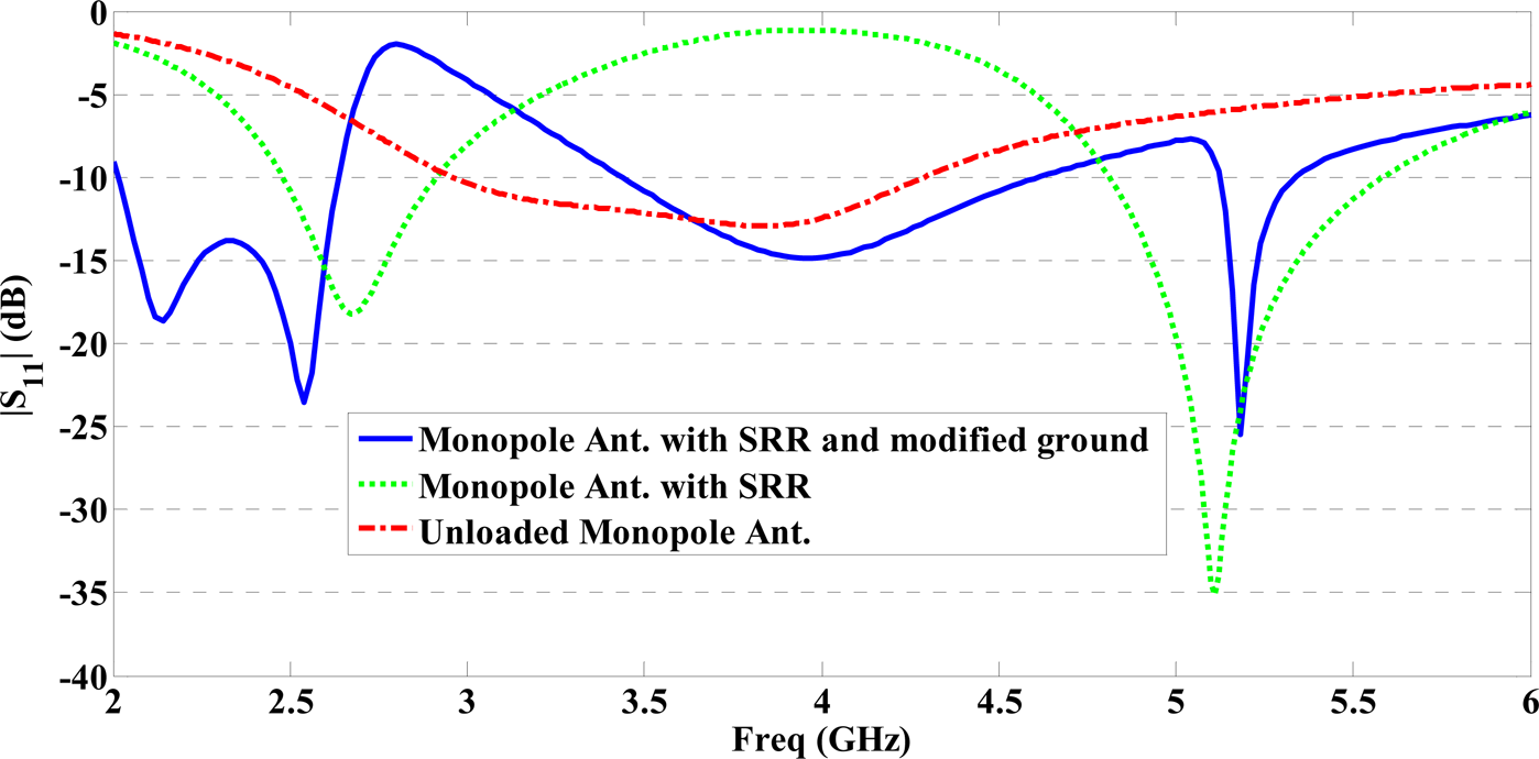
Fig. 2. Simulated return loss of different antenna configurations in Fig. 1.
Dual-band monopole antenna with a ring resonator
The first modified antenna is obtained by replacing the radiating patch in Fig. 1(a) with a ring resonator demonstrated in Fig. 1(b). Two distinct frequency bandwidths of about 430 and 750 MHz with corresponding resonance frequencies of around 2.68 and 5.11 GHz are obtained. Therefore, dual-band operation is achieved together with 26% antenna geometry compactness.
Authors of articles published in the journal assign copyright to Cambridge University Press and the European Microwave Association (with certain rights reserved), and a copyright assignment form must be completed on acceptance of your paper.
Proposed tri-band monopole antenna with MTM loading
In order to obtain a tri-band antenna and achieve more compactness, the final configuration is proposed in Figs 1(c) and 1(d) based on MTM loading. According to Fig. 2, the proposed antenna operates around 2.32 GHz (2.02–2.62 GHz), 4.02 GHz (3.48–4.56 GHz), and 5.23 GHz (5.12–5.34 GHz). In addition to tri-band performance achievement, a compactness of 32% is achieved considering the first resonance frequency.
The geometry parameters of the proposed MTM loaded monopole antenna is demonstrated in Fig. 3. The full size of the introduced monopole antenna is L × W × h mm3 whereas the overall size of the radiating patch is Lr × Wr mm2. According to Fig. 3(a), a slot separates the feed line from the ring resonator as the main radiator. Moreover, the embedded MTM structure is realized through an inductive thin strip connecting the rectangular patch to the ground plane.

Fig. 3. Geometry parameters of the proposed MTM loaded monopole antenna: (a) top view and (b) bottom view.
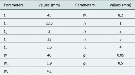
These geometry parameters are optimized to achieve demanded applicability for 3G, WLAN, and WiMAX applications. Moreover, the best geometry compactness is also considered. The finalized geometry parameters of the proposed MTM loaded antenna are listed in Table 1.
Table 1. Dimensions of the proposed MTM antenna in Fig. 3
Equivalent circuit
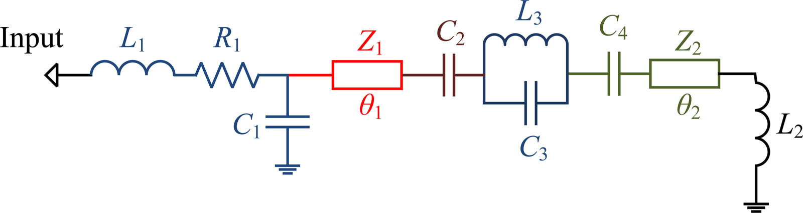
Here, the equivalent circuit model of the proposed via-free antenna is investigated [Reference Antoniades and Eleftheriades12, Reference Zhu, Antoniades and Eleftheriades13, Reference Jamilan, Antoniades, Nourinia and Azarmanesh15, Reference Baena, Bonache, Martín, Sillero, Falcone, Lopetegi, Laso, Garcia-Garcia, Gil, Portillo and Sorolla16]. According to Fig. 4, a CRLH structure is obtained. Corresponding to Fig. 3, the strip located at the antenna base is defined by L1 and R1 whereas C1 is considered to model the capacitance between this inductive strip and ground plane. Moreover, the antenna radiation loss is modeled with a resistance merged in R1. The tapered strip at the end part of feed line is modeled through a transmission line defined by Z1 and θ1. The embedded slot between tapered strip line and ring resonator results in a left-handed series capacitance, C2, whereas the ring resonator is modeled as a parallel tank circuit including inductance L3 and capacitance C3.

Fig. 4. Equivalent circuit model of the proposed antenna in Fig. 3.
The capacitance between the SRR and the rectangular patch beneath it at the ground plane is modeled by C4. Moreover, the mentioned rectangular patch at the ground plane is defined by a transmission line represented by Z2 and θ2. Finally, L2 is yielded from the resulting current flow on an inductive thin strip connecting mentioned rectangular patch to the ground plane. The circuit elements C2, C3, C4, and L2 provide the left-hand property of the proposed antenna.
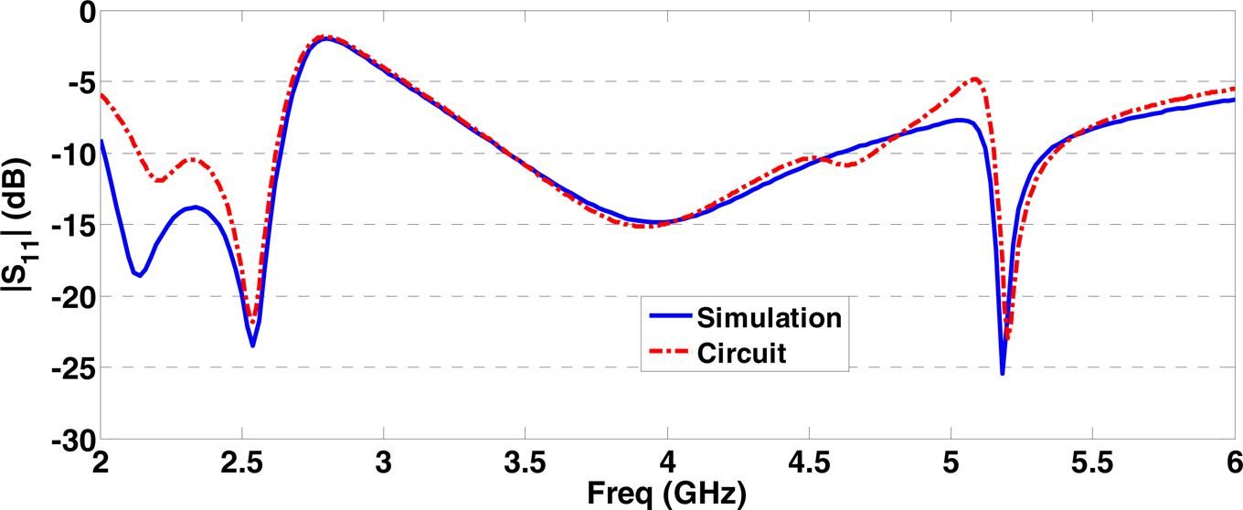
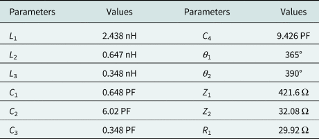
The corresponding values of these circuit elements are optimized to achieve the best reflection coefficient in comparison to simulations. The finalized extracted values for these circuit elements are detailed in Table 2. The reflection coefficient of the introduced antenna is demonstrated in Fig. 5. A good agreement between simulations performed by HFSS software and those obtained by the present circuit model can be found in Fig. 5. The observed differences can be justified as the disability of the circuit model for considering antenna radiation and simplified couplings and losses presented in Fig. 4.

Fig. 5. Return loss corresponding to extracted equivalent circuit in Fig. 4.
Table 2. Values of circuit elements in Fig. 4

Current distribution
Current distributions on the proposed antenna at three resonant frequencies, 2.12, 4.12, and 5.16 GHz are demonstrated in Fig. 6. It is known that left-hand property overcomes right-hand feature at low frequencies in MTM structures. The beneficial effect of the inclusion of the left-handed structure is observed at 2.12 GHz. The inductive thin strip and embedded slot corresponding to L2 and C2, respectively, are mainly involved according to Fig. 6(a).
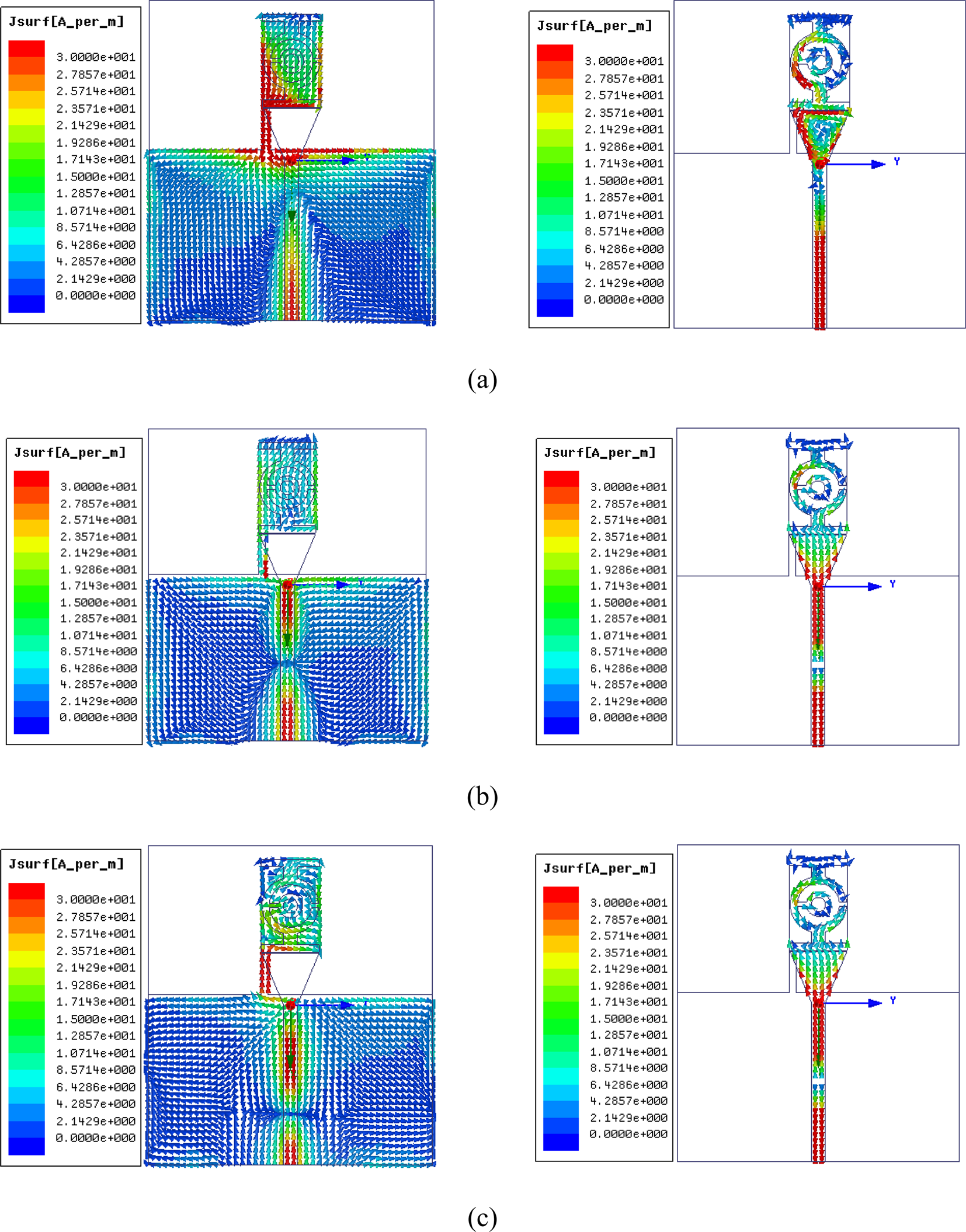
Fig. 6. Current distribution on the proposed antenna in Fig. 3 for three resonant frequencies (a) 2.12 GHz, (b) 4.12 GHz, and (c) 5.16 GHz.
Moreover, the proposed antenna behaves as a CRLH structure at higher frequencies of 4.12 and 5.16 GHz, which is in accordance with current distributions demonstrated in Figs 6(b) and 6(c). According to Fig. 6, the main surface currents are along the x-axis representing x-directed dipole radiating elements. Therefore, a dipole-like radiation pattern is expected.
Experimental results
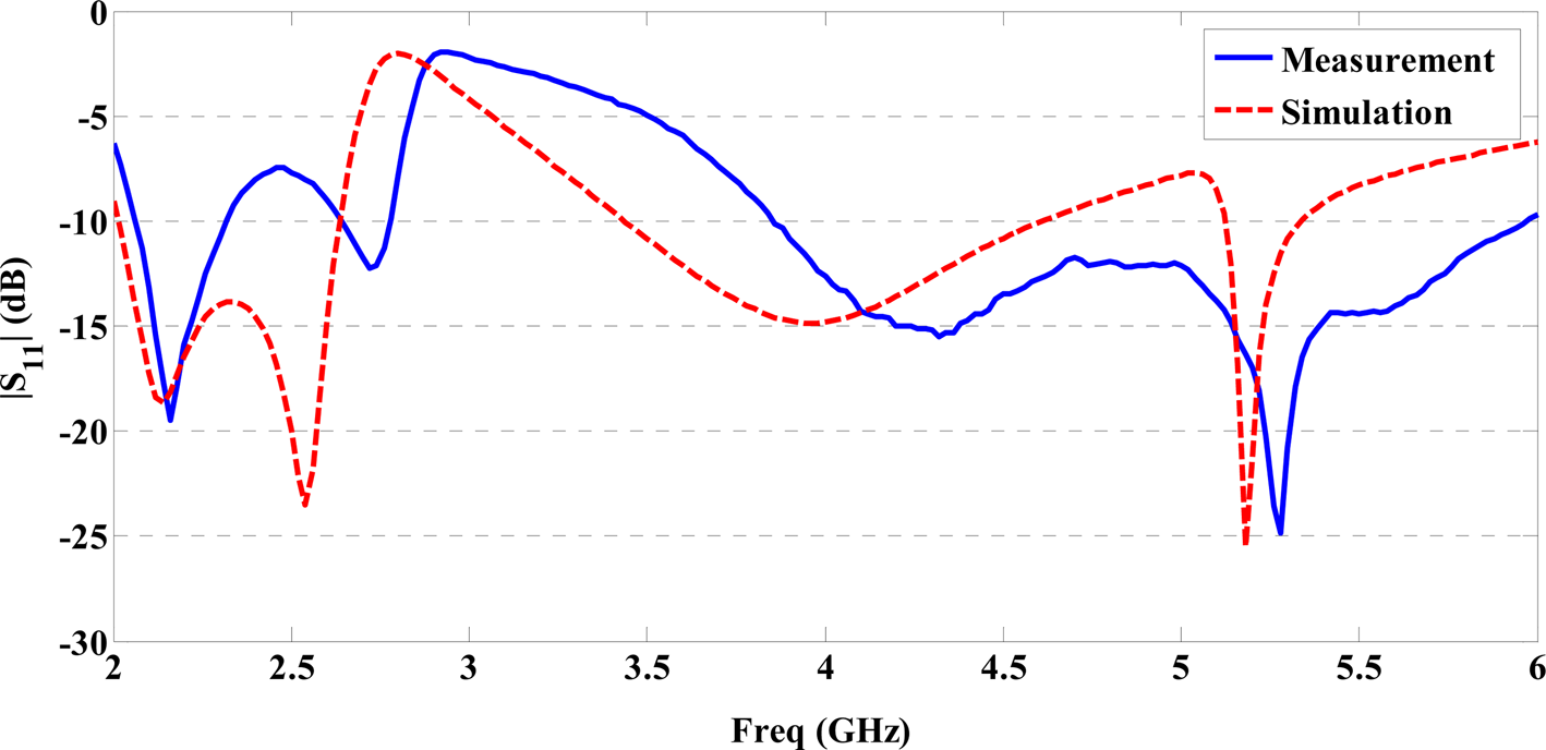
The proposed MTM-loaded tri-band monopole antenna is fabricated on an FR4 substrate with a relative electric permittivity of 4.4 together with a loss tangent of 0.02 and a thickness of 1 mm (Fig. 7). Simulated and measured reflection coefficients are plotted in Fig. 8. A good agreement is observed between measured and simulation results. The differences between measured and simulated results are due to losses of the feeding network and utilized FR4 substrate.
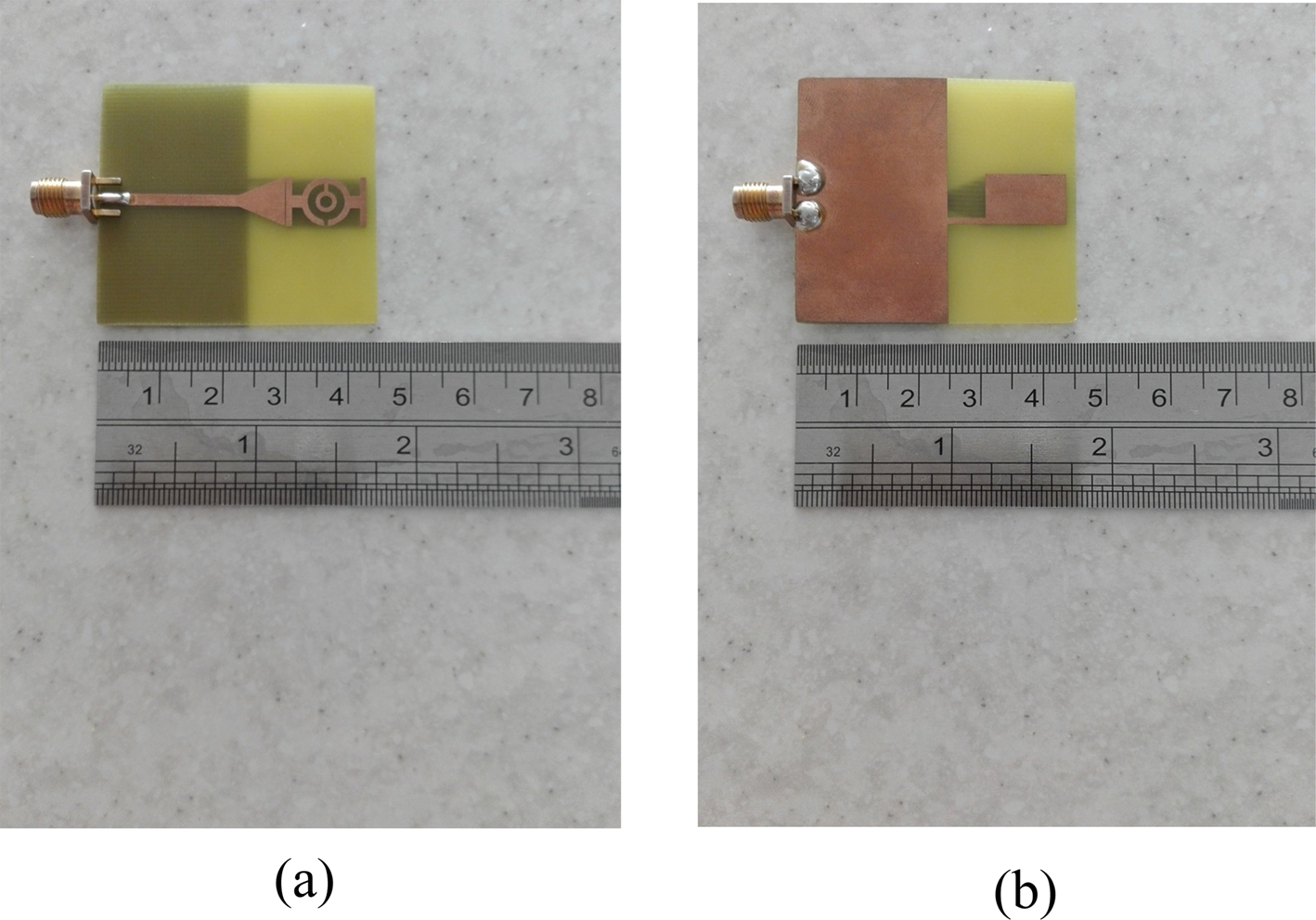
Fig. 7. Fabricated antenna in Fig. 3 with a soldered SMA connector; (a) top view and (b) bottom view.

Fig. 8. Measured and simulated reflection coefficients of the proposed antenna in Fig. 3.
Moreover, a comparison between measured and simulated maximum gain of the proposed antenna is shown in Fig. 9. The measured gain values are about 1.7, 2.45, and 1.75 dB at 2.15, 4.26, and 5.28 GHz, respectively. It is noted that these frequencies represent |S11| measurement resonances in Fig. 8.
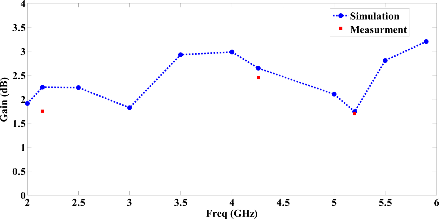
Fig. 9. Measured and simulated maximum gain of the proposed antenna.
Variation of simulated and measured normalized far-field radiation patterns in yz-plane (H-plane) and xz-plane (E-plane) considering 2.15, 4.26, and 5.28 GHz is demonstrated in Fig. 10. As expected, the proposed antenna exhibits a dipolar pattern at E-plane and near omnidirectional pattern at the corresponding H-plane.
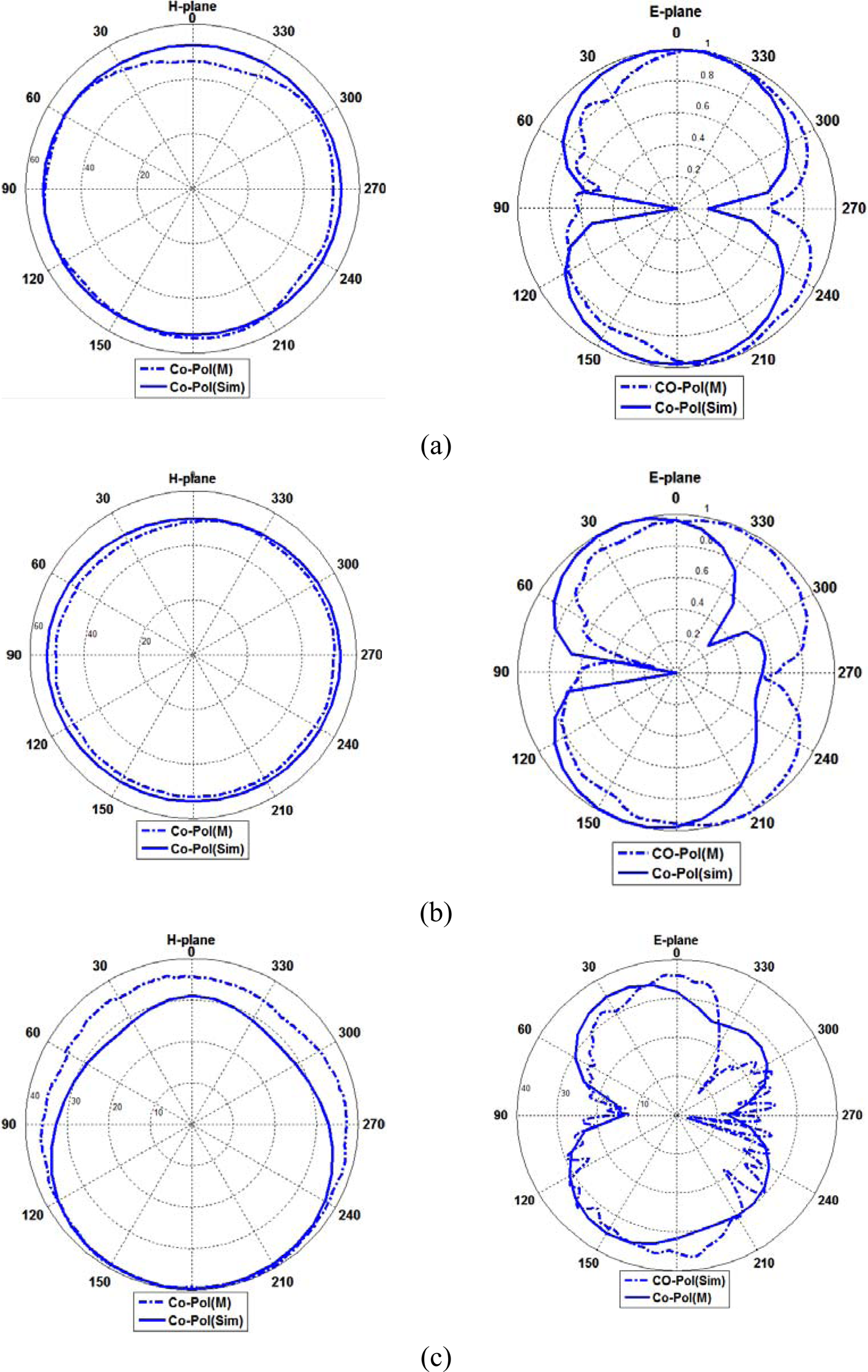
Fig. 10. Radiation patterns of the proposed antenna in Fig. 3 at E- and H-planes considering (a) 2.15 GHz, (b) 4.26 GHz, and (c) 5.28 GHz.
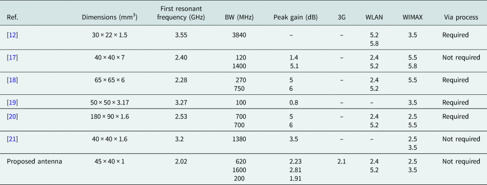
Table 3 summarizes the proposed antenna parameters compared with various antenna configurations reported in [Reference Antoniades and Eleftheriades12, Reference Kim and Park17–Reference Varamini, Keshtkar, Daryasafar and Naser-Moghadasi21]. The provided investigation confirms the efficiency of the designed antenna structure. Utilizing the MTM in the proposed antenna reduces the first resonant frequency and improves corresponding bandwidth. Moreover, a reasonable gain and low profile structure are achieved as well as via-less property of the proposed antenna results in easy and low-cost fabrication.
Table 3. A comparison between the proposed antenna and previously reported similar works
Conclusion
A tri-band compact monopole antenna is proposed for 3G, WiMAX, and WLAN applications. The antenna consists of a small monopole antenna loaded with a single via-free CRLH TL unit cell. Additionally, the antenna exhibits a measured 10 dB return-loss bandwidth at 2.02–2.62, 3.48–4.56, and 5.12–5.34 GHz. The main features of the proposed antenna are achieved compactness, low profile property, via-less structure, and easy integration with other microwave circuits. A 32% antenna geometry compactness is achieved in comparison to the corresponding unloaded monopole antenna. The simulation and measurement results have been investigated to evaluate the performance of the introduced antenna. Moreover, the corresponding equivalent circuit has been extracted. The validity of the proposed equivalent circuit model is investigated using a comparison with corresponding simulation results.
 Mohammadsadegh Kasmaei received his B.S. degree in electrical engineering from the University of Birjand, Birjand, Iran, in 2015, and his M.S. degree in telecommunications from the Shiraz University of Technology, Shiraz, Iran, in 2017. His current research interests include antenna design and metamaterials.
 Ehsan Zareian-Jahromi received his B.S. and M.S. degrees in electrical engineering from the University of Tehran, Tehran, Iran, in 2005 and 2008, respectively, and his Ph.D. degree in telecommunications from the Amirkabir University of Technology, Tehran, Iran, in 2013. From July to December 2012, he was a Visiting Scientist at the University of Bologna, Bologna, Italy. He is currently an Assistant Professor of electrical engineering with the Shiraz University of Technology, Shiraz, Iran. His current research interests include antenna design, metamaterials, periodic structures, electromagnetic compatibility, and numerical methods in electromagnetics.
 Raheleh Basiri received her B.S., M.S., and Ph.D. degrees in communication engineering from Shiraz University, Shiraz, Iran, in 2005, 2008, and 2015, respectively. Since 2015 she has been with the Electrical Engineering Department, Shiraz University of Technology, where she is now an assistant Professor. Her research interests include numerical methods in electromagnetic theory, microwave and terahertz devices and antenna, and graphene and metamaterials.
 Valiollah Mashayekhi was born in Tehran, Iran, in 1983. He received his B.S. degree in electrical engineering from the Shahrood University of Technology, Shahrood, Iran, in 2006, and the M.S. and Ph.D. degrees in telecommunications from the Amirkabir University of Technology, Tehran, Iran, in 2010 and 2017, respectively. He is currently an Assistant Professor of electrical engineering with the Shahrood University of Technology, Shahrood, Iran. His current research interests include antenna design, metamaterials, numerical methods in electromagnetics, electromagnetic compatibility, and power system transients with particular reference to LEMP interaction with electrical networks and grounding systems.