Introduction
Metamaterials, such as frequency-selective surface (FSS), metasurface, left-handed materials, and electromagnetic band gap structures are broadly defined as inhomogeneous or inartificially homogeneous electromagnetic structures for unique properties [Reference Holloway, Kuester, Gordon, O'Hara, Booth and Smith1, Reference Holloway, Love, Kuester, Gordon and Hill2]. Recently, enhancements in bandwidth and an overall reduction in size have been improved by utilizing metamaterials. To realize compact structures, the reactive impedance surface and artificial magnetic conductor (AMC) were introduced to design several wideband circularly polarized (CP) antennas by Agarwal et al., in [Reference Agarwal, Nasimuddin and Alphones3]. Fed by a microstrip feedline through a slot cut on the ground plane, a good metamaterial-based low-profile and high-gain mushroom antenna was proposed, but linearly polarized in [Reference Liu, Chen and Qing4]. An artificial ground structure, which was engineered by arranging truncated corner patch cells, was adopted to achieve an AR width of 20.4% with an overall size of 0.78λ 0 × 0.80λ 0 × 0.96λ 0 [Reference Nakamura and Fukusako5]. Coupling by Z-shaped slot through microstrip feedline, a metasurface-based low-profile antenna was designed with CP radiation, but narrow [Reference Lin, Chen and Liu6]. In our previous work, a 4 × 4array mushroom antenna coupled by an L-shaped slot antenna, which was fed by CPW, was designed to achieve wideband CP radiation and performance of high gain. With metamaterials loading and fed by an L-shaped slot source antenna, CP radiation was enhanced significantly and broadside gain was improved to >10 dBic with a low profile of 0.08 λ 0 .
On the other hand, polarization rotation (PR) technology is commonly used to achieve PR of an electromagnetic wave in quasi-optical systems and microwave as an important application [Reference Nguyen, Lanteri, Dauvignac, Pichot and Migliaccio7–Reference Euler, Fusco, Cahill and Dickie9]. Polarization rotating reflective surfaces (PRRSs) have been widely used in the design of the reflector antennas [Reference Nguyen, Lanteri, Dauvignac, Pichot and Migliaccio7, Reference Euler, Fusco, Cahill and Dickie9], which can be constructed simply by combining the polarization reflector and rotator in a single component. By introducing slots etched along the diagonal line and triangular-shaped fingers in the design of a metal patch cell, a novel PRRS fed by monopole with size reduced was reported [Reference Yue, Jiang and Werner10]. The interdigitated capacitor loading PRRS can achieve a 10% PR bandwidth, but have a worse PR property with a lowest AR of 1.9 dB. In [Reference Zhu, Hong, Wu, Tang, Hao and Chen11], a PR bandwidth of 9.1% was obtained by a novel PRRS based on FSS and using SIW technology. However, dual-via AMC-based PRRS was reported and exhibits a low profile of 0.04λ 0 and a larger PR bandwidth of 29.1%.
In this paper, a novel corner-truncated AMC-based PRRS is proposed for circular polarization. This structure exhibits better PR property and wider PR bandwidth than the dual-via PRRS [Reference Yang, Che, Choi and Tam12], resulting in a much better tunability. Fed by monopole antenna, a wideband and 1 dB AR CP radiation is produced with an application of 4 × 4 proposed PRRS cell.
Antenna configuration and novel PRRS design
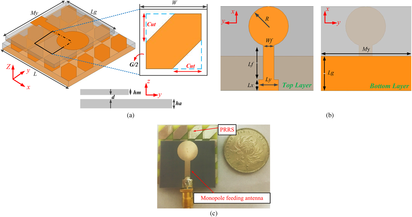
A. Antenna configuration: The configuration of the singly loaded PRRS-based CP antenna is depicted in Fig. 1. The antenna is composed of a PRRS-loaded AMC backed by a metallic sheet and a planar monopole feed. The monopole antenna consists of a partial ground plane and a circular metal patch, which printed on the two sides of a Rogers 3003 substrate (ɛr = 3 and tan δ = 0.0013), respectively. The height of the substrate is 1.5 mm. The AMC-based PRRS is arranged in a 4 × 4 layout with a periodicity W.

Fig. 1. (a) Configuration of the AMC-based PRRS monopole feeding antenna. (b) Top and bottom view of the monopole feeding antenna. (c) Photographs of the fabricated AMC-based PRRS monopole feeding antenna. The dimensions are L g = 9.5, M y = 29, G = 0.3, W = 8, cut = 4, h a = 2.4, d = 0.5, h m = 1.5, R = 5.5, W f = 3, L f = 12.5, L x = 3, L y = 5.5, L = 31.7, all in millimeters.
B. Novel PRRS cell design and analysis: A novel PRRS cell using a newly corner-truncated AMC structure is proposed. The metasurface is a periodic structure with 16 square metal plates arranged in a 4 × 4 layout with a periodicity W. It is shown that the AMC-based PRRS unit cell consists of a square metal patch with a pair of symmetric corner-truncated cut in Fig. 1(a). It is placed on top sides of a dielectric slab of FR4 (ɛr = 4.4, tan δ = 0.02) with a thickness of H = 2.4 mm (0.043λ 0 at 5.4 GHz).
As shown in Fig. 1, the dimensions are listed in detail. In this paper, Ansoft's HFSS was used to analyze the proposed PRRS's reflection properties by adopting the Floquet-port model. Both transverse electric (TE) and transverse magnetic (TM) waves exhibit linearly polarized property, but orthogonal to each other. As depicted in Fig. 2, when a TM-polarized normally incident wave, electric field is along the x-direction, is reflected by the unit cell, both TM- and TE-polarized reflected. As the incident angle is equal to 0°, the TE model of the total broadside radiation is nearly equal in amplitude but 90° phase difference to the TM modes. Then Г TE/TM represents the ratio of an orthogonal TE-reflected electric field to the TM-incident electric field. A TE transmission zeros could be defined that a TE-incident wave mainly converted to an orthogonal TM component. As shown in Figs 3(a) and 3(b), the proposed PRRS has two zeros (f 1 = 5.6 GHz and f 2 = 7.5 GHz). It means that the conversion ratio of the TE-incident wave to an orthogonal TM-reflected wave is nearly 100%, while the phase difference between them is around 90°, thus giving rise to the desired CP radiation. These points could be defined as PR frequency points [Reference Yang, Che, Choi and Tam12]. Then, between the PR points f 1 and f 2, a large PR frequency band could be observed. As shown in Figs 3(a) and 3(b), about 16.8% of the PR bandwidth for |Г TM/TM| < − 10 dB is achieved and a 90° phase difference occurred at 6.2 GHz; it means that a right-hand circular polarization (RHCP) wave can be readily generated, since TM-incident wave lags 90° behind the TE-reflected wave.
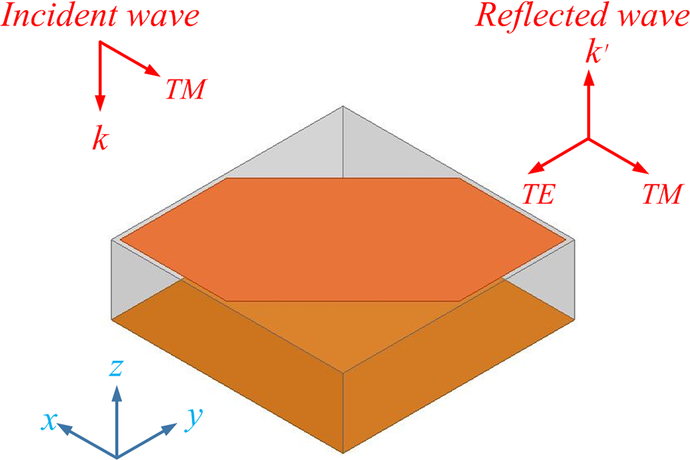
Fig. 2. (a) HFSS model for simulating the response of the unit cell to a normally incident beam containing both a TE- and TM-polarized wave.
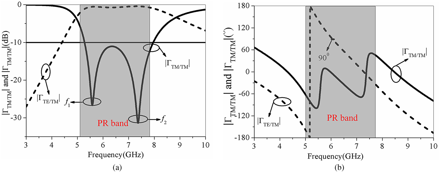
Fig. 3. The reflection coefficients ΓTM/TM and ΓTE/TM of the 2D PRRS for the case of cut = 4 mm: (a) magnitude, and (b) phase.
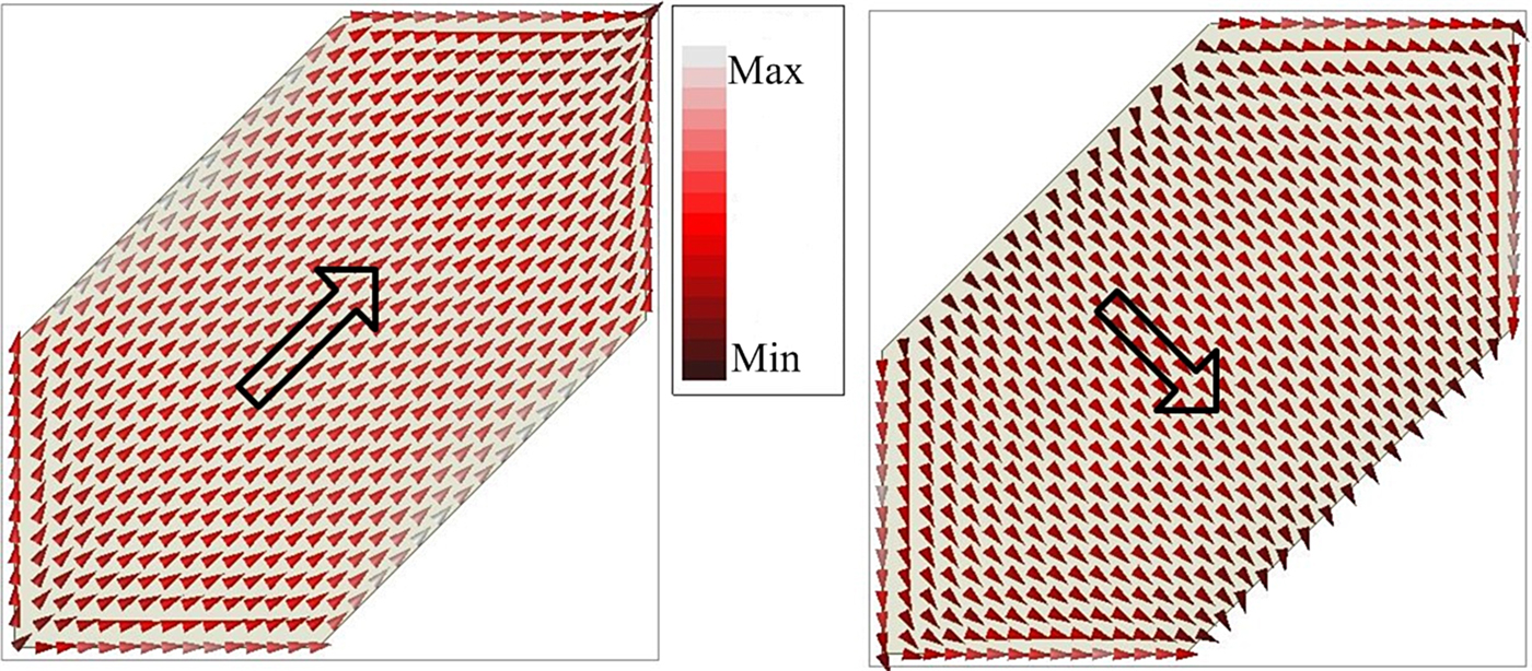
As illustrated in Figs 4(a) and 4(b), the simulated surface current vector distributions of the PRRS cell metal patch at PR frequency points f 1 (5.85 GHz) and f 2 (7.45 GHz), respectively, are all pointing to the diagonal direction in the angle with x-axis at 45°, where symmetric PR properties were validated.

Fig. 4. Surface current vector distribution: (a) at 5.85 GHz, (b) and 7.45 GHz.
In addition, as demonstrated in Fig. 5, the variations cut of truncated corner have great effects on the PR property of the corner-truncated PRRS. Obviously, the PR point f 2 and the magnitude of Γ TE/TM were sensitive to the dimension of cut, but less impact on the PR point f 1 and the 90°-phase point of Г TE/TM. Remarkably, the magnitudes at f 1 and f 2 are all below 30 dB, indicating better PR property than previous reported works. Figure 5(a) shows that, as the cut increases, f 2 tends to shift to higher frequency with impact on PR bandwidth. It could be found that, when the cut is increased to 4.5 mm, a gap will be observed in a large PR band, which divide into two separating PR bands, causing another narrow PR band to shift to high frequency as the cut continues to increase. Then, the cut = 4 mm was selected in this paper to achieve wide PR band. Therefore, the corner-truncated structure can provide wide PR band when total size was adjusted properly. Therefore, a better tunability to achieve wider PR band and better PR property than the dual-via PRRS in [Reference Yang, Che, Choi and Tam12] has been validated. As depicted in Fig. 6, for comparison, magnitudes of both the proposed PRRS and dual-via PRRS [Reference Yang, Che, Choi and Tam12] between ΓTM/TM and ΓTE/TM are given.
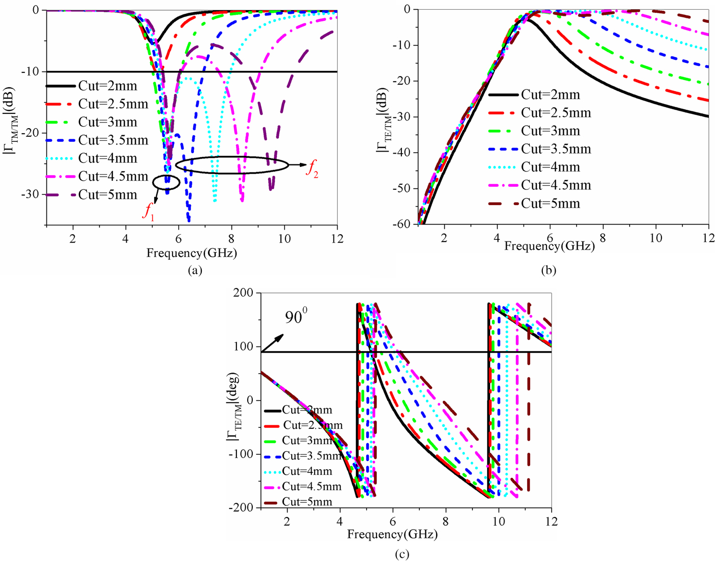
Fig. 5. The reflection coefficients of the 2D PRRS for the cases of different cut increasing from 2 to 5 mm: (a) magnitude of Γ TM/TM, (b) magnitude of Γ TE /TM, and (c) phase of Γ TE/TM.
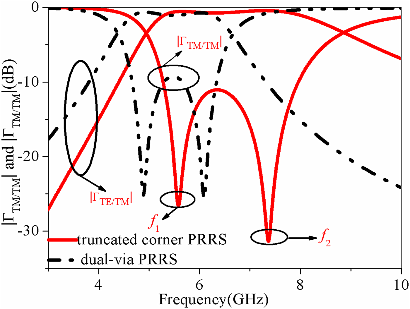
Fig. 6. (a) Magnitudes of reflection coefficients ΓTM/TM and ΓTE/TM of the truncated corner PRRS and dual-via PRRS [Reference Yang, Che, Choi and Tam12].
As shown in Fig. 6, two PR points were observed at the dual-via PRRS and a wide PR band between the two frequency points can be found, but due to a higher magnitude of Г TM/TM, the PR property within the band is worse than that of the proposed corner-truncated PRRS. It can be conclude that the corner-truncated PRRS has better PR property within the PR band and wider PR bandwidth, though two PR points.
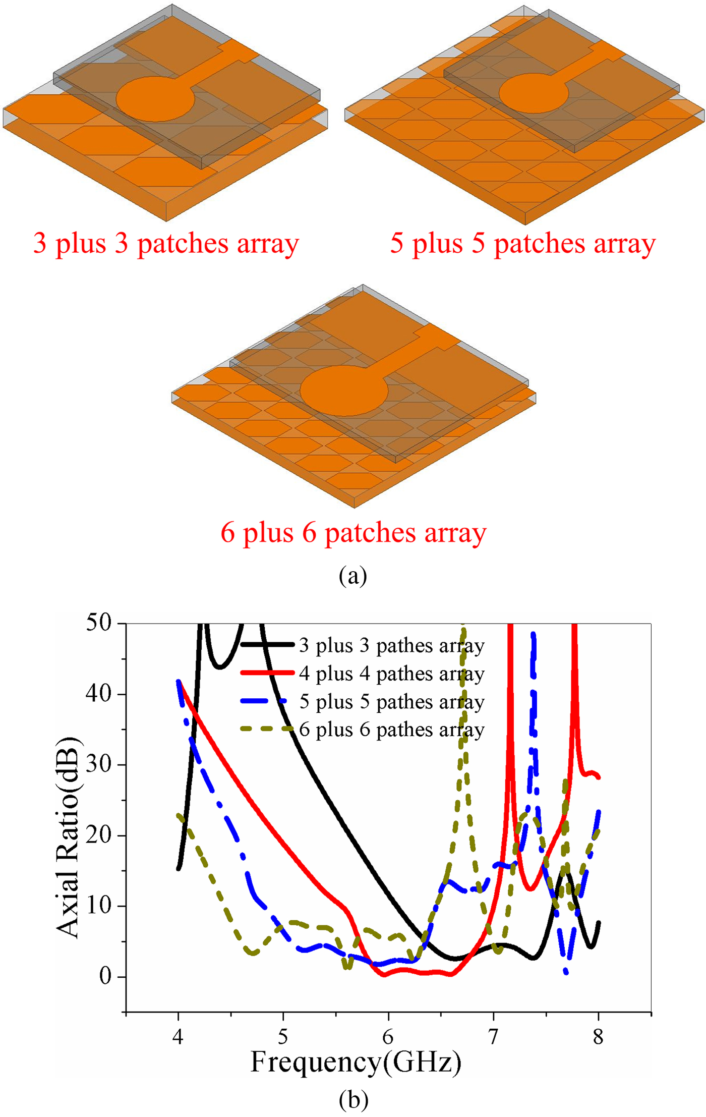
Moreover, as shown in Figs 7(a) and 7(b), for better understanding of the effect of cell configuration on the PR property of AMC-based PRRS, 3 × 3 and 5 × 5 cells layout fed by the same source antenna were simulated and analyzed, it can be found that the AR bandwidth would be enhanced by increasing the number of cells, but the property of circular polarization is much weakened by altering the cells layout. It should be noted that, to our best, the dimensions of source antennas have been simulated numerically to achieve optimum performance for different numbers of cells in PRRS. Obviously, a better PR property of low AR value was exhibited in a 4 × 4 cells layout, and the values of AR were well below 1 dB at most of the CP region. Then, to achieve a better property of circular polarization, a trade-off has to be made when selecting the numbers of cells layout.

Fig. 7. (a) HFSS models of antennas based on PRRS with a different number of patch cells along the x- and y-direction. (b) Simulated AR of the antennas.
Circular polarzation mechanism
To illustrate the mechanism of circular polarization, the simulated surface current vector distributions viewed from the source antenna are shown in Fig. 8. As illustrated in the figures, the simulated surface current vector distributions of the source antenna at 5.76 GHz for four different time phases’ instants, from 0° to 270°, respectively, with an interval of 90°, rotating counter clockwise are depicted, where a RHCP radiation was validated.
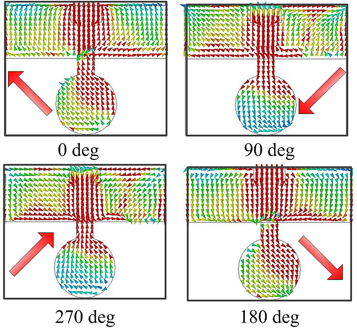
Fig. 8. Surface current vector distribution at 5.76 GHz.
Results of simulatied and measured
As depicted in Fig. 9(a), the AMC-based PRRS monopole antenna has measured a 10 dB bandwidth of 1.8 GHz (5.4–7.2 GHz) and 3 dB axial ratio bandwidth has measured 1 GHz (5.55–6.65 GHz), which is a satisfactory agreement with the simulated results. Its S-parameters were measured using Agilent Vector Network Analyzer (E8361A). The RHCP and left-hand circular polarization radiation patterns and AR were measured in an anechoic chamber using a standard gain horn antenna as a reference and computed using the data from their far-field components and using formulae from the literature [Reference Yang, Che, Choi and Tam13].
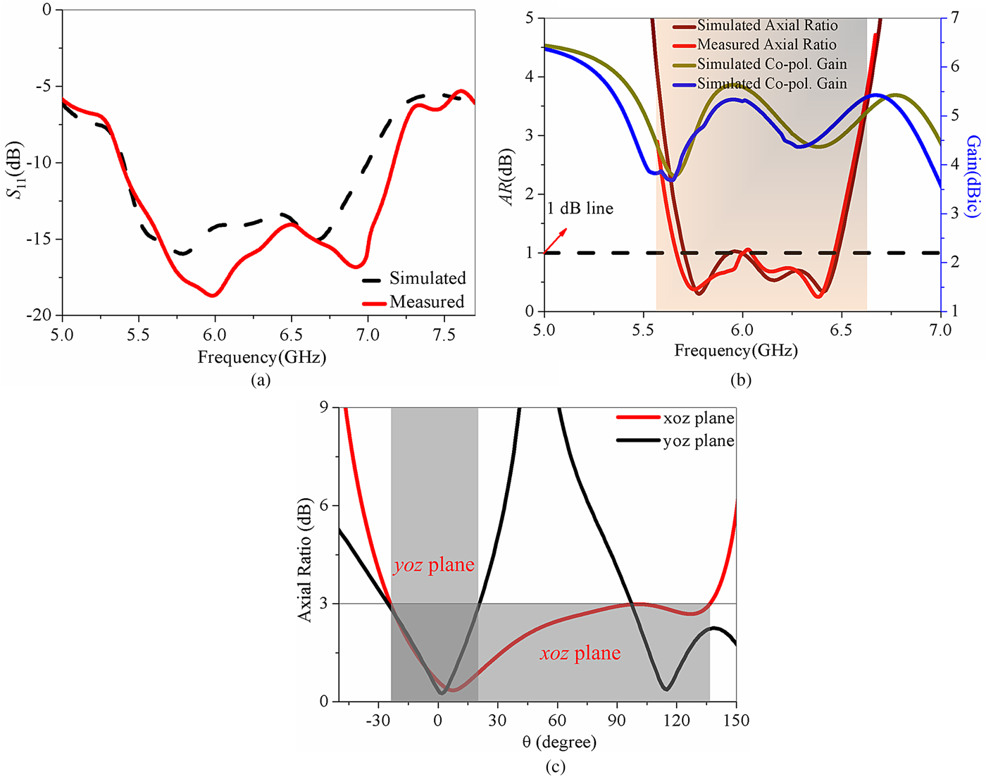
Fig. 9. Simulated and measured results of the proposed antenna (a) |S 11|, (b) RHCP radiation gain and AR, (c) beamwidths of the PRRS-based monopole feeding antenna simulated for AR <3 dB at 6.35 GHz in both the xoz- and the yoz-planes.
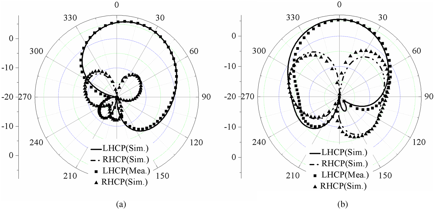
Moreover, as observed in Fig. 9(b), the peak RHCP radiation gain measured along the z-axis within the PR band is 6.1 dBic (achieved at 6 GHz), where a 0.5 dBic degradation to the simulated results. It is demonstrated in Fig. 9(c) that the largest beamwidths, which are achieved at 6.35 GHz, can reach 180° and 75° in the xoz- and yoz-planes, respectively. Moreover, the values of AR can reach below 1 dB at most of the CP band and the lowest AR is 0.23 dB, which exhibits perfect CP properties. As shown in Figs 10(a) and 10(b), the proposed AMC-based PRRS monopole antenna yielded a good broadside RHCP radiation with good cross-polarizations below 25 dB within the bandwidth of CP operation in both the two planes. With good performance and the simple structure, the proposed antenna can be applied on the C (4–8 GHz) bands (Table 1).

Fig. 10. Radiation patterns simulated and measured at 5.4 GHz: (a) in xoz-plane, and (b) in yoz-plane.
Table 1. Performance comparison of the propose antenna and recent single-fed wideband CP patch antennas

Conclusion
In this paper, an AMC-based PRRS monopole feeding antenna is proposed for circular polarization. This corner-truncated AMC-based PRRS cell metal patch has two PR frequency points, wider PR bands, and better PR property than the dual-via PRRS in [Reference Lin, Chen and Liu6]. Fed by monopole antenna, a wideband and 1 dB AR CP radiation is obtained by adopting the arrays of 4 × 4 PRRS cell, where a measured impedance bandwidth of 1.8 GHz (5.4–7.2 GHz) and the 3 dB axial ratio bandwidth of 1 GHz (5.55–6.65 GHz) could be obtained and validated by the measurements. The proposed antenna yielded a good RHCP with a peak broadside gain of 6.1 dBic. Moreover, a lager beamwidth was exhibited at 180° and 75° at xoz- and yox-planes, respectively, within the PR operational bandwidth.
 Qiang Chen was born in Jiangxi, China. He received the bachelor and master degrees from the Air Force Engineering University (AFEU), Xi'an, China, in 2011 and 2013, respectively. He is currently pursuing the Ph.D. degree in Electrical Science and Technology, AFEU. His research interests include microwave circuits, antennas, and arrays. E-mail address: cqky1989@126.com.
 Hou Zhang received his B.S., M.S., and Ph.D. degrees all in Electromagnetic Field and Microwave Technology from the Xi'an Electronic and Engineering University, Xi'an, China; Air Force Missile College, Xi'an, China; and Xidian University, respectively. Dr. Zhang has been the session Chairs of PIERS and APEMC. He is currently interested in planar antennas and EMC. Prof. Zhang has published over 150 technical papers and authored/edited six books. He is holding six granted/filed patents. E-mail address: warmer88@163.com
 Lu-Chun YANG was born in Jiangxi, China, in 1990. She received the B.S. degree from the Xi'an University of Posts and Telecommunications, Xi'an, China, in 2012, and the M.S. degree from the Southeastern University, Nanjing, China, in 2015, respectively. Her research interests include telecommunication engineering and integrated circuit design. Now she works for China Mobile (Shenzhen) Limited as a Software Engineer. E-mail address: 1063383077@qq.com
 Xiao-Fei Zhang received the B.S. degree in the Air Force Engineering University, Xi'an, China, in 2013. He is now pursuing the Ph.D. degree in the National Defence Key Laboratory of the Air Force Engineering University. His current research interests include automobile radars, beam steering antennas, millimeter-wave antennas and arrays, electrically small antennas, antenna characteristic modes, reconfigurable antennas, and metamaterial antennas. E-mail address: zxf1990fei@163.com
 Yi-Chao Zeng was born in Sichuan, China, in 1994. He is now pursuing the B.S. degree in the Air Force Engineering University, Xi'an, China. His current research interests include microwave circuits, antennas, and arrays. E-mail address: 18729874867@163.com