INTRODUCTION
Radiation therapy is a treatment of choice for the treatment of superficial malignancies such as cutaneous lymphoma, melanoma, angiosarcoma, mycosis fungoides, Kaposi’s sarcoma, sebaceous carcinoma, basal and squamous cell carcinoma, that may extend into the entire scalp region and forehead. In these patients, irradiation of the total scalp may be necessary to treat these superficial tumours, particularly when surgical excision is not possible or is not the treatment of the choice.Reference Tung, Shiu, Starkschall, Morrison and Hogstrom 1 The goal of total scalp irradiation is to deliver a uniform dose throughout the target area while minimising dose to the brain and optical structures. This requires measuring the dosimetry of the electron fields before the radiotherapy session, due to the convex surface of the calvarium and the close proximity of the scalp to the adjacent normal brain tissue. In addition, fields must encompass any multifocal spread of the lesion. In this situation, dose delivery is technically challenging and therefore the goal of scalp uniform irradiation is difficult to achieve. In this regard, various irradiation techniques concerning the treatment of scalp malignancies have been suggested in the medical literature. These include a lateral electron–photon technique, a helmet-shaped mould incorporating the use of high dose-rate (HDR) brachytherapy,Reference Liebmann, Pohlmann, Heinicke and Hildebrandt 2 a linear accelerator based intensity-modulated radiation therapy and helical tomotherapy.Reference Able, Mills, McNeese and Hogstrom 3 Another study verified three different modalities include helical tomotherapy, lateral photon–electron (LPE) therapy and volumetric-modulated arch therapy showed there is best conformity for helical tomotherapy and the LPE plan showed the worst, despite the similar homogeneity indexes.Reference Song, Jung and Park 4
The traditional electron beam technique can deliver a relatively high dose to the scalp and a relatively low dose to the underlying brain tissues. Nevertheless, electron beams may cause labour intensive treatment set up with numerous electron beam junctions.Reference Mellenberg and Schoeppel 5 , Reference Walker, Wadd and Lucraft 6 In the conventional combined electron–photon modality technique, an adequate target volume dose can be accomplished, with improved dose uniformity by virtue of overlapped fields whilst sparing dose to the normal brain tissues and eyes. This makes the treatment set up less tedious and less time consuming but incidence of beam angle and field matching remain a problem.Reference Akazawa 7 , Reference Orton, Jaradat, Welsh and Tomé 8 Photon intensity-modulated radiotherapy (IMRT) is an effective and feasible approach to treat extensive scalp malignancies.Reference Chan, Song, Burman, Chui and Schupak 9 Non-coplanar beams could increase dose homogeneity and planning target volume coverage and might reduce dose particularly to the optic chiasm.Reference Ostheimer, Janich, Hübsch, Gerlach and Vordermark 10 Electron beam treatment for scalp tumours can be an easy and effective treatment for palliative intent in elderly patients with squamous cell carcinoma, because good results can be achieved even without considering the dose at field junctions.Reference Caivano, Fiorentino, Pedicini, Califano and Fusco 11
The use of HDR brachytherapy can achieve the most conformal treatment and treatment delivery is well tolerated which is delivered in less treatment sessions in contrast to external radiotherapy.Reference Wojcicka, Lasher, McAfee and Fortier 12 This technique could be clinically convenient for treatments requiring a lower prescription dose and for patients who cannot lie on the treatment couch.Reference Wojcicka, Lasher, McAfee and Fortier 12 However, due to the dose fall-off characteristics of 192Ir source, the HDR modality produces a 58–242% dose gradient within the target volume. Moreover, the underlying brain tissues and optical structures received the highest doses with the HDR brachytherapy technique when compared with IMRT and 3DCRT.Reference Liebmann, Pohlmann, Heinicke and Hildebrandt 2 , Reference Wojcicka, Lasher, McAfee and Fortier 12 The IMRT technique constitutes a promising and possible way to treat extensive scalp lesions and provides superior target coverage of the treatment volume with the most homogenous as well as conformal dose distribution within the target.Reference Chan, Song, Burman, Chui and Schupak 9 The dose to the brain tissue and lens are slightly higher in the IMRT plan, although this is clinically satisfactory. The IMRT is sensitive to set up uncertainty and can involve long treatment times in an uncomfortable position.Reference Orton, Jaradat, Welsh and Tomé 8 . Most recently, helical tomotherapy has shown that it can be used to treat the scalp with tangential beamlets. Despite the concern that the tomotherapy planning system can over estimate the calculated superficial doses for head and neck treatments, this modality eliminates the need for bolus as well as avoiding field matching problems and the need to use of more than one modality.Reference Orton, Jaradat, Welsh and Tomé 8 , Reference Hardcastle, Soisson, Metcalfe, Rosenfeld and Tomé 13
Although electron beams have multiple issues during treatment delivery such as lateral scattering, they have a sharp fall-off of dose and good coverage for skin tumours. Symmetry and flatness of an electron beam depend on beam flattening system design and equipments are used for beam collimation. Electron field uniformity would be defined by the specific set-up which is recommended by the IAEA TRS-398 and AAPM TG-51 protocols in a specified area of the beam at determined depth.Reference Niroomand‐Rad, Blackwell and Coursey 14 , Reference Andreo, Burns and Hohlfeld 15 The reference depth used for this determination has traditionally been at or close to the depth of maximum dose.Reference Khan and Gibbons 16
Uniformity across the electron field, which is compulsory for quality assurance, is another statement of symmetry and flatness. It determines dose variation over 80% in a plane, parallel to the surface of the phantom and perpendicular to the central axis in a standard field size at 10-cm depth. This variation in every point of measurement in 10 cm depth is accepted around 3% of measurement in central axis.
We can calculate flatness and symmetry from the following Equation (1)Reference Pathak, Mishra, Singh and Mishra 17 :
 $$\hskip-10pt\eqalignno{ & {\rm Flatness}\,\left(% \right){\equals}D_{{{\rm max}}}/D_{{{\rm min}}} {\times}{\rm 1}00 \% \cr & {\rm Symmetry}\,\left(% \right){\equals}\cr & \quad{{\left[ {D\left( {{\rm x},\,{\rm y}} \right)} \right]} \mathord{\left/ {\vphantom {{\left[ {D\left( {{\rm x},\,{\rm y}} \right)} \right]} {\left[ {D\left( {{\minus}\!{\rm x},{\minus}\!{\rm y}} \right)} \right]}}} \right. \kern-\nulldelimiterspace} {\left[ {D\left( {{\minus}{\rm x},\,{\minus}{\rm y}} \right)} \right]}}{\times}{\rm 1}00 %\,.$$
The purpose of this study was to assess the dosimetry of electron beams when they are applied to scalp in contrast to 3DCRT (photon modality). This was clinically useful because we currently have no IMRT in our centre, and also beneficial to providing a new approach for analysing dose distribution and informing the best way to treat successfully scalp malignancy.
In this study, we measured the beam profile and percentage depth dose (PDD) using GAFCHROMIC® EBT2 films (International Specialty Products, Wayne, NJ, USA) for 6 MeV variation measurements by using abutting non-coplanar electron fields, measured in skin and the influences of bone heterogeneity challenged by, utilising an anthropomorphic phantom (RANDO, Alderson Radiation Therapy phantom).
METHOD AND MATERIAL
Calibration and verification
This study analysed Gafchromic® EBT2 films employed for dosimetry goals, which have a low sensitivity to light, independence to energy 100 keV–6 MV. Handling of film was based on the recommendations of the AAPM TG55 report,Reference Niroomand‐Rad, Blackwell and Coursey 14 these films include a yellow dye marker that is known to active a layer that has less sensibility to light. Films were analysed by using a colour scanner which is designed to scan colour films in the red, green and blue bands of the visible spectrum. Once a red, green and blue (RGB) scan has been obtained, the user can extract the information from the red colour channel where the active component in EBT2 film produces its maximum response through the RGB mode (in red channel) because the wavelength of scanner is about 632 nm that is well matched to the maximum spectral in EBT2 film. Also for preventing Newton rings occurring, flat board Microtek 9800XL (Microtek lab Inc., Moraine, OH, USA) scanner was utilised. The scanner systems have the advantage of shortening the time to read the film.
Nominally changes between the two sides of film, top and right of each film, lead to create a small cutting or marking the film, based on the company recommendation to achieve a uniform response in scan, during the scan of film.Reference Lynch, Kozelka, Ranade, Li, Simon and Dempsey 18
During work with gafchromic films care has to be taken to avoid fingerprints and dust.
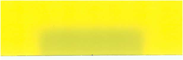
To make a calibration curve, 33 pieces of film were prepared in size of 1·5×2·0 cm2 (Figure 1) 24 hours before exposure. Based on ISP protocolsReference Xu 19 scanning process (by Mikroteck scanner) should be done 24 hours after irradiation. Scan of films (tiff image) were analysed with Image J software produced by America’s Health Research Centre.Reference Mayers 20 , Reference Sim, Wong and Ng 21
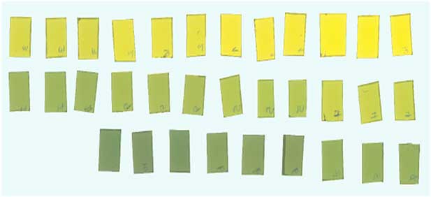
Figure 1 EBT2 films for calibration.
In order to determine beam profile and PDD, radiation was measured in a slab phantom, at central axis and with a 10×10 cm electron applicator. All results were normalised to 100.
A Varian Clinac 2100C (Varian Medical Industry Palo Alto, CA, USA) as linear accelerator machine was utilised in Imam Khomeini Hospital. The accelerator is capable of generating electron energies in the range of 6, 9, 12, 18 and 20 MeV and photon energies 6 and 18 MV.
The calibration curve was plotted based on the optical density [Equation (2)] and certain step doses were irradiated onto the films (dose steps: 0, 0·5, 1, 2, 3, 5 Gy) (Figure 1).
Other data, including PDD and profile curve dose were attained and then were compared with the calibrated films (Figure 2) and plane parallel chamber (Figure 3).
 $$\eqalignno{ & {\rm netOD}{\equals} OD_{{{\rm exp}}} {\minus}OD_{{{\rm unexp}}} \cr & {\rm netOD}{\equals} {\rm log}_{{{\rm 10}}} {{I_{{{\rm unexp}}} {\minus}I_{{{\rm exp}}} } \over {I_{{{\rm exp}}} {\minus}I_{{{\rm backg}}} }}. $$

Figure 2 Film for profile and percentage depth dose.

Figure 3 Set up of film to achieve profile and percentage depth dose (energy 6 MeV, Varian Linac accelerator, SSD=100 cm, FSD=10×10 cm).
Film features include a wide-dose range (0–8 Gy), energy independence, low sensitivity to natural light and high uniformity. 22 These features encouraged us to use Gafchromic® EBT2 films.
Another step was taken to make PDD and profile curves of the 6 MeV electron field using measurements by analysing the pieces of film after irradiation.
A plane parallel chamber was utilised as a reference dosimeter. This type of dosimeter should be used for beam qualities R 50<4 g/cm2) (E 0_10 MeV). The reference point for plane parallel chambers is taken to be on the inner surface of the entrance window, at the centre of the window.Reference Andreo, Huq and Westermark 23 Dosimetry was measured at the point of interest (0·5, 1·4, 2·4 cm) in the water phantom. Well-guarded plane parallel ionisation chambers are designed to minimise the scattering perturbation effect. In addition to this the effective point of measurement is the inner surface of entrance window, at the centre of the window.Reference Andreo, Huq and Westermark 23
Phantom irradiation
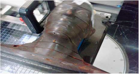
For simulating treatment set up an Alderson Rando phantom (Machlett, Springdale, CA, USA) was utilised, which is tissue equivalent to the human scalp (Figures 3 and 4). Five fields without any gaps between junctions was drawn onto the phantom to cover the whole of the scalp. To avoid field overlap or a gap, every field was modified by gantry, couch angle and shielding. In the temporal lobe region, two lateral fields with a gantry degree 90–270° were used. In the occipital region, a prone position was selected for the phantom with non-coplanar technique (couch 90°). By reducing the number of fields selected, both set up errors and hot or cold spots during transformations was reduced. Points of interests were field’s match lines and curvature of scalp.
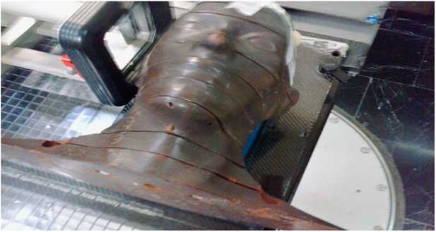
Figure 4 Set up of Rando phantom.
RESULTS
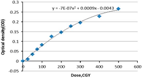
The calibration curve in EBT2 gafchromic films was plotted with two data; dose and optical density. The latter is measured after scanning the irradiated film. Measurements were extracted from the irradiation of 33 piece of films three times to provide a correct statistical measurement [Equation (2)] and at certain doses displayed in Figure Reference Mellenberg and Schoeppel5. Different steps of dose to films produce different optical densities ranged between (0 and 0·3), background irradiation was calculated using non-irradiated films. In order to have a proper utilisation of the calibration curve, data assessed by EXCLE and the following Equation (3) was applied
 $$\eqalignno{ &(D{\rm (cGy){\equals}}\cr & {642} \cdot {\rm 857}{\minus}\left( {714,286\sqrt {{\rm 0} \cdot {\rm 0000007988}{\minus}0 \cdot {\rm 0000028}{\times}OD} } \right).$$

Figure 5 Calibration curve (SSD=100 cm, field size=10×10 cm gantry rotation=0).
There was an acceptable range between data extracted from films and the chamber. This ensures films are reliable for use in dosimetry. In other words, we can use such films for absolute dosimetry with repetition of film measurements.
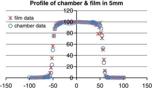
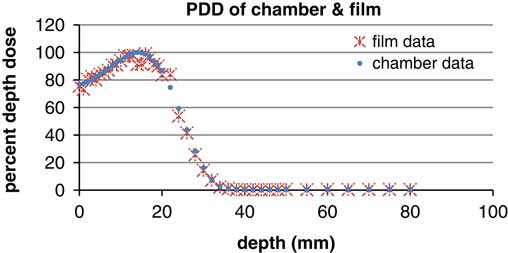
According to the graphsReference Walker, Wadd and Lucraft 6 – Reference Orton, Jaradat, Welsh and Tomé 8 there are acceptable results between film EBT2 and the plane parallel chamber. In the three depths of measurement there was a negligible difference of about 2%. Conformity and symmetry of Gafchromic® EBT2 had been approved before selecting them for dosimetry in the phantom (Figure 6).

Figure 6 Profile of parallel plane chamber and gafchromic EBT2 (energy: 6 MeV, depth: 5 mm, field size: 10×10 cm).
In the second part of this study, we measured the beam dosimetry using five different fields without using bolus on the phantom, this produced a dose range of 78–97% of maximum dose. There is a prediction of surface phantom dose by using 6 MeV energy. In other words, gafchromic films on the slab phantom had been tested before using anthropomorphic phantom which has shown the surface dose on slab was 50 cGy. So we predicted the surface dose will be in a range of 50 cGy with the time of 100 MU. In the occipital region, because of topographic shape of phantom and type of irradiation the dose was ~78 cGy. Field borders needed shielding to prevent overlap of dose and we found border doses varied sharply (Table 1) and calculated doses were between 74 and 97 cGy, this demonstrates that electron beams produce hotspots and lateral scattering in the field borders (Figures 7 and 8).
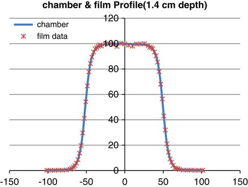
Figure 7 Profile of parallel plane chamber and gafchromic EBT2 (energy: 6 MeV, depth: 14 mm, field size: 10×10 cm).

Figure 8 Percentage depth dose (PDD) of parallel plane chamber and gafchromic EBT2 (energy: 6 MeV, field size: 10×10 cm).
Table 1 Dose variation and pixel values (PV) and optical density (OD) in a part of film in the border
In the frontal lobe field, variation of dose is constant and monotonous nearly; the range of variation was around ±6% but in the junctions; there was a conspicuous range of 74–97 cGy.
DISCUSSION
In the treatment of the scalp region using electron beams, scalp curvatures lead to an air space between the applicator and the surface of skin, which produces electron lateral scattering, and subsequently we observe a decline in D max around the treatment field. Another prominent factor that should be considered is the oblique factor which is important when the radiation angle is more than 60°. In this situation, there is a space between the applicator and phantom. It means dose would be increased by increasing the perpendicular line between the applicator and scalp. One point to be highlighted is the scalp tissue heterogeneity which influences the electron dose in the scalp surface.
Heterogeneity of tissue, especially with low density, causes the absence of electron equilibrium which impacts on the dosimetry. In this case, the selection of gafchromic film is a good choice because of its high spatial resolution, flexibility in recording dose and is user friendly.
Electron irradiation demonstrated dose distributions depending on field curvatures and air gap between scalp and the applicator. In other studies, such as in the application of six electron fields with a 3 mm gap between each field, results displayed a variation of ~50–70% despite shifting the fields in the middle of the given total dose.Reference Able, Mills, McNeese and Hogstrom 3 In our technique, dose between field gaps was modified by using 3 mm gaps in the sagittal plane and removing gaps in the coronal plane. Results indicate a 10–50% variation [Equation (1)].
In other techniques, such as using electron and photon beams with or without overlapping there was 80–110 and 85–103% variation in dose in the borders respectively.Reference Song, Jung and Park 4 All techniques mentioned above utilised 6 mm of bolus.
In our study, the dose variation in field junctions when there are no gaps between fields was 74–97% (Table 1). Our methods have the enormous privilege of saving time and reducing errors due to the removal of gaps between treatment fields. In the treatment of scalp lesions, the brain is considered to be an organ at risk (with a maximum tolerance of a TD 55 Gy). A scalp tumour such as a basal cell carcinoma, which requires a treatment dose of 60 Gy, make a demand on a modified technique to decrease the brain dose. In electron beam technique, in order to achieve a rapid fall-off dose to reduce the complication of over irradiating brain tissue and achieve a good coverage of the tumour, requires careful beam positioning. This requires precise dosimetry and planning with good immobilisation. Therefore, electron treatment in scalp malignancy needs further studies.
CONCLUSION
Dose uniformity throughout the fields demonstrates scalp treatment using electron beams is a good method for treating cancer. However, hotspots arising in the field borders indicate that electrons display complicated dosimetric behaviour and requires accurate dosimetry before treatment, this can be achieved by using Gafchromic® EBT2 films. In conclusion, electron beams are a good modality for treating one flat field, in the special topography of scalp, whole scalp treatment requires a precise field matching and dosimetry.
Acknowledgements
The authors thank the fellow doctoral students for their feedback, cooperation and of course friendship. In addition, the authors express their gratitude to the staff of Cancer Institute of Imam Khomeini Hospital for the last minute favours.