1. INTRODUCTION
High energy density physics (HEDP) aims to study the properties of matter under extreme states of high temperature and high pressure. This is quite important for the inertial confinement fusion research, astrophysics, as well as plasma physics study. Intense laser and particle beams have been used to produce high energy density (HED) matter in laboratory for years (Beg et al., Reference Beg, Stephens, Xu, Haas, Eddinger, Tynan, Shipton, Debono and Wagshal2006; Atzeni et al., Reference Atzeni and Meyer-Ter-vehn2004; Hora et al., Reference Hora, Malekynia, Ghoranneviss, Miley and He2008; Tahir et al., Reference Tahir, Stöhlker, Shutov, Lomonosov, Fortov, French, Nettelmann, Redmer, Piriz, Deutsch, Zhao, Zhang, Xu, Xiao and Zhan2010; Dewald et al., Reference Dewald, Milovich, Michel, Landen, Kline, Glenn, Jones, Kalantar, Pak, Robey, Kyrala, Divol, Benedetti, Holder, Widmann, Moore, Schneider, Döppner, Tommasini, Bradley, Bell, Ehrlich, Thomas, Shaw, Widmayer, Callahan, Meezan, Town, Hamza, Dzenitis, Nikroo, Moreno, Van Wonterghem, Mackinnon, Glenzer, Macgowan, Kilkenny, Edwards, Atherton and Moses2013; Rygg et al., Reference Rygg, Jones, Field, Barrios, Benedetti, Collins, Eder, Edwards, Kline, Kroll, Landen, Ma, Pak, Peterson, Raman, Town and Bradley2014) In general, HED matter can only be transiently produced in laboratory on a time scale of nanoseconds (ns). The pressure in a HED sample could exceed 1 Mbar (100 GPa), and the expansion velocity would be in the range of km/s. Therefore, diagnostic techniques with temporal resolution better than ns and spatial resolution better than 10 µm are necessary. Typically, a low Z (atomic number) material could be compressed by high Z materials from mm to 100 µm in size and from 10−2 to 102 g/cm3 in density, so the imaging system must work for a quite wide dynamic range. Besides, the imaging system must be sensitive to a mixture of high Z and low Z elements as well, because it is essential to measure the moving boundary and the proportions of different materials in order to understand the hydrodynamic processes of the HED sample. What is more, to get the full image of the compression from the 4п solid angle, a time dependent imaging system in the three orthogonal directions is desirable.
Many ultrafast imaging diagnostic tools are based on the use of hard X-rays, Gama rays, electron, proton, and carbon beams or even neutron beams produced by high power laser or other pulsed power like pinch device (Edwards et al., Reference Edwards, Sinclair, Goldsack, Krushelnick, Beg, Clark, Dangor, Najmudin, Tatarakis, Walton, Zepf, Ledingham, Spencer, Norreys, Clarke, Kodama, Toyama and Tampo2002; Beg et al., Reference Beg, Krushelnick, Lichtsteiner, Meakins, Kennedy, Kajumba, Burt and Dangor2003; Li et al., Reference Li, Séguin, Rygg, Frenje, Manuel, Petrasso, Betti, Delettrez, Knauer, Marshall, Meyerhofer, Shvarts, Smalyuk, Stoeckl, Landen, Town, Back and Kilkenny2008, Reference Li, Séguin, Rygg, Frenje, Manuel, Petrasso, Betti, Delettrez, Knauer, Marshall, Meyerhofer, Shvarts, Smalyuk, Stoeckl, Landen, Town, Back and Kilkenny2010; Roth et al., Reference Roth, Jung, Falk, Guler, Deppert, Devlin, Favalli, Fernandez, Gautier, Geissel, Haight, Hamilton, Hegelich, Johnson, Merrill, Schaumann, Schoenberg, Schollmeier, Shimada, Taddeucci, Tybo, Wagner, Wender, Wilde and Wurden2013; Sheng et al., Reference Sheng, Zhao, Yang, Wei, Jiang, Zhou, Cheng, Yan, Li, Yang, Yuan, Xia and Xiao2014; Zhao et al., Reference Zhao, Cheng, Wang, Zhou, Lei, Sun, Xu, Ren, Sheng, Zhang and Xiao2014, Reference Zhao, Cao, Cheng, Shen, Zhang, Zhao, Gai and Du2015). High energy proton radiography developed at Los Alamos National Laboratory (LANL) has shown its great potential for HED matter diagnostics with excellent spatial and temporal resolution (King et al., Reference King, Ables, Adams, Alrick, Amann, Balzar, Barnes, Crow, Cushing, Eddleman, Fife, Flores, Fujino, Gallegos, Gray, Hartouni, Hogan, Holmes, Jaramillo, Knudsson, London, Lopez, Mcdonald, Mcclelland, Merrill, Morley, Morris, Naivar, Parker, Park, Pazuchanics, Pillai, Riedel, Sarracino, Shelley, Stacy, Takala, Thompson, Tucker, Yates, Ziock and Zumbro1999; Merrill et al., Reference Merrill, Campos, Espinoza, Hogan, Hollander, Lopez, Mariam, Morley, Morris, Murray, Saunders, Schwartz and Thompson2011; Merrill, Reference Merrill2015). This technique is also proposed at the Facility for Antiproton and Ion Research (FAIR) with 4.5 GeV proton beams (Merrill et al., Reference Merrill, Golubev, Mariam, Turtikov and Varentsov2009; Varentsov et al., Reference Varentsov, Bogdanov, Demidov, Golubev, Kantsyrev, Lang, Nikolaev, Markov, Natale, Shestov, Simoniello, Smirnov and Durante2013). Although proton beam is superior to electron beam in the aspect of penetration ability, a high energy proton accelerator and the corresponding imaging system is really costly, and a ps-scale proton beam bunch with desirable energy and intensity for radiography is not yet available in the laboratory. Besides, proton radiography facility is always much larger in size than electron radiography system.
The principle of electron radiography is similar to that of the high energy proton radiography, a resolution of ~100 µm for a static sample has been demonstrated with 30 MeV electron beam at LANL (Merrill et al., Reference Merrill, Harmon, Hunt, Mariam, Morley, Morris, Saunders and Schwartz2007). Obviously, such a resolution is not enough for HEDP experiments, let alone that the temporal resolution was not taken into account. To fit well with the requirements for HEDP or inertial confinement fusion (ICF) studies, here we propose a practical method that uses a relatively high energy (100 MeV-GeV) electron bunches as the probe beam in order to get both high temporal and high spatial resolution. Moreover, within this proposal, it is possible to get dynamic images in the three orthogonal directions simultaneously.
2. PROPOSED ELECTRON RADIOGRAPHY SCHEME
The generation of high quality electron beams from accelerators based on radio frequency (RF) photocathode gun was developed 20 years ago by Fraser et al. (Reference Fraser, Sheffield, Gray, Giles, Springer and Loebs.1987). Since then, it became a commonly used technology for accelerator and Free Electron Laser facilities (Power, Reference Power2010). A typical electron Linear Accelerator (e-LINAC) is shown schematically in Figure 1. Beams with bunch intensity ranging from a few pC to 100 nC, and bunch length of 1 ps or even less can be generated at RF of 1–12 GHz. A mode locked laser is used to produce a train of several electron bunches with bunch interval as short as 100 ps. State of the art technology allows the electron beam timing to be locked to a master clock with a timing jitter <1 ps. Normalized emittance from RF guns is typically 1 mm-mR/nC with about 1% energy spread. This fits the proposed scheme for the high spatial resolution requirement in radiographic studies. The beam energy can be increased easily from a few MeV to GeV by adding more accelerating sections without any impact on the other beam parameters. Details can be found in Power (Reference Power2010).

Fig. 1. A typical RF photocathode electron injector system.
With a flexible beam from e-LINAC, one can easily generate a bunch group of three electron beamlets or more separated by one or more RF period. As shown in Figure 2, in order to image a target in the three orthogonal directions, here three beamlets are set in one bunch group. When the beamlets exit the accelerator, they can pass through a 1/3 harmonic deflecting cavity and can be separated to three directions. With a septum magnet and achromatic matching beam lines, the three beamlets are then delivered to the target in three orthogonal directions simultaneously. In addition, a second and third bunch group can be generated at arbitrary time delays and used for a temporal evolution study of the HEDP target with ps accuracy.
Fig. 2. Scheme of the imaging system with an e-LINAC in three orthogonal direction.
The sequence imaging interval can be definitely set in order of 100 ps or even lower with the very high (around 10 GHz) RF accelerator. However, it is not easy to find such a fast imaging screen with reasonable high fluorescence conversion efficiency except a rapid charge coupled device (CCD) camera for recording the sequence of the images. To solve the problem, a new design similar with streak camera is proposed as shown schematically in Figure 3. An RF deflector could be introduced after the magnet imaging system for spatially separating and directing electron beamlets to different transverse positions on the screen. This design makes it possible to dynamically record the density revolution of an imploding HED/ICF target with rate of about 1010 frames/second during one dynamic event.
Fig. 3. System scheme for rapid acquisition of the imaging information, which is similar to a streak camera but recording a 2D image.
Apart from high temporal resolution, high spatial resolution, and wide dynamic responding range are also required for precise imaging of a HED/ICF target. The principle of charged particle radiography with a magnet imaging system has been demonstrated elsewhere (King et al., Reference King, Ables, Adams, Alrick, Amann, Balzar, Barnes, Crow, Cushing, Eddleman, Fife, Flores, Fujino, Gallegos, Gray, Hartouni, Hogan, Holmes, Jaramillo, Knudsson, London, Lopez, Mcdonald, Mcclelland, Merrill, Morley, Morris, Naivar, Parker, Park, Pazuchanics, Pillai, Riedel, Sarracino, Shelley, Stacy, Takala, Thompson, Tucker, Yates, Ziock and Zumbro1999; Merrill et al., Reference Merrill, Harmon, Hunt, Mariam, Morley, Morris, Saunders and Schwartz2007, Reference Merrill, Golubev, Mariam, Turtikov and Varentsov2009, Reference Merrill, Campos, Espinoza, Hogan, Hollander, Lopez, Mariam, Morley, Morris, Murray, Saunders, Schwartz and Thompson2011; Varentsov et al., Reference Varentsov, Bogdanov, Demidov, Golubev, Kantsyrev, Lang, Nikolaev, Markov, Natale, Shestov, Simoniello, Smirnov and Durante2013). In general, by setting a fine-designed point to point magnet imaging system, the spatial resolution is somehow dominated by the second chromatic aberrations and proportional to the chromatic length (L c, which is inversely proportional to the magnification of the lens system, M), the angular spread of the accepted beam (ϕ, which can be reduced to the collimate angle by setting an aperture at the Fourier plane in the beam optics), and the momentum (p) deviation from the central trajectory (∆p/p, which also can be reduced by properly collimating the magnetic imaging system). The formula for the spatial resolution Δx can be written as Eq. (1).
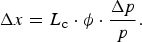 $${\rm \Delta} x = {L_{\rm c}} \cdot {\rm \phi} \cdot \displaystyle{{{\rm \Delta} p} \over p}.$$
Actually the scattering angle distribution and the energy struggling of the electron beam passing through an object have been deeply investigated by Tsai et al. (Reference Tsai and Whitis1966). The angle distribution is significantly linearly correlated to the electron energy, thus by increasing the electron beam energy, a very high spatial resolution can be achieved. Since the energy loss struggling is very sensitive to the target thickness, this makes it possible to get the density or thickness profiles from the radiographic images.
In order to illustrate the system concept design and to guide a system test experiment, numerical simulations have been carried out. A well tested particle transport simulation code, electron-gamma shower (EGS), is used for the study of the scattering angle distribution and energy struggling, and a charged particle tracking code, PARMELA, is used to simulate electron trajectories from the target exit through the focusing section and to the imaging location.
Figure 4 shows a proposed tungsten target with 10 µm wide slots and a prototype magnet imaging system with magnification of 15× and the length from the target to the imaging screen is 2.5 m. The thickness of the target slots is 10, 20, 50, 100, and 200 µm from T1–T5, respectively, which is used to evaluate the dynamic process of the HEDP/ICF object. The magnet imaging system is arranged in a DFDFF (D and F stand for Defocus and Focus, respectively.) pattern in the horizontal plane, where the use of the additional quadruple lenses provides additional flexibility for image adjustment. An aperture located at the Fourier plane is used to collimate the scattered electron beam of both off-axis and off-energy particles. The overall system optimizations are performed using the criteria: (1) Sufficient transmission of the electron beam through the target with a small energy spread at the imaging plane; (2) appropriate beam energy to obtain a high contrast ratio for different densities.
Fig. 4. Layout of a prototype magnet imaging system and the tungsten target (left-top).
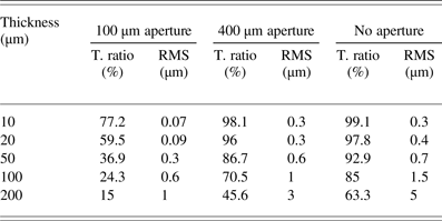
As illustrated in Table 1 and Figure 5, a high resolution in order of micron can be achieved with the prototype magnet imaging system, no matter an aperture is set in the trajectory or not. The transmission ratio (T. Ratio in Table 1) is high even in case that a very small aperture, for example 100 µm in diameter, is set in the central trajectory. This indicates that, the aperture will not reduce the brightness of the image too much, but will reduce the unwanted background like γ or X rays remarkably, since the solid angle subtending to the target is in order of 10−11 sr. The results also show that, a proper aperture is crucial to improve the spatial resolution, and it is also able to adjust the dynamic responding range of the radiography, so the calibrated intensity ratio can be used to measure the thickness of the target. The beam intensity in the simulations is 109 electrons/mm2, which indicates that charge of nC/pulse is suitable for a mm scale target. It needs to be noted that, in case that very strong magnet fields exist in the target region (Schumaker et al., Reference Schumaker, Nakanii, Mcguffey, Zulick, Chyvkov, Dollar, Habara, Kalintchenko, Maksimchuk, Tanaka, Thomas, Yanovsky and Krushelnick2013), the particle tracing codes can be taken into account, so that the rapidly evolving field structures can be probed as well.
Fig. 5. Projection of the target image on X-axis obtained with the prototype system in Fig. 4.
Table 1. Transmission ratio and root mean square (RMS) resolution for 800 MeV electron radiography
3. CONCLUSION
We have presented a conceptual design of an electron radiography system for dynamic diagnostics of HED matter. The scheme has its distinct advantages as follows: (1) As an universal imaging-light-source, multiple electron bunches have a very flexible time structure, and they can be easily transported with mature RF photocathode-based electron beam technology, so there is great possibility to get the multiple dynamic images with ps accuracy in three orthogonal directions simultaneously during one experimental event; (2) by using a proper magnet imaging system, unprecedented spatial resolution can be achieved with high energy (several hundred MeV or GeV) electron beams; (3) dynamic responding range of the high energy electron radiography system is related with a collimating aperture, so through adjusting the aperture, the density and thickness information of the target could be measured in its concerned range; (4) the unwanted background from the target can be remarkably reduced by an aperture and the imaging electrons will keep in the same order meanwhile, so high signal to noise ratio can be expected. A successful implementation of this scheme may have a major impact on HEDP research or some other fields, which needs a microscopy study in picosecond accuracy and in a wide dynamic range. An 800 MeV electron radiography system has been proposed at the High Intensity heavy-ion-Accelerator Facility (a future project) where HEDP is one of the main scientific goals (Zhao et al., Reference Zhao, Cheng, Wang, Zhou, Lei, Sun, Xu, Ren, Sheng, Zhang and Xiao2014). An engineering design of this system is under development.
ACKNOWLEDGEMENTS
We acknowledge useful discussions with Joe Kwan of LBL, Andrew NG from UBC, Paul Schoessow from Euclid Techlabs, Frank Miller from LANL, Siegfried Glenzer from SLAC and Dieter Hoffmann from TU Darmstadt. Special thanks to W. Liu of ANL for providing the EGS4 simulations. This work is partially supported by the US Department of Energy under contract No. DE-AC02-06CH11357, Scientific Research Program of Education Bureau of Shaanxi Province, China (Grant No. 2010JK895), Scientific Research Program Funded by Shaanxi Provincial Education Department (Program No. 15JK1793), and National Natural Science Foundation of China (No.11435015, No. 11375138, No. U1532263, No. 11505251, No.11505248 No. 11275241,)