Published online by Cambridge University Press: 02 June 2005
The Vulcan Nd:glass laser at the Central Laser Facility (CLF) is a petawatt (1015 Watts) interaction facility, designed to deliver irradiance on target of 1021W.cm−2 for the UK and international user community. The facility came online to users in 2002 and considerable experience has been gained operating Vulcan in this mode. The facility delivers a wide-ranging experimental program in fundamental physics and advanced applications. This includes the interaction of ultrahigh intensity light with matter, fast ignition fusion research, photon induced nuclear reactions, electron and ion acceleration by light waves, and the exploration of the exotic world of plasma physics dominated by relativity. We report on the first year's operation of the facility and the highlights of the experimental campaigns.
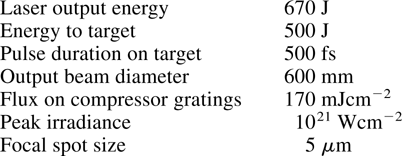
In 1998, the science program based on the Vulcan facility was achieving an unprecedented level of success with high profile scientific publications across a wide range of topics. In particular, the Central Laser Facility (CLF) was recognized as a world leading centre for high irradiance interaction experiments using its 100 TW (Danson et al., 1998) Chirped Pulse Amplification (CPA) beam-line (Strickland & Mourou, 1985). In response to user demand, a CLF team devised an upgrade strategy for Vulcan with the aim of delivering Petawatt power from an enhanced CPA beam. The specification was defined as:

The Petawatt beam line was funded through an Engineering and Physical Sciences Research Council (EPSRC) Standard Research Grant (GR/M48383) as the first in a two-step development strategy. The system development was also made possible through the transfer of amplifiers and pulse power equipment from Lawrence Livermore National Laboratory (LLNL) following the closure of the Nova laser facility.
The Petawatt laser facility was successfully commissioned in 2002 with user experiments beginning in November 2002. User experiments were preceded by a commissioning experiment which verified the system performance and radiation shielding.
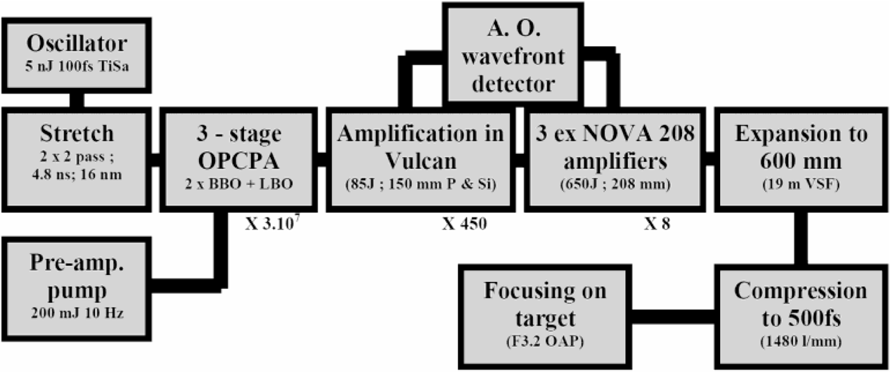
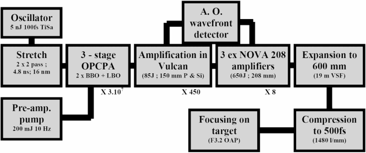
The layout of the Petawatt facility is shown in Figure 1 illustrating the major constituent components.

Building blocks of the petawatt Facility.
The pulse generator for the system is a commercially available Ti:Sapphire oscillator operating at ∼1055 nm and delivering pulses of ∼120 fs in duration. A double passed Offner triplet stretcher was designed and implemented, which offered an intrinsically small system which with the correct choice of optics is aberration free. It included a single large area 1480 lines/mm gold coated holographic grating, which provides automatic matching between the different passes of the stretcher. The focusing optics comprise of 300 mm diameter concave mirrors with a focal length of 2250 mm, matched to 120 mm diameter convex mirrors with half the primary optics focal length.
The baseline specification for the Vulcan upgrade is 500 J delivered to a target with pulse duration of 500 fs. This performance is not achievable by amplification solely by Nd:Glass amplifiers, since gain narrowing would reduce the pulse bandwidth to a value below the ∼ 4 nm limit which is required to support a 500 fs pulse duration. The approach taken for the Petawatt was to use a pre-amplification system, OPCPA, which generates pulses of ∼10 mJ at large bandwidth (1 mJ/nm) for injection into the Vulcan rod and disc amplifier chain. The system uses a customized 2 J, 1053 nm, 10 Hz Nd:YAG laser to generate a 4.5 ns frequency doubled 200–300 mJ pump pulse which is approximately “top-hat” in both space and time. This pumps a three-stage optical parametric amplifier (Collier et al., 1999) that is seeded by the stretched oscillator pulse. The non-linear medium used for the three amplification stages is β-Barium Borate (BBO), each crystal being maintained in an oven at 40°C.
The Petawatt system utilizes an existing beam-line of the Vulcan laser used for the 100 TW beam-line (Danson et al., 1998). The amplifier chain is optimized for bandwidth using a combination of Nd:Phosphate and Nd:Silicate amplifying media with the silicate installed on small aperture high gain amplifiers. The additional energy required for the Petawatt is obtained from an extra disc amplifier stage comprising three ex-NOVA 208 mm aperture disc amplifiers. The 208 mm amplifiers were modified to operate with four flash-lamp circuits using an increased lamp bore to be compatible with Vulcan's existing pulse power system. Its small signal gain was measured to be 2.23, narrow bandwidth 1053 nm operation, falling to approximately 2.0 under saturation conditions for 670 J total output. This performance was consistent with the requirements of the Petawatt beam-line and all of the amplifiers were subsequently modified. Gain isolation is provided by a 208 mm aperture Faraday rotator and a single polarizer at the stage input.
A large aperture, 120 mm diameter, adaptive optics (AO) module was developed to improve the wave-front quality to obtain the optimum focal spot on targets. In addition, the AO has assisted achieving the best possible recompression of the stretched pulse. The wave-front errors that need to be corrected arise from static aberrations of the optics in the beam-line and distortions caused by the thermal gradients set up in the amplifiers during the course of firing laser shots throughout the day. The deformable mirror has 61 addressable elements in a two-dimension (2D) array suitable for correcting slowly varying aberrations. With no phase correction, Vulcan already operates with a beam quality of approximately 3 times the diffraction limit, and reduction by a factor of 2 gives an increase in irradiance on targets of a factor of four. This is of significant benefit to the science program at CLF, the physics of which is very sensitive to irradiance.
Gold-coated holographic gratings (Fig. 2) of 940 mm diameter and a line density of 1480 lines/mm were supplied by LLNL under “Work for Others” collaboration. A grating geometry was used with an input operational angle of 48 degrees and a separation of 13 m. With a conservative operational fluency of 170 mJ/cm−2, to preserve the in-service lifetime of the gratings, and a beam diameter of 600 mm gave the required operational input energy of 670 J. Beam expansions from the 208 mm aperture final amplification stage to the 600 mm is achieved using a vacuum spatial filter working at F#25. The expanding spatial filter has an overall length of 19 m.

The 940 mm diameter gold coated diffraction gratings used in the pulse compression during an optical inspection.
A target chamber has been designed which combines the requirements for a versatile interaction geometry with the provision of substantial environmental shielding. Focusing on a target is achieved using a 620 mm diameter, 1.8 m focal length, and F#3.1 off-axis parabola. The parabola was silver coated with a magnesium fluoride protective overcoat.
The OPCPA system has been fully implemented within the Vulcan Front End. The system has demonstrated that the amplified 20 mJ output pulse has no loss of bandwidth with a gain in excess of 107. High stability of the output energy is an essential criterion for the pre-amplification in order to deliver pulses to target at close to the optical damage limit of the beam line. This requirement is met by operating the third amplification stage in saturation. The OPCPA system has demonstrated excellent stability with the occasional drop out due to the momentary loss of pump seeding—although no full energy shots failed due to this mechanism.
The laser chain extended with 208 amplifiers has delivered maximum beam energy in a narrow band-width pulse of 792 J, well in excess of the energy requirements of the beam-line.
Closed loop operation of the adaptive optics system on Vulcan with a cycle time > 1 Hz has produced correction from ∼3 to 1.5 times the diffraction limit and exhibits a high level of immunity to electrical noise.
Figure 3 gives a sample of the compressed pulse characterization carried out on a shot to shot basis. All the short pulse diagnostics are derived from a 1% transmission from the 940 mm diameter mirror after the second compressor grating. The captured near-field on a 375 TW shot in shown in Figure 3(a). The second order autocorrelation on this shot (Fig. 3(b)) gives a compressed pulse width of 800 fs.

(a) Shows a 1% transmitted near field image of the compressed pulse. (b) A line scans through the autocorrelation giving a pulse width of 800 fs. (c) a CW measurement of the focus spot.
Focusing on a target and hence optimization of the parabola was conducted using a 1053 nm CW alignment laser. This was injected into the beam-line at the entrance to the final beam expanding vacuum spatial filter. By injecting the CW beam at the smaller aperture meant that full aperture alignment could be carried out through the compressor and on to target with modest cost, and with confidence that it would be matched to the main laser beam.
The variation of the focal spot diameter was measured as a function of position along the optical axis using a microscope objective and a CCD camera. The result of the z-scan for the CW beam gave a best focus spot size of 5 μm FWHM in both the horizontal and vertical scans. This demonstrates a lack of significant astigmatism. A typical example of the images produced is shown in Figure 3c. On high energy shots an X-ray pinhole camera was used to observe the X-ray emission. An image size of ∼11 μm was recorded indicative of a smaller optical focal spot size in agreement with the low energy data.
The shielding requirement against radiation (γ-rays, neutrons, and activation) produced by Petawatt laser shots on a range of target materials was calculated using experimental electron energy flux distributions, and cross checked by scaling data from earlier experiments on Vulcan and other facilities at intensities approaching 1021 Wcm−2. For medium and high Z targets, a shield blanket of 15 cm lead and 10 cm of high density polyethylene, and a shielded fire escape door were required.
A 70 ton lead shield wall was installed surrounding the interaction chamber with gaps for access to the diagnostic ports. The 15 cm thick lead shield wall surrounding the chamber provides high γ-ray absorption and in combination with the 60 cm thick concrete walls surrounding the interaction area gives an attenuation of γ-rays with a minimum direct attenuation of 50,000 at 6 MeV.
In addition to the γ-ray shielding, a neutron absorbing and moderating blanket is required. A 10 cm thick high density polyethylene shroud was added to the chamber to fulfill this requirement.
In advance of any user experiments, a radiological survey had to be conducted to validate the Petawatt target area shielding effectiveness, and the performance of the focused beam on-target. Radiological dosimeter data (Fig. 4) demonstrated that the shielding was operating as required. The measurements were approved by the site Radiation Protection Advisor (RPA) for facility delivery to users. During this experiment, significant operational experience was gained in order that the first user experiment could be conducted with a high degree of confidence in the facility performance.

Dose Measurement of X-ray and Gamma ray emission from a Gold target.
The first user experiment on the Petawatt facility was conducted by Prof. K Krushelnick and colleagues of Imperial College in London, to investigate advanced particle acceleration schemes. The experiment used the f3.1 focusing parabola to produce a high intensity interaction in a Helium gas jet. Electrons produced in the interaction were measured using an on-axis electron spectrometer. The experiment produced some exciting data achieving world leading electron acceleration results. With the gas jet producing an optimum density of 7.7 × 1018 cm−3 the electron spectrum was recorded with a peak energy of 350 MeV.
Researchers from AWE, Aldermaston used Vulcan Petawatt to investigate the electron transport in targets by observing the heating of a buried layer of aluminium beneath varying thicknesses of plastic. The temperature was recorded by observing the resonance lines of H-like and He-like emission coming from the back of the target. For a plastic thickness 4 microns of a temperature of 600 eV was recorded. As the thickness of plastic increased to 17 μm the temperature fell in line with expectation. For thicknesses >17 μm no line spectra was observed indicating a much lower temperature. LSP (Welch et al., 2001) simulations show that this situation can be observed if a prepulse were present at the 10−7 level, 2 ns ahead of the interaction pulse. This produces an electric field inhibiting the electron transport.
Ledingham et al. (2003) from the University of Strathclyde studied laser driven photo transmutation of materials. If the Petawatt beam is incident on a gold foil, at intensities in excess of 1020 Wcm−2, a γ-ray beam is produced in the forward beam direction. A second target can be placed on this beam and the half lives of species measured following the shot. Iodine-129, an isotope relevant to the nuclear industry, has a half-life of 15.7 million years. When this was irradiated by the γ-ray beam decay measurements showed the presence of Iodine-128 which has a half life of ∼26 minutes. This is an important result demonstrating the transmutation of fission by product in to a safe isotope.
Dr. P. Norreys, Central Laser Facility, and his team commissioned LaNSA (Habara et al., 2003), two 256 element neutron time-of-flight detector, arrays in the Petawatt target area (Fig. 5). These were designed to study ion temperature and momentum distributions from beam fusion reactions. A Petawatt interaction experiment was carried out to investigate energy transport processes. The interaction beam was incident on a plastic target whose thickness could be varied beneath which a layer of deuterated plastic was placed. The measurements are consistent with resistive heating by the return current for temperatures = 1 KeV and previous measurements with the 100 TW laser.

The LaNSA neutron detector array.
Prof. O. Willi et al., from the University of Dusseldorf in Germany, studied electron beam transport through low density foams with particular relevance to the fast igniter fusion (Tabak et al., 1994) scheme. Foams of different lengths and densities were used. The interaction of the leading edge of the pulse with the gold coated target surface launched an ionization wave which had the effect of preionizing the foam. The electrons reaching the rear side of the target were diagnosed by imaging, the optical transition radiation (OTR) with micron scale resolution. These high-resolution images clearly showed filamentary structures organized in a ring-like structure of larger filaments around the laser axis. Electron spectra data yielded an electron temperature of about 7 MeV. Preliminary three-dimension (3D) PIC code simulations, by Prof. A. Pukhov, from the University of Dusseldorf, to analyze and interpret the experimental results are in good qualitative agreement with the experimental data.
An experiment led by LLNL was a large multi-institutional effort, which included teams from LLNL, the Laboratory for Laser Energetic (Rochester, NY), UC Davis (CA), General Atomics (San Diego, CA), AWE (Aldermaston), and Queen's University in Belfast, UK. LLNL has several programs relating to high-intensity laser-interaction physics. Several of these programs, including high energy X-ray radiography, thermal X-ray backlighting, and fast ignition are being developed in conjunction with experiments to be fielded on a future high-energy short-pulse Petawatt-class capability on a National Ignition Facility (NIF). The RAL Petawatt campaign provided an opportunity to further these investigations experimentally at laser conditions similar to those which may be achieved on NIF. A very broad based experimental campaign investigated fundamental laser-matter interaction processes at relativistic intensities, K-alpha and thermal broadband X-ray generation, electron energy transport, and particle generation (protons, electrons, and neutrons).
A 3D CAD drawing of the experimental setup is shown in Figure 6. Nineteen diagnostics were fielded in the Petawatt chamber. A number of single-photon counting X-ray CCD detectors and imaging X-ray cameras were used to measure the absolute flux and source size of K-alpha X-rays (at 22 KeV for Ag). An XUV imaging detector and streak camera were used to measure thermal radiation produced in targets from electron and proton heating. A frequency-doubled interferometer and electron spectrometer provided data on the laser interaction conditions, and electron acceleration. All of these, as well as the other diagnostics, were fielded on every shot resulting in a very substantive data set, which is currently under analysis.

The complex diagnostics set up used for the LLNL petawatt interaction experiment.
The Petawatt interaction facility (Fig. 7) at the Central Laser Facility, CCLRC Rutherford Appleton Laboratory has been in operation in excess of one year. Several major experiments have been conducted by UK and international research teams. These have proved very productive and will lead to publications at the highest level. The facility is currently operating up to 500 TW with a focal intensity of 5 × 10²⁰ Wcm−2. The ramp up in power will continue to the Petawatt level and plans for the future development of the facility include the addition of 1 ns “long pulse” beams and auxiliary probes for target compression, probing and backlighting.

The petawatt Facility prior to the installation of the target chamber radiation shielding.

Building blocks of the petawatt Facility.

The 940 mm diameter gold coated diffraction gratings used in the pulse compression during an optical inspection.

(a) Shows a 1% transmitted near field image of the compressed pulse. (b) A line scans through the autocorrelation giving a pulse width of 800 fs. (c) a CW measurement of the focus spot.

Dose Measurement of X-ray and Gamma ray emission from a Gold target.

The LaNSA neutron detector array.

The complex diagnostics set up used for the LLNL petawatt interaction experiment.

The petawatt Facility prior to the installation of the target chamber radiation shielding.