


1 Introduction
Elastic-plated gravity currents involve the spreading of viscous material beneath an elastic sheet. The applications range from the emplacement of magma in the shallow crust (Bunger & Cruden Reference Bunger and Cruden2011; Michaut Reference Michaut2011) and gravity-driven lava flows under a solidified crust at the surface (Slim et al. Reference Slim, Balmforth, Craster and Miller2009; Hewitt, Balmforth & De Bruyn Reference Hewitt, Balmforth and De Bruyn2015) in geosciences to the manufacture of flexible electronics and microelectromechanical systems in engineering (Hosoi & Mahadevan Reference Hosoi and Mahadevan2004).
When the thickness of the flow is small compared to its extent, the lubrication approximation applies and the study of elastic-plated gravity currents amounts to the study of a sixth-order nonlinear diffusion equation for the flow thickness
 $h$
(Michaut Reference Michaut2011; Lister, Peng & Neufeld Reference Lister, Peng and Neufeld2013; Hewitt et al.
Reference Hewitt, Balmforth and De Bruyn2015). Nonetheless, this equation is degenerate at the contact line, i.e. where
$h$
(Michaut Reference Michaut2011; Lister, Peng & Neufeld Reference Lister, Peng and Neufeld2013; Hewitt et al.
Reference Hewitt, Balmforth and De Bruyn2015). Nonetheless, this equation is degenerate at the contact line, i.e. where
 $h\rightarrow 0$
, and there cannot be any advancing solutions (Flitton & King Reference Flitton and King2004; Lister et al.
Reference Lister, Peng and Neufeld2013; Hewitt et al.
Reference Hewitt, Balmforth and De Bruyn2015). This problem is similar to the well-known problem for surface-tension-driven flow where full continuum theories of fluid mechanics are unable to describe the flow near the contact line without introducing molecular-scale physics (Bertozzi Reference Bertozzi1998).
$h\rightarrow 0$
, and there cannot be any advancing solutions (Flitton & King Reference Flitton and King2004; Lister et al.
Reference Lister, Peng and Neufeld2013; Hewitt et al.
Reference Hewitt, Balmforth and De Bruyn2015). This problem is similar to the well-known problem for surface-tension-driven flow where full continuum theories of fluid mechanics are unable to describe the flow near the contact line without introducing molecular-scale physics (Bertozzi Reference Bertozzi1998).
For practical purposes, different forms of regularization at the tip have been proposed such as the introduction of a thin prewetting film of fluid of initially constant thickness or the use of a fluid lag filled with gas at constant pressure (Lister et al. Reference Lister, Peng and Neufeld2013; Hewitt et al. Reference Hewitt, Balmforth and De Bruyn2015; Peng et al. Reference Peng, Pihler-Puzović, Juel, Heil and Lister2015; Pihler-Puzović et al. Reference Pihler-Puzović, Juel, Peng and Heil2015). While both alternatives suffer from depending on the parameter introduced by the regularization itself, i.e. the thickness of the prewetting film or the pressure within the gap, the prewetting film regularization approach allows us to more easily introduce fluid cooling in the problem and is used here.
The dynamics of the spreading for a Newtonian fluid with a constant viscosity has been thoroughly described in an axisymmetric geometry (Michaut Reference Michaut2011; Lister et al.
Reference Lister, Peng and Neufeld2013; Thorey & Michaut Reference Thorey and Michaut2014; Hewitt et al.
Reference Hewitt, Balmforth and De Bruyn2015) and shows two distinct asymptotic regimes. First, gravity is negligible and the peeling of the front is driven by bending of the overlying layer; the interior is bell shaped, the radius evolves as
 $\widetilde{h_{f}}^{1/22}t^{7/22}$
and the thickness at the centre as
$\widetilde{h_{f}}^{1/22}t^{7/22}$
and the thickness at the centre as
 $\widetilde{h_{f}}^{-2/22}t^{8/22}$
where
$\widetilde{h_{f}}^{-2/22}t^{8/22}$
where
 $\widetilde{h_{f}}$
is the prewetting film thickness. When the radius becomes larger than
$\widetilde{h_{f}}$
is the prewetting film thickness. When the radius becomes larger than
 $4{\mathcal{L}}$
, where
$4{\mathcal{L}}$
, where
 ${\mathcal{L}}$
is the flexural wavelength of the upper elastic layer, the weight of the current becomes dominant over the bending terms and the flow enters a gravity current regime (Huppert Reference Huppert1982b
). In this regime, the thickness profile develops a flat top with bent edges, the radius evolves as
${\mathcal{L}}$
is the flexural wavelength of the upper elastic layer, the weight of the current becomes dominant over the bending terms and the flow enters a gravity current regime (Huppert Reference Huppert1982b
). In this regime, the thickness profile develops a flat top with bent edges, the radius evolves as
 $t^{1/2}$
while the thickness tends to a constant. Different analogue experiments of isoviscous flows confirm these theoretical results (Dixon & Simpson Reference Dixon and Simpson1987; Lister et al.
Reference Lister, Peng and Neufeld2013).
$t^{1/2}$
while the thickness tends to a constant. Different analogue experiments of isoviscous flows confirm these theoretical results (Dixon & Simpson Reference Dixon and Simpson1987; Lister et al.
Reference Lister, Peng and Neufeld2013).
However, in most geological settings, the isothermal/isoviscous assumptions are not valid. For instance, the viscosity of magmas can vary by several orders of magnitude (Shaw Reference Shaw1972; Lejeune & Richet Reference Lejeune and Richet1995). Therefore, as the fluid flows and cools down, its composition and crystal content change, which in turn modifies its viscosity and dynamics. Several studies have shown that, in a gravity current, this coupling between cooling and flow results in important deviations from the isoviscous case (Bercovici Reference Bercovici1994; Bercovici & Lin Reference Bercovici and Lin1996; Balmforth, Craster & Sassi Reference Balmforth, Craster and Sassi2004; Garel et al. Reference Garel, Kaminski, Tait and Limare2014).
In this paper, we examine how the spreading of an elastic-plated gravity current is affected by its cooling. In particular, we account for the temperature dependence of the viscosity. This gives rise to a set of two coupled nonlinear equations that we solve numerically. We characterize the flow thermal structure and its effect on the dynamics via its rheology
 $\unicode[STIX]{x1D702}(T)$
in each regime separately. In both regimes, we identify different thermal phases of propagation that we characterize by different time scales and scaling laws.
$\unicode[STIX]{x1D702}(T)$
in each regime separately. In both regimes, we identify different thermal phases of propagation that we characterize by different time scales and scaling laws.
2 Theory
2.1 Formulation
We model the axisymmetric flow of fluid below an elastic layer of constant thickness
 $d_{c}$
and above a rigid layer (figure 1). To avoid problem at the contact line, we consider a thin, initially cold, prewetting film of thickness
$d_{c}$
and above a rigid layer (figure 1). To avoid problem at the contact line, we consider a thin, initially cold, prewetting film of thickness
 $\widetilde{h_{f}}$
and temperature
$\widetilde{h_{f}}$
and temperature
 $T_{0}$
(figure 1). The case of an initially hot prewetting film is treated in appendix C.
$T_{0}$
(figure 1). The case of an initially hot prewetting film is treated in appendix C.
The hot fluid is injected continuously at the base and centre of the current at a constant rate
 $Q_{0}$
and constant temperature
$Q_{0}$
and constant temperature
 $T_{i}$
through a conduit of diameter
$T_{i}$
through a conduit of diameter
 $a$
. We assume a Poiseuille flow within the cylindrical feeding conduit such that the injection velocity
$a$
. We assume a Poiseuille flow within the cylindrical feeding conduit such that the injection velocity
 $w_{i}$
reads
$w_{i}$
reads
 $$\begin{eqnarray}\displaystyle w_{i}(r,t)=\mathscr{H}\left(\frac{a}{2}-r\right)\frac{\unicode[STIX]{x0394}P}{4\unicode[STIX]{x1D702}_{h}Z_{c}}\left(\frac{a^{2}}{4}-r^{2}\right), & & \displaystyle\end{eqnarray}$$
where
 $\unicode[STIX]{x0394}P/Z_{c}$
is the pressure gradient driving the flow in the feeding conduit and
$\unicode[STIX]{x0394}P/Z_{c}$
is the pressure gradient driving the flow in the feeding conduit and
 $\unicode[STIX]{x1D702}_{h}$
is the viscosity of the hottest fluid at the temperature
$\unicode[STIX]{x1D702}_{h}$
is the viscosity of the hottest fluid at the temperature
 $T_{i}$
. The fluid cools through the top and bottom boundaries by conduction in the surrounding medium, whose temperature is maintained constant and equal to
$T_{i}$
. The fluid cools through the top and bottom boundaries by conduction in the surrounding medium, whose temperature is maintained constant and equal to
 $T_{0}$
. For simplicity, heating and melting of the surrounding medium are neglected.
$T_{0}$
. For simplicity, heating and melting of the surrounding medium are neglected.

Figure 1. Model geometry and parameters. The vertical scale is exaggerated. Left upper panels: temperature profiles with merged (
 $r=r_{a}$
) and separated (
$r=r_{a}$
) and separated (
 $r=r_{b}$
) thermal boundary layers.
$r=r_{b}$
) thermal boundary layers.
As it cools, the viscosity of the fluid increases following an inverse dependence on the temperature
 $$\begin{eqnarray}\displaystyle \unicode[STIX]{x1D702}(T)=\frac{\unicode[STIX]{x1D702}_{h}\unicode[STIX]{x1D702}_{c}(T_{i}-T_{0})}{\unicode[STIX]{x1D702}_{h}(T_{i}-T_{0})+(\unicode[STIX]{x1D702}_{c}-\unicode[STIX]{x1D702}_{h})(T-T_{0})}, & & \displaystyle\end{eqnarray}$$
where
 $\unicode[STIX]{x1D702}_{c}$
is the viscosity of the coldest fluid at
$\unicode[STIX]{x1D702}_{c}$
is the viscosity of the coldest fluid at
 $T=T_{0}$
(Bercovici Reference Bercovici1994).
$T=T_{0}$
(Bercovici Reference Bercovici1994).
This rheology has the advantage of restricting strong viscosity variations over a small range of temperature close to
 $T_{0}$
while still capturing the essential behaviour of a viscous fluid, i.e. the viscosity variations are the largest where the temperature is the coldest (Shaw Reference Shaw1972; Marsh Reference Marsh1981; Lejeune & Richet Reference Lejeune and Richet1995; Giordano, Russell & Dingwell Reference Giordano, Russell and Dingwell2008).
$T_{0}$
while still capturing the essential behaviour of a viscous fluid, i.e. the viscosity variations are the largest where the temperature is the coldest (Shaw Reference Shaw1972; Marsh Reference Marsh1981; Lejeune & Richet Reference Lejeune and Richet1995; Giordano, Russell & Dingwell Reference Giordano, Russell and Dingwell2008).
2.2 Pressure
The intrusion develops over a radius
 $R$
that is much larger than its thickness
$R$
that is much larger than its thickness
 $h$
(
$h$
(
 $R\gg h$
). In the laminar regime and in axisymmetrical coordinates (
$R\gg h$
). In the laminar regime and in axisymmetrical coordinates (
 $r$
,
$r$
,
 $z$
), the Navier–Stokes equations within the lubrication approximation are
$z$
), the Navier–Stokes equations within the lubrication approximation are
 $$\begin{eqnarray}\displaystyle & \displaystyle -\frac{\unicode[STIX]{x2202}P}{\unicode[STIX]{x2202}r}+\frac{\unicode[STIX]{x2202}}{\unicode[STIX]{x2202}z}\left(\unicode[STIX]{x1D702}(T)\frac{\unicode[STIX]{x2202}u}{\unicode[STIX]{x2202}z}\right)=0 & \displaystyle\end{eqnarray}$$
 $$\begin{eqnarray}\displaystyle & \displaystyle -\frac{\unicode[STIX]{x2202}P}{\unicode[STIX]{x2202}z}-\unicode[STIX]{x1D70C}_{m}g=0, & \displaystyle\end{eqnarray}$$
 $u(r,z,t)$
is the radial velocity,
$u(r,z,t)$
is the radial velocity,
 $\unicode[STIX]{x1D70C}_{m}$
the fluid density,
$\unicode[STIX]{x1D70C}_{m}$
the fluid density,
 $g$
the standard acceleration due to gravity and
$g$
the standard acceleration due to gravity and
 $P(r,z,t)$
the pressure within the fluid. Integration of (2.4) gives the dynamic pressure
$P(r,z,t)$
the pressure within the fluid. Integration of (2.4) gives the dynamic pressure
 $P(r,z,t)$
within the flow, which, given that the vertical deflection
$P(r,z,t)$
within the flow, which, given that the vertical deflection
 $h(r,t)$
of the upper elastic layer is small compared to its thickness
$h(r,t)$
of the upper elastic layer is small compared to its thickness
 $d_{c}$
, i.e.
$d_{c}$
, i.e.
 $h\ll d_{c}$
, can be written (Michaut Reference Michaut2011)
$h\ll d_{c}$
, can be written (Michaut Reference Michaut2011)  $$\begin{eqnarray}\displaystyle P=\unicode[STIX]{x1D70C}_{m}g(h-z)+B\unicode[STIX]{x1D6FB}_{r}^{4}h, & & \displaystyle\end{eqnarray}$$
with
 $$\begin{eqnarray}\displaystyle \unicode[STIX]{x1D6FB}_{r}^{4}h=\frac{1}{r}\frac{\unicode[STIX]{x2202}}{\unicode[STIX]{x2202}r}\left(r\frac{\unicode[STIX]{x2202}}{\unicode[STIX]{x2202}r}\left(\frac{1}{r}\frac{\unicode[STIX]{x2202}}{\unicode[STIX]{x2202}r}\left(r\frac{\unicode[STIX]{x2202}h}{\unicode[STIX]{x2202}r}\right)\right)\right), & & \displaystyle\end{eqnarray}$$
where
 $h(r,t)$
is the flow thickness and
$h(r,t)$
is the flow thickness and
 $B$
is the bending stiffness of the thin elastic layer, that depends on Young’s modulus
$B$
is the bending stiffness of the thin elastic layer, that depends on Young’s modulus
 $E$
, Poisson’s ratio
$E$
, Poisson’s ratio
 $\unicode[STIX]{x1D708}^{\ast }$
and on the elastic layer thickness
$\unicode[STIX]{x1D708}^{\ast }$
and on the elastic layer thickness
 $d_{c}$
as
$d_{c}$
as
 $B=Ed_{c}^{3}/(12(1-\unicode[STIX]{x1D708}^{\ast 2}))$
.
$B=Ed_{c}^{3}/(12(1-\unicode[STIX]{x1D708}^{\ast 2}))$
.
2.3 Heat transport equation
2.3.1 Local energy conservation
In the laminar regime and in axisymmetrical coordinates (
 $r$
,
$r$
,
 $z$
), the local energy conservation equation within the lubrication assumption is
$z$
), the local energy conservation equation within the lubrication assumption is
 $$\begin{eqnarray}\displaystyle \frac{\text{D}}{\text{D}t}(\unicode[STIX]{x1D70C}_{m}C_{p,m}T+\unicode[STIX]{x1D70C}_{m}L(1-\unicode[STIX]{x1D719}))=k_{m}\frac{\unicode[STIX]{x2202}^{2}T}{\unicode[STIX]{x2202}z^{2}}, & & \displaystyle\end{eqnarray}$$
where
 $T(r,z,t)$
is the fluid temperature and
$T(r,z,t)$
is the fluid temperature and
 $\unicode[STIX]{x1D70C}_{m}$
,
$\unicode[STIX]{x1D70C}_{m}$
,
 $k_{m}$
and
$k_{m}$
and
 $C_{p,m}$
are the density, thermal conductivity and specific heat of the fluid. Here, we also account for energy release by possible crystallization of the fluid, which is a non-negligible source of heat in the case of magmas;
$C_{p,m}$
are the density, thermal conductivity and specific heat of the fluid. Here, we also account for energy release by possible crystallization of the fluid, which is a non-negligible source of heat in the case of magmas;
 $\unicode[STIX]{x1D719}(r,z,t)$
is the crystal fraction in the melt and
$\unicode[STIX]{x1D719}(r,z,t)$
is the crystal fraction in the melt and
 $L$
the latent heat of crystallization. In this model, the crystals are only considered as a source/sink of energy as they melt/form at equilibrium during the flow as we assume that the physical properties of the crystal liquid mixture are the same as that of the fluid.
$L$
the latent heat of crystallization. In this model, the crystals are only considered as a source/sink of energy as they melt/form at equilibrium during the flow as we assume that the physical properties of the crystal liquid mixture are the same as that of the fluid.
The fluid temperature varies between its liquidus
 $T_{L}$
and solidus temperature
$T_{L}$
and solidus temperature
 $T_{S}$
, i.e.
$T_{S}$
, i.e.
 $T_{i}=T_{L}$
and
$T_{i}=T_{L}$
and
 $T_{0}=T_{S}$
. As
$T_{0}=T_{S}$
. As
 $T_{0}$
is also the fixed temperature of the surrounding medium in this model, this is equivalent to considering a fluid/wall interface pinned near the bulk freezing temperature
$T_{0}$
is also the fixed temperature of the surrounding medium in this model, this is equivalent to considering a fluid/wall interface pinned near the bulk freezing temperature
 $T_{S}$
of the fluid. In making this assumption, we neglect the heat flux necessary to heat up the wall up to
$T_{S}$
of the fluid. In making this assumption, we neglect the heat flux necessary to heat up the wall up to
 $T_{S}$
.
$T_{S}$
.
Following a common approximation, we assume that the crystal fraction is a linear function of temperature over the melting interval (Hort Reference Hort1997; Michaut & Jaupart Reference Michaut and Jaupart2006)
 $$\begin{eqnarray}\displaystyle \unicode[STIX]{x1D719}=\frac{T_{L}-T}{T_{L}-T_{s}}=\frac{T_{i}-T}{T_{i}-T_{0}}. & & \displaystyle\end{eqnarray}$$
With these approximations, the local energy equation (2.7) becomes
 $$\begin{eqnarray}\displaystyle \frac{\unicode[STIX]{x2202}T}{\unicode[STIX]{x2202}t}+u\frac{\unicode[STIX]{x2202}T}{\unicode[STIX]{x2202}r}+w\frac{\unicode[STIX]{x2202}T}{\unicode[STIX]{x2202}z}=\frac{St}{St+1}\unicode[STIX]{x1D705}_{m}\frac{\unicode[STIX]{x2202}^{2}T}{\unicode[STIX]{x2202}z^{2}}, & & \displaystyle\end{eqnarray}$$
where
 $u(r,z,t)$
and
$u(r,z,t)$
and
 $w(r,z,t)$
are the radial and vertical fluid velocities,
$w(r,z,t)$
are the radial and vertical fluid velocities,
 $St=(C_{p,m}(T_{i}-T_{0}))/L$
is the Stefan number which represents the ratio of sensible heat between solidus and liquidus to the total energy of the fluid at the liquidus temperature and
$St=(C_{p,m}(T_{i}-T_{0}))/L$
is the Stefan number which represents the ratio of sensible heat between solidus and liquidus to the total energy of the fluid at the liquidus temperature and
 $\unicode[STIX]{x1D705}_{m}$
is the fluid thermal diffusivity
$\unicode[STIX]{x1D705}_{m}$
is the fluid thermal diffusivity
 $\unicode[STIX]{x1D705}_{m}=k_{m}/(\unicode[STIX]{x1D70C}_{m}C_{p,m})$
. In particular, equation (2.9) shows that considering the energy released by crystallization is simply equivalent to considering a reduced thermal diffusivity
$\unicode[STIX]{x1D705}_{m}=k_{m}/(\unicode[STIX]{x1D70C}_{m}C_{p,m})$
. In particular, equation (2.9) shows that considering the energy released by crystallization is simply equivalent to considering a reduced thermal diffusivity
 $\widetilde{\unicode[STIX]{x1D705}_{m}}$
, which reads
$\widetilde{\unicode[STIX]{x1D705}_{m}}$
, which reads
 $$\begin{eqnarray}\displaystyle \widetilde{\unicode[STIX]{x1D705}_{m}}=\frac{St}{St+1}\unicode[STIX]{x1D705}_{m}, & & \displaystyle\end{eqnarray}$$
in the heat transport equation.
We use an integral balance method of heat transfer theory to approximately solve equation (2.9). In this method, that is developed below, the vertical structure of the temperature field is represented by a known function of depth that approximates the expected solution (Goodman Reference Goodman1958). Previous works on the cooling of lava domes at the surface have shown that such a reduction efficiently reduces the computation time while keeping the full dynamics of the unsimplified equation (2.9) well resolved (Balmforth et al. Reference Balmforth, Craster and Sassi2004). We use different kinds of vertical temperature profiles and show in appendix A that they all lead to very similar results.
2.3.2 Integral balance solution for the temperature
 $T(r,z,t)$

We model the cooling of the flow through the growth of two thermal boundary layers: one growing downward from the top and a second growing upward from the base. As we assume a fixed temperature at the boundary, the two thermal boundary layers grow symmetrically and have the same thickness
 $\unicode[STIX]{x1D6FF}(r,t)$
(figure 1). A popular approximation for the vertical temperature profile
$\unicode[STIX]{x1D6FF}(r,t)$
(figure 1). A popular approximation for the vertical temperature profile
 $T(r,z,t)$
is
$T(r,z,t)$
is
 $$\begin{eqnarray}\displaystyle T=\left\{\begin{array}{@{}ll@{}}T_{b}-(T_{b}-T_{0})\left(1-\displaystyle \frac{z}{\unicode[STIX]{x1D6FF}}\right)^{n}\quad & 0\leqslant z\leqslant \unicode[STIX]{x1D6FF}\\ T_{b}\quad & \unicode[STIX]{x1D6FF}\leqslant z\leqslant h-\unicode[STIX]{x1D6FF}\\ T_{b}-(T_{b}-T_{0})\left(1-\displaystyle \frac{h-z}{\unicode[STIX]{x1D6FF}}\right)^{n}\quad & h-\unicode[STIX]{x1D6FF}\leqslant z\leqslant h,\end{array}\right. & & \displaystyle\end{eqnarray}$$
where
 $T_{b}(r,t)$
is the temperature at the centre of the flow and
$T_{b}(r,t)$
is the temperature at the centre of the flow and
 $n>1$
(Balmforth et al.
Reference Balmforth, Craster and Sassi2004). This approximation captures the essential behaviour of the thermal structure: cooling is concentrated at the upper and bottom interfaces and cold boundary layers grow into the fluid interior as it flows. In addition, this profile assures the continuity of the temperature and heat flux within the flow.
$n>1$
(Balmforth et al.
Reference Balmforth, Craster and Sassi2004). This approximation captures the essential behaviour of the thermal structure: cooling is concentrated at the upper and bottom interfaces and cold boundary layers grow into the fluid interior as it flows. In addition, this profile assures the continuity of the temperature and heat flux within the flow.
While higher-order contributions to the temperature field, i.e. with
 $n>2$
, may also exist in certain situations, a parabolic profile is the most natural choice and we use
$n>2$
, may also exist in certain situations, a parabolic profile is the most natural choice and we use
 $n=2$
in the following (Bercovici Reference Bercovici1994; Bercovici & Lin Reference Bercovici and Lin1996). Nonetheless, the case of higher-order profiles are treated in appendix A and are shown not to influence the flow dynamics at least within the level of description adopted here.
$n=2$
in the following (Bercovici Reference Bercovici1994; Bercovici & Lin Reference Bercovici and Lin1996). Nonetheless, the case of higher-order profiles are treated in appendix A and are shown not to influence the flow dynamics at least within the level of description adopted here.
While the integral balance solution in (2.11) depends on two variables
 $T_{b}$
and
$T_{b}$
and
 $\unicode[STIX]{x1D6FF}$
that have to be consistently determined, these two variables are not independent. Indeed, in the flow region where thermal boundary layers exist, i.e. where
$\unicode[STIX]{x1D6FF}$
that have to be consistently determined, these two variables are not independent. Indeed, in the flow region where thermal boundary layers exist, i.e. where
 $\unicode[STIX]{x1D6FF}<h/2$
, the temperature
$\unicode[STIX]{x1D6FF}<h/2$
, the temperature
 $T_{b}$
is equal to the injection temperature
$T_{b}$
is equal to the injection temperature
 $T_{i}$
and
$T_{i}$
and
 $\unicode[STIX]{x1D6FF}$
is the unknown (figure 1,
$\unicode[STIX]{x1D6FF}$
is the unknown (figure 1,
 $r=r_{b}$
). In contrast, in the flow region where the thermal boundary layers have connected, which eventually arises at the current front,
$r=r_{b}$
). In contrast, in the flow region where the thermal boundary layers have connected, which eventually arises at the current front,
 $\unicode[STIX]{x1D6FF}=h/2$
and
$\unicode[STIX]{x1D6FF}=h/2$
and
 $T_{b}$
becomes the unknown (figure 1,
$T_{b}$
becomes the unknown (figure 1,
 $r=r_{a}$
).
$r=r_{a}$
).
2.3.3 Integral balance equation
We integrate the local energy conservation equation (2.9) separately over the two thermal boundary layers. The integration over the bottom thermal layer, from
 $z=0$
to
$z=0$
to
 $z=\unicode[STIX]{x1D6FF}$
gives
$z=\unicode[STIX]{x1D6FF}$
gives
 $$\begin{eqnarray}\displaystyle & & \displaystyle \frac{\unicode[STIX]{x2202}}{\unicode[STIX]{x2202}t}(\unicode[STIX]{x1D6FF}(\bar{T}-T_{b}))+\frac{1}{r}\frac{\unicode[STIX]{x2202}}{\unicode[STIX]{x2202}r}(r\unicode[STIX]{x1D6FF}(\overline{uT}-\bar{u}T_{b}))+\unicode[STIX]{x1D6FF}\left(\frac{\unicode[STIX]{x2202}T_{b}}{\unicode[STIX]{x2202}t}+\overline{u}\frac{\unicode[STIX]{x2202}T_{b}}{\unicode[STIX]{x2202}r}\right)\nonumber\\ \displaystyle & & \displaystyle \quad =-\widetilde{\unicode[STIX]{x1D705}_{m}}\left.\frac{\unicode[STIX]{x2202}T}{\unicode[STIX]{x2202}z}\right|_{z=0}+w_{i}(T_{i}-T_{b}),\end{eqnarray}$$
where the bar indicates a vertical average over the bottom thermal boundary layer
 $$\begin{eqnarray}\displaystyle \overline{f}=\frac{1}{\unicode[STIX]{x1D6FF}}\int _{0}^{\unicode[STIX]{x1D6FF}}f\,\text{d}z, & & \displaystyle\end{eqnarray}$$
 $T_{b}(r,t)$
is the temperature at
$T_{b}(r,t)$
is the temperature at
 $z=\unicode[STIX]{x1D6FF}$
and we have used the nullity of the thermal gradient at
$z=\unicode[STIX]{x1D6FF}$
and we have used the nullity of the thermal gradient at
 $z=\unicode[STIX]{x1D6FF}$
and the local mass conservation
$z=\unicode[STIX]{x1D6FF}$
and the local mass conservation
 $$\begin{eqnarray}\displaystyle \frac{1}{r}\frac{\unicode[STIX]{x2202}ru}{\unicode[STIX]{x2202}r}+\frac{\unicode[STIX]{x2202}w}{\unicode[STIX]{x2202}z}=0. & & \displaystyle\end{eqnarray}$$
The integration over the top thermal layer, from
 $z=h-\unicode[STIX]{x1D6FF}$
to
$z=h-\unicode[STIX]{x1D6FF}$
to
 $z=h$
gives
$z=h$
gives
 $$\begin{eqnarray}\displaystyle & & \displaystyle \frac{\unicode[STIX]{x2202}}{\unicode[STIX]{x2202}t}(\unicode[STIX]{x1D6FF}(\bar{T}-T_{b}))+\frac{1}{r}\frac{\unicode[STIX]{x2202}}{\unicode[STIX]{x2202}r}(r\unicode[STIX]{x1D6FF}(\overline{uT}-\bar{u}T_{b}))+\unicode[STIX]{x1D6FF}\left(\frac{\unicode[STIX]{x2202}T_{b}}{\unicode[STIX]{x2202}t}+\overline{u}\frac{\unicode[STIX]{x2202}T_{b}}{\unicode[STIX]{x2202}r}\right)\nonumber\\ \displaystyle & & \displaystyle \quad =\widetilde{\unicode[STIX]{x1D705}_{m}}\left.\frac{\unicode[STIX]{x2202}T}{\unicode[STIX]{x2202}z}\right|_{z=h},\end{eqnarray}$$
where, in addition to (2.14) and the fact that the thermal gradient at
 $z=h-\unicode[STIX]{x1D6FF}$
is equal to zero, we have used the kinematic boundary condition at
$z=h-\unicode[STIX]{x1D6FF}$
is equal to zero, we have used the kinematic boundary condition at
 $z=h(r,t)$
 $$\begin{eqnarray}\displaystyle \frac{\unicode[STIX]{x2202}h}{\unicode[STIX]{x2202}t}+u\frac{\unicode[STIX]{x2202}h}{\unicode[STIX]{x2202}r}=w. & & \displaystyle\end{eqnarray}$$
Adding (2.12) and (2.15) and using (2.11) with
 $n=2$
to derive the conductive fluxes, we finally obtain the heat balance equation which reads
$n=2$
to derive the conductive fluxes, we finally obtain the heat balance equation which reads
 $$\begin{eqnarray}\displaystyle & & \displaystyle \frac{\unicode[STIX]{x2202}}{\unicode[STIX]{x2202}t}(\unicode[STIX]{x1D6FF}(\bar{T}-T_{b}))+\frac{1}{r}\frac{\unicode[STIX]{x2202}}{\unicode[STIX]{x2202}r}(r\unicode[STIX]{x1D6FF}(\overline{uT}-\bar{u}T_{b}))+\unicode[STIX]{x1D6FF}\left(\frac{\unicode[STIX]{x2202}T_{b}}{\unicode[STIX]{x2202}t}+\overline{u}\frac{\unicode[STIX]{x2202}T_{b}}{\unicode[STIX]{x2202}r}\right)\nonumber\\ \displaystyle & & \displaystyle \quad =-2\widetilde{\unicode[STIX]{x1D705}_{m}}\frac{(T_{b}-T_{0})}{\unicode[STIX]{x1D6FF}}+\frac{w_{i}}{2}(T_{i}-T_{b}).\end{eqnarray}$$
2.3.4 Final heat transport equation
Equation (2.17) can be rewritten depending on the unknown in the temperature field
 $\unicode[STIX]{x1D6FF}$
or
$\unicode[STIX]{x1D6FF}$
or
 $T_{b}$
.
$T_{b}$
.
When
 $T_{b}=T_{i}$
and
$T_{b}=T_{i}$
and
 $\unicode[STIX]{x1D6FF}$
is the variable, equation (2.17) becomes
$\unicode[STIX]{x1D6FF}$
is the variable, equation (2.17) becomes
 $$\begin{eqnarray}\displaystyle \frac{\unicode[STIX]{x2202}}{\unicode[STIX]{x2202}t}(\unicode[STIX]{x1D6FF}(\bar{T}-T_{i}))+\frac{1}{r}\frac{\unicode[STIX]{x2202}}{\unicode[STIX]{x2202}r}(r\unicode[STIX]{x1D6FF}(\overline{uT}-\bar{u}T_{i}))=-2\widetilde{\unicode[STIX]{x1D705}_{m}}\frac{(T_{i}-T_{0})}{\unicode[STIX]{x1D6FF}}. & & \displaystyle\end{eqnarray}$$
When
 $\unicode[STIX]{x1D6FF}=h/2$
and
$\unicode[STIX]{x1D6FF}=h/2$
and
 $T_{b}$
is the variable, equation (2.17) becomes
$T_{b}$
is the variable, equation (2.17) becomes
 $$\begin{eqnarray}\displaystyle & & \displaystyle \frac{\unicode[STIX]{x2202}}{\unicode[STIX]{x2202}t}(h(\bar{T}-T_{b}))+\frac{1}{r}\frac{\unicode[STIX]{x2202}}{\unicode[STIX]{x2202}r}(rh(\overline{uT}-\bar{u}T_{b}))+h\left(\frac{\unicode[STIX]{x2202}T_{b}}{\unicode[STIX]{x2202}t}+\overline{u}\frac{\unicode[STIX]{x2202}T_{b}}{\unicode[STIX]{x2202}r}\right)\nonumber\\ \displaystyle & & \displaystyle \quad =-8\widetilde{\unicode[STIX]{x1D705}_{m}}\frac{(T_{b}-T_{0})}{h}+w_{i}(T_{i}-T_{b}).\end{eqnarray}$$
Expanding the derivatives and using a global statement of mass conservation, equation (2.19) simplifies and reads
 $$\begin{eqnarray}\displaystyle \frac{\unicode[STIX]{x2202}}{\unicode[STIX]{x2202}t}(h\bar{T})+\frac{1}{r}\frac{\unicode[STIX]{x2202}}{\unicode[STIX]{x2202}r}(rh\overline{uT})=-8\widetilde{\unicode[STIX]{x1D705}_{m}}\frac{(T_{b}-T_{0})}{h}+w_{i}T_{i}. & & \displaystyle\end{eqnarray}$$
Interestingly, equation (2.20) is a particular case of (2.18) if the boundary layers have merged and
 $\unicode[STIX]{x1D6FF}=h/2$
. We can then use (2.18) as a simplification of (2.17) to describe the heat transport within the flow in both cases.
$\unicode[STIX]{x1D6FF}=h/2$
. We can then use (2.18) as a simplification of (2.17) to describe the heat transport within the flow in both cases.
We finally rewrite (2.18) using a new variable
 $\unicode[STIX]{x1D709}=\unicode[STIX]{x1D6FF}(T_{i}-\bar{T})$
which encloses both unknowns
$\unicode[STIX]{x1D709}=\unicode[STIX]{x1D6FF}(T_{i}-\bar{T})$
which encloses both unknowns
 $\unicode[STIX]{x1D6FF}$
and
$\unicode[STIX]{x1D6FF}$
and
 $T_{b}$
since
$T_{b}$
since
 $\bar{T}$
depends on
$\bar{T}$
depends on
 $T_{b}$
following
$T_{b}$
following
 $\bar{T}=(2T_{b}+T_{0})/3$
 $$\begin{eqnarray}\displaystyle \frac{\unicode[STIX]{x2202}\unicode[STIX]{x1D709}}{\unicode[STIX]{x2202}t}+\frac{1}{r}\frac{\unicode[STIX]{x2202}}{\unicode[STIX]{x2202}r}(r\bar{u}\unicode[STIX]{x1D709})-\frac{1}{r}\frac{\unicode[STIX]{x2202}}{\unicode[STIX]{x2202}r}(r\unicode[STIX]{x1D6FF}(\overline{uT}-\bar{u}\bar{T}))=2\widetilde{\unicode[STIX]{x1D705}_{m}}\frac{(T_{i}-T_{0})}{\unicode[STIX]{x1D6FF}}. & & \displaystyle\end{eqnarray}$$
The second term on the left-hand side of (2.21) contains advection by the vertically integrated radial velocity profile while the third term contains a correction accounting for the vertical structure of the temperature field. The term on the right is the loss of heat by conduction in the surrounding medium.
In addition, this formulation in terms of a unique variable
 $\unicode[STIX]{x1D709}$
allows us to calculate
$\unicode[STIX]{x1D709}$
allows us to calculate
 $T_{b}$
or
$T_{b}$
or
 $\unicode[STIX]{x1D6FF}$
directly from the expression of
$\unicode[STIX]{x1D6FF}$
directly from the expression of
 $\unicode[STIX]{x1D709}$
using either
$\unicode[STIX]{x1D709}$
using either
 $\unicode[STIX]{x1D6FF}=h/2$
or
$\unicode[STIX]{x1D6FF}=h/2$
or
 $T_{b}=T_{i}$
respectively
$T_{b}=T_{i}$
respectively
 $$\begin{eqnarray}\displaystyle T_{b}(r)=\left\{\begin{array}{@{}ll@{}}T_{i}\quad & \text{if }\unicode[STIX]{x1D709}\leqslant \unicode[STIX]{x1D709}_{t}\\ \displaystyle \frac{3T_{i}-T_{0}}{2}-\frac{3\unicode[STIX]{x1D709}}{h}\quad & \text{if }\unicode[STIX]{x1D709}>\unicode[STIX]{x1D709}_{t}\end{array}\right.\quad \unicode[STIX]{x1D6FF}(r)=\left\{\begin{array}{@{}ll@{}}3\unicode[STIX]{x1D709}\quad & \text{if }\unicode[STIX]{x1D709}\leqslant \unicode[STIX]{x1D709}_{t}\\ h(r,t)/2\quad & \text{if }\unicode[STIX]{x1D709}>\unicode[STIX]{x1D709}_{t},\end{array}\right. & & \displaystyle\end{eqnarray}$$
with
 $\unicode[STIX]{x1D709}_{t}=h(T_{i}-T_{0})/6$
.
$\unicode[STIX]{x1D709}_{t}=h(T_{i}-T_{0})/6$
.
2.4 Equation of motion
To obtain an equation for the flow thickness, we first note that, since the boundary conditions are the same at
 $z=0$
and
$z=0$
and
 $z=h$
and the viscosity and velocity
$z=h$
and the viscosity and velocity
 $u$
possess the same symmetry, the vertical structure of the temperature field (2.11) is symmetric around
$u$
possess the same symmetry, the vertical structure of the temperature field (2.11) is symmetric around
 $h/2$
. Taking advantage of this symmetry, we integrate once (2.3) using
$h/2$
. Taking advantage of this symmetry, we integrate once (2.3) using
 $\unicode[STIX]{x2202}u/\unicode[STIX]{x2202}z|_{z=h/2}=0$
to get
$\unicode[STIX]{x2202}u/\unicode[STIX]{x2202}z|_{z=h/2}=0$
to get
 $$\begin{eqnarray}\displaystyle \frac{\unicode[STIX]{x2202}u}{\unicode[STIX]{x2202}z}=\frac{1}{\unicode[STIX]{x1D702}(r,z,t)}\frac{\unicode[STIX]{x2202}P}{\unicode[STIX]{x2202}r}\left(z-\frac{h}{2}\right), & & \displaystyle\end{eqnarray}$$
where
 $\unicode[STIX]{x1D702}(r,z,t)$
is given by (2.2). Using no-slip boundary conditions at the top and bottom of the flow, the global mass conservation can be rewritten as
$\unicode[STIX]{x1D702}(r,z,t)$
is given by (2.2). Using no-slip boundary conditions at the top and bottom of the flow, the global mass conservation can be rewritten as
 $$\begin{eqnarray}\displaystyle \frac{\unicode[STIX]{x2202}h}{\unicode[STIX]{x2202}t}=\frac{1}{r}\frac{\unicode[STIX]{x2202}}{\unicode[STIX]{x2202}r}\left(r\int _{0}^{h}\frac{\unicode[STIX]{x2202}u}{\unicode[STIX]{x2202}z}z\,\text{d}z\right)+w_{i}, & & \displaystyle\end{eqnarray}$$
and therefore, inserting (2.23) into (2.24) and using (2.5), we obtain the equation for the flow thickness evolution
 $$\begin{eqnarray}\displaystyle \frac{\unicode[STIX]{x2202}h}{\unicode[STIX]{x2202}t}=\frac{1}{r}\frac{\unicode[STIX]{x2202}}{\unicode[STIX]{x2202}r}\left(r\left(\unicode[STIX]{x1D70C}_{m}g\frac{\unicode[STIX]{x2202}h}{\unicode[STIX]{x2202}r}+B\frac{\unicode[STIX]{x2202}}{\unicode[STIX]{x2202}r}(\unicode[STIX]{x1D6FB}_{r}^{4}h)\right)I_{1}(h)\right)+w_{i}, & & \displaystyle\end{eqnarray}$$
where
 $$\begin{eqnarray}\displaystyle I_{1}(z)=\int _{0}^{z}\frac{1}{\unicode[STIX]{x1D702}(r,y,t)}\left(y-\frac{h}{2}\right)y\,\text{d}y. & & \displaystyle\end{eqnarray}$$
2.5 Average quantities
Solving the equations of motion (2.25) and heat transport (2.21) requires determining the average quantities
 $\overline{u}$
,
$\overline{u}$
,
 $\overline{uT}$
and
$\overline{uT}$
and
 $\overline{u}\overline{T}$
.
$\overline{u}\overline{T}$
.
Integration of (2.23) using the no-slip boundary condition at
 $z=0$
gives
$z=0$
gives
 $$\begin{eqnarray}\displaystyle u(r,z,t)=\frac{\unicode[STIX]{x2202}P}{\unicode[STIX]{x2202}r}I_{0}(z), & & \displaystyle\end{eqnarray}$$
where
 $$\begin{eqnarray}\displaystyle I_{0}(z)=\int _{0}^{z}\frac{1}{\unicode[STIX]{x1D702}(r,y,t)}\left(y-\frac{h}{2}\right)\,\text{d}y. & & \displaystyle\end{eqnarray}$$
The average velocity over a thermal boundary layer
 $\overline{u}$
then reads
$\overline{u}$
then reads
 $$\begin{eqnarray}\displaystyle \overline{u}=\frac{1}{\unicode[STIX]{x1D6FF}}\int _{0}^{\unicode[STIX]{x1D6FF}}u\,\text{d}z & = & \displaystyle u(r,\unicode[STIX]{x1D6FF},t)-\frac{1}{\unicode[STIX]{x1D6FF}}\int _{0}^{\unicode[STIX]{x1D6FF}}\frac{\unicode[STIX]{x2202}u}{\unicode[STIX]{x2202}z}z\,\text{d}z\nonumber\\ \displaystyle & = & \displaystyle \frac{1}{\unicode[STIX]{x1D6FF}}\frac{\unicode[STIX]{x2202}P}{\unicode[STIX]{x2202}r}(\unicode[STIX]{x1D6FF}I_{0}(\unicode[STIX]{x1D6FF})-I_{1}(\unicode[STIX]{x1D6FF})),\end{eqnarray}$$
where
 $P(r,z,t)$
is given by (2.5) and we have used (2.23).
$P(r,z,t)$
is given by (2.5) and we have used (2.23).
The average rate of heat advected
 $\overline{uT}$
over a thermal boundary layer reads
$\overline{uT}$
over a thermal boundary layer reads
 $$\begin{eqnarray}\displaystyle \overline{uT}=\frac{1}{\unicode[STIX]{x1D6FF}}\int _{0}^{\unicode[STIX]{x1D6FF}}uT\,\text{d}z & = & \displaystyle \frac{1}{\unicode[STIX]{x1D6FF}}\left([uG(z)]_{0}^{\unicode[STIX]{x1D6FF}}-\int _{0}^{\unicode[STIX]{x1D6FF}}G(z)\frac{\unicode[STIX]{x2202}u}{\unicode[STIX]{x2202}z}\,\text{d}z\right)\nonumber\\ \displaystyle & = & \displaystyle \frac{1}{\unicode[STIX]{x1D6FF}}\frac{\unicode[STIX]{x2202}P}{\unicode[STIX]{x2202}r}\left(G(\unicode[STIX]{x1D6FF})I_{0}(\unicode[STIX]{x1D6FF})-\int _{0}^{\unicode[STIX]{x1D6FF}}\frac{1}{\unicode[STIX]{x1D702}(r,y,t)}\left(y-\frac{h}{2}\right)G(y)\,\text{d}y\right),\end{eqnarray}$$
where
 $$\begin{eqnarray}\displaystyle G(z)=T_{0}z+\frac{z^{2}}{\unicode[STIX]{x1D6FF}}(T_{b}-T_{0})-\frac{z^{3}}{3\unicode[STIX]{x1D6FF}^{2}}(T_{b}-T_{0}) & & \displaystyle\end{eqnarray}$$
is an antiderivative of
 $T(z)$
for
$T(z)$
for
 $0\leqslant z\leqslant \unicode[STIX]{x1D6FF}$
. More conveniently, equation (2.30) can be rewritten in terms of
$0\leqslant z\leqslant \unicode[STIX]{x1D6FF}$
. More conveniently, equation (2.30) can be rewritten in terms of
 $I_{1}(z)$
and a new integral
$I_{1}(z)$
and a new integral
 $I_{2}(z)$
as
$I_{2}(z)$
as
 $$\begin{eqnarray}\displaystyle \overline{uT}=\frac{1}{\unicode[STIX]{x1D6FF}}\int _{0}^{\unicode[STIX]{x1D6FF}}uT\,\text{d}z=\frac{1}{\unicode[STIX]{x1D6FF}}\frac{\unicode[STIX]{x2202}P}{\unicode[STIX]{x2202}r}(G(\unicode[STIX]{x1D6FF})I_{0}(\unicode[STIX]{x1D6FF})-T_{0}I_{1}(\unicode[STIX]{x1D6FF})-I_{2}(\unicode[STIX]{x1D6FF})), & & \displaystyle\end{eqnarray}$$
where
 $$\begin{eqnarray}\displaystyle I_{2}(z)=\int _{0}^{z}\frac{1}{\unicode[STIX]{x1D702}(r,y,t)}\left(y-\frac{h}{2}\right)\frac{y^{2}}{3\unicode[STIX]{x1D6FF}^{2}}(3\unicode[STIX]{x1D6FF}-y)(T_{b}-T_{0})\,\text{d}y. & & \displaystyle\end{eqnarray}$$
Therefore, using (2.29), (2.32) and
 $\bar{T}=(2T_{b}+T_{0})/3$
, we finally get
$\bar{T}=(2T_{b}+T_{0})/3$
, we finally get
 $$\begin{eqnarray}\displaystyle \overline{uT}-\bar{u}\bar{T}=\frac{1}{\unicode[STIX]{x1D6FF}}\frac{\unicode[STIX]{x2202}P}{\unicode[STIX]{x2202}r}\left(\frac{2}{3}(T_{b}-T_{0})I_{1}(\unicode[STIX]{x1D6FF})-I_{2}(\unicode[STIX]{x1D6FF})\right). & & \displaystyle\end{eqnarray}$$
2.6 Dimensionless equations
We adopt
 $T=T_{0}+(T_{i}-T_{0})\unicode[STIX]{x1D703}$
to obtain a dimensionless temperature
$T=T_{0}+(T_{i}-T_{0})\unicode[STIX]{x1D703}$
to obtain a dimensionless temperature
 $\unicode[STIX]{x1D703}(r,z,t)$
, i.e. the injection temperature
$\unicode[STIX]{x1D703}(r,z,t)$
, i.e. the injection temperature
 $T_{i}$
is scaled to 1 and the far-field temperature
$T_{i}$
is scaled to 1 and the far-field temperature
 $T_{0}$
to 0. The dimensionless integral balance approximation (2.11) with
$T_{0}$
to 0. The dimensionless integral balance approximation (2.11) with
 $n=2$
becomes
$n=2$
becomes
 $$\begin{eqnarray}\displaystyle \unicode[STIX]{x1D703}(z)=\left\{\begin{array}{@{}ll@{}}\unicode[STIX]{x1D6E9}_{b}\left(1-\left(1-\displaystyle \frac{z}{\unicode[STIX]{x1D6FF}}\right)^{2}\right)\quad & 0\leqslant z\leqslant \unicode[STIX]{x1D6FF}\\ \unicode[STIX]{x1D6E9}_{b}\quad & \unicode[STIX]{x1D6FF}\leqslant z\leqslant h-\unicode[STIX]{x1D6FF}\\ \unicode[STIX]{x1D6E9}_{b}\left(1-\left(1-\displaystyle \frac{h-z}{\unicode[STIX]{x1D6FF}}\right)^{2}\right)\quad & h-\unicode[STIX]{x1D6FF}\leqslant z\leqslant h,\end{array}\right. & & \displaystyle\end{eqnarray}$$
where
 $\unicode[STIX]{x1D6E9}_{b}=(T_{b}-T_{0})/(T_{i}-T_{0})$
. Equations (2.21) and (2.25) are non-dimensionalized using a horizontal scale
$\unicode[STIX]{x1D6E9}_{b}=(T_{b}-T_{0})/(T_{i}-T_{0})$
. Equations (2.21) and (2.25) are non-dimensionalized using a horizontal scale
 ${\mathcal{L}}$
, a vertical scale
${\mathcal{L}}$
, a vertical scale
 ${\mathcal{H}}$
and a time scale
${\mathcal{H}}$
and a time scale
 ${\mathcal{T}}$
given by
${\mathcal{T}}$
given by
 $$\begin{eqnarray}\displaystyle & \displaystyle {\mathcal{L}}=\left(\frac{B}{\unicode[STIX]{x1D70C}_{m}g}\right)^{1/4} & \displaystyle\end{eqnarray}$$
 $$\begin{eqnarray}\displaystyle & \displaystyle {\mathcal{H}}=\left(\frac{12\unicode[STIX]{x1D702}_{h}Q_{0}}{\unicode[STIX]{x1D70C}_{m}g\unicode[STIX]{x03C0}}\right)^{1/4} & \displaystyle\end{eqnarray}$$
 $$\begin{eqnarray}\displaystyle & \displaystyle {\mathcal{T}}=\frac{\unicode[STIX]{x03C0}{\mathcal{L}}^{2}{\mathcal{H}}}{Q_{0}}, & \displaystyle\end{eqnarray}$$
 ${\mathcal{L}}$
represents the flexural wavelength of the upper elastic layer (Michaut Reference Michaut2011),
${\mathcal{L}}$
represents the flexural wavelength of the upper elastic layer (Michaut Reference Michaut2011),
 ${\mathcal{H}}$
the characteristic thickness of an isoviscous constant flux gravity current with viscosity
${\mathcal{H}}$
the characteristic thickness of an isoviscous constant flux gravity current with viscosity
 $\unicode[STIX]{x1D702}_{h}$
(Huppert Reference Huppert1982a
) and
$\unicode[STIX]{x1D702}_{h}$
(Huppert Reference Huppert1982a
) and
 ${\mathcal{T}}$
the characteristic time to fill up a cylindrical flow of radius
${\mathcal{T}}$
the characteristic time to fill up a cylindrical flow of radius
 ${\mathcal{L}}$
and thickness
${\mathcal{L}}$
and thickness
 ${\mathcal{H}}$
at a constant rate
${\mathcal{H}}$
at a constant rate
 $Q_{0}$
. In addition, we can define a horizontal velocity scale
$Q_{0}$
. In addition, we can define a horizontal velocity scale
 ${\mathcal{U}}={\mathcal{L}}/{\mathcal{T}}=(\unicode[STIX]{x1D70C}_{m}g{\mathcal{H}}^{3})/(12\unicode[STIX]{x1D702}_{h}{\mathcal{L}})$
and a pressure scale
${\mathcal{U}}={\mathcal{L}}/{\mathcal{T}}=(\unicode[STIX]{x1D70C}_{m}g{\mathcal{H}}^{3})/(12\unicode[STIX]{x1D702}_{h}{\mathcal{L}})$
and a pressure scale
 $\unicode[STIX]{x1D70C}_{m}g{\mathcal{H}}$
.
$\unicode[STIX]{x1D70C}_{m}g{\mathcal{H}}$
.
The dimensionless variable
 $\unicode[STIX]{x1D709}$
reads
$\unicode[STIX]{x1D709}$
reads
 $\unicode[STIX]{x1D709}=\unicode[STIX]{x1D6FF}(1-\bar{\unicode[STIX]{x1D703}})$
and the dimensionless model summarizes as followed
$\unicode[STIX]{x1D709}=\unicode[STIX]{x1D6FF}(1-\bar{\unicode[STIX]{x1D703}})$
and the dimensionless model summarizes as followed
 $$\begin{eqnarray}\displaystyle & \displaystyle \frac{\unicode[STIX]{x2202}h}{\unicode[STIX]{x2202}t}-\frac{12}{r}\frac{\unicode[STIX]{x2202}}{\unicode[STIX]{x2202}r}\left(rI_{1}(h)\frac{\unicode[STIX]{x2202}P}{\unicode[STIX]{x2202}r}\right)=\mathscr{H}\left(\frac{\unicode[STIX]{x1D6FE}}{2}-r\right)\frac{32}{\unicode[STIX]{x1D6FE}^{2}}\left(\frac{1}{4}-\frac{r^{2}}{\unicode[STIX]{x1D6FE}^{2}}\right) & \displaystyle\end{eqnarray}$$
 $$\begin{eqnarray}\displaystyle & \displaystyle \frac{\unicode[STIX]{x2202}\unicode[STIX]{x1D709}}{\unicode[STIX]{x2202}t}+\frac{1}{r}\frac{\unicode[STIX]{x2202}}{\unicode[STIX]{x2202}r}(r(\bar{u}\unicode[STIX]{x1D709}-\unicode[STIX]{x1D6F4}))=2Pe^{-1}\frac{\unicode[STIX]{x1D6E9}_{b}}{\unicode[STIX]{x1D6FF}}, & \displaystyle\end{eqnarray}$$
 $$\begin{eqnarray}\displaystyle \displaystyle \unicode[STIX]{x1D6E9}_{b}(r)=\left\{\begin{array}{@{}ll@{}}1\quad & \text{if }\unicode[STIX]{x1D709}\leqslant \unicode[STIX]{x1D709}_{t}=\displaystyle \frac{h}{6}\\ \displaystyle \frac{3}{2}-\displaystyle \frac{3\unicode[STIX]{x1D709}}{h}\quad & \text{if }\unicode[STIX]{x1D709}>\unicode[STIX]{x1D709}_{t}=\displaystyle \frac{h}{6}\end{array}\right.\quad \unicode[STIX]{x1D6FF}(r)=\left\{\begin{array}{@{}ll@{}}3\unicode[STIX]{x1D709}\quad & \text{if }\unicode[STIX]{x1D709}\leqslant \unicode[STIX]{x1D709}_{t}=\displaystyle \frac{h}{6}\\ h(r,t)/2\quad & \text{if }\unicode[STIX]{x1D709}>\unicode[STIX]{x1D709}_{t}=\displaystyle \frac{h}{6}\end{array}\right. & & \displaystyle\end{eqnarray}$$
 $$\begin{eqnarray}\displaystyle & \displaystyle \overline{u}=\frac{12}{\unicode[STIX]{x1D6FF}}\frac{\unicode[STIX]{x2202}P}{\unicode[STIX]{x2202}r}(\unicode[STIX]{x1D6FF}I_{0}(\unicode[STIX]{x1D6FF})-I_{1}(\unicode[STIX]{x1D6FF})) & \displaystyle\end{eqnarray}$$
 $$\begin{eqnarray}\displaystyle & \displaystyle \unicode[STIX]{x1D6F4}=\frac{\unicode[STIX]{x2202}P}{\unicode[STIX]{x2202}r}(8I_{1}(\unicode[STIX]{x1D6FF})\unicode[STIX]{x1D6E9}_{b}-12I_{2}(\unicode[STIX]{x1D6FF})) & \displaystyle\end{eqnarray}$$
 $$\begin{eqnarray}\displaystyle & \displaystyle I_{0}(z)=\int _{0}^{z}(\unicode[STIX]{x1D708}+(1-\unicode[STIX]{x1D708})\unicode[STIX]{x1D703}(r,y,t))\left(y-\frac{h}{2}\right)\,\text{d}y & \displaystyle\end{eqnarray}$$
 $$\begin{eqnarray}\displaystyle & \displaystyle I_{1}(z)=\int _{0}^{z}(\unicode[STIX]{x1D708}+(1-\unicode[STIX]{x1D708})\unicode[STIX]{x1D703}(r,y,t))\left(y-\frac{h}{2}\right)y\,\text{d}y & \displaystyle\end{eqnarray}$$
 $$\begin{eqnarray}\displaystyle & \displaystyle I_{2}(z)=\int _{0}^{z}(\unicode[STIX]{x1D708}+(1-\unicode[STIX]{x1D708})\unicode[STIX]{x1D703}(r,y,t))\left(y-\frac{h}{2}\right)\frac{y^{2}}{3\unicode[STIX]{x1D6FF}}(3\unicode[STIX]{x1D6FF}-y)\,\text{d}y, & \displaystyle\end{eqnarray}$$
 $P=h+\unicode[STIX]{x1D6FB}_{r}^{4}h$
is the dimensionless dynamic pressure,
$P=h+\unicode[STIX]{x1D6FB}_{r}^{4}h$
is the dimensionless dynamic pressure,
 $\unicode[STIX]{x1D6FE}$
the dimensionless size of the conduit is set to
$\unicode[STIX]{x1D6FE}$
the dimensionless size of the conduit is set to
 $0.02$
in the following (Michaut Reference Michaut2011),
$0.02$
in the following (Michaut Reference Michaut2011),
 $\mathscr{H}$
is the Heaviside function and
$\mathscr{H}$
is the Heaviside function and
 $h_{f}$
,
$h_{f}$
,
 $Pe$
and
$Pe$
and
 $\unicode[STIX]{x1D708}$
are the three dimensionless numbers that control the dynamics of the flow
$\unicode[STIX]{x1D708}$
are the three dimensionless numbers that control the dynamics of the flow  $$\begin{eqnarray}\displaystyle & \displaystyle h_{f}=\frac{\widetilde{h_{f}}}{{\mathcal{H}}} & \displaystyle\end{eqnarray}$$
 $$\begin{eqnarray}\displaystyle & \displaystyle Pe=\frac{{\mathcal{H}}^{2}}{\widetilde{\unicode[STIX]{x1D705}_{m}}{\mathcal{T}}} & \displaystyle\end{eqnarray}$$
 $$\begin{eqnarray}\displaystyle & \displaystyle \unicode[STIX]{x1D708}=\frac{\unicode[STIX]{x1D702}_{h}}{\unicode[STIX]{x1D702}_{c}}, & \displaystyle\end{eqnarray}$$
 $h_{f}$
is the dimensionless thickness of the prewetting film; it is the sole parameter governing the evolution of the dimensionless isoviscous current (Lister et al.
Reference Lister, Peng and Neufeld2013). For practical purposes, we use
$h_{f}$
is the dimensionless thickness of the prewetting film; it is the sole parameter governing the evolution of the dimensionless isoviscous current (Lister et al.
Reference Lister, Peng and Neufeld2013). For practical purposes, we use
 $h_{f}=5\times 10^{-3}$
in the main text and show results and scalings for variable
$h_{f}=5\times 10^{-3}$
in the main text and show results and scalings for variable
 $h_{f}$
in appendix C.
$h_{f}$
in appendix C.
 $Pe$
is a reduced Péclet number which incorporates the energy released by crystallization; it compares the vertical diffusion of heat to the horizontal advection in the interior. Finally,
$Pe$
is a reduced Péclet number which incorporates the energy released by crystallization; it compares the vertical diffusion of heat to the horizontal advection in the interior. Finally,
 $\unicode[STIX]{x1D708}$
is the viscosity contrast, i.e. the ratio between the hottest and coldest viscosity.
$\unicode[STIX]{x1D708}$
is the viscosity contrast, i.e. the ratio between the hottest and coldest viscosity.
The expression of
 $I_{0}(\unicode[STIX]{x1D6FF})$
,
$I_{0}(\unicode[STIX]{x1D6FF})$
,
 $I_{1}(h)$
,
$I_{1}(h)$
,
 $I_{1}(\unicode[STIX]{x1D6FF})$
and
$I_{1}(\unicode[STIX]{x1D6FF})$
and
 $I_{2}(\unicode[STIX]{x1D6FF})$
, as well as the numerical scheme used to solve equations (2.39) and (2.40), are given in appendix B for
$I_{2}(\unicode[STIX]{x1D6FF})$
, as well as the numerical scheme used to solve equations (2.39) and (2.40), are given in appendix B for
 $n=2$
.
$n=2$
.
2.7 Basic behaviour of an isothermal flow
For a constant injection rate, a small prewetting film thickness, i.e.
 $h_{f}\ll 1$
and a viscosity contrast
$h_{f}\ll 1$
and a viscosity contrast
 $\unicode[STIX]{x1D708}$
set to
$\unicode[STIX]{x1D708}$
set to
 $1$
, the numerical resolution of (2.39) shows the two classical asymptotic spreading regimes that were previously described by Michaut (Reference Michaut2011), Lister et al. (Reference Lister, Peng and Neufeld2013) and Hewitt et al. (Reference Hewitt, Balmforth and De Bruyn2015).
$1$
, the numerical resolution of (2.39) shows the two classical asymptotic spreading regimes that were previously described by Michaut (Reference Michaut2011), Lister et al. (Reference Lister, Peng and Neufeld2013) and Hewitt et al. (Reference Hewitt, Balmforth and De Bruyn2015).

Figure 2. (a) Dimensionless thickness at the centre
 $h_{0}$
versus dimensionless time
$h_{0}$
versus dimensionless time
 $t$
. Dotted lines: scaling laws in the bending regime
$t$
. Dotted lines: scaling laws in the bending regime
 $h_{0}=0.65h_{f}^{-1/11}t^{8/22}$
and in the gravity regime where
$h_{0}=0.65h_{f}^{-1/11}t^{8/22}$
and in the gravity regime where
 $h_{0}$
tends to a constant. (b) Dimensionless radius
$h_{0}$
tends to a constant. (b) Dimensionless radius
 $R$
versus dimensionless time
$R$
versus dimensionless time
 $t$
. Dotted lines: scaling laws in the bending regime
$t$
. Dotted lines: scaling laws in the bending regime
 $R=2.13h_{f}^{1/22}t^{7/22}$
and in the gravity current regime
$R=2.13h_{f}^{1/22}t^{7/22}$
and in the gravity current regime
 $R=1.10t^{1/2}$
.
$R=1.10t^{1/2}$
.
At early times, when
 $R\ll {\mathcal{L}}$
, gravity is negligible and the interior has a uniform pressure
$R\ll {\mathcal{L}}$
, gravity is negligible and the interior has a uniform pressure
 $P=\unicode[STIX]{x1D6FB}_{r}^{4}h$
. The flow is bell shaped and its thickness is given by
$P=\unicode[STIX]{x1D6FB}_{r}^{4}h$
. The flow is bell shaped and its thickness is given by
 $$\begin{eqnarray}\displaystyle h(r,t)=h_{0}(t)\left(1-\frac{r^{2}}{R^{2}(t)}\right)^{2}, & & \displaystyle\end{eqnarray}$$
with
 $h_{0}(t)$
the flow thickness at the centre. In this regime, Lister et al. (Reference Lister, Peng and Neufeld2013) have shown that the spreading is controlled by the propagation of a peeling by bending wave at the flow front whose velocity
$h_{0}(t)$
the flow thickness at the centre. In this regime, Lister et al. (Reference Lister, Peng and Neufeld2013) have shown that the spreading is controlled by the propagation of a peeling by bending wave at the flow front whose velocity
 $c$
, which critically depends on the flow viscosity
$c$
, which critically depends on the flow viscosity
 $\unicode[STIX]{x1D702}$
, reads
$\unicode[STIX]{x1D702}$
, reads
 $$\begin{eqnarray}\displaystyle c=\frac{\text{d}R}{\text{d}t}=\frac{B\widetilde{h_{f}}^{1/2}}{12\unicode[STIX]{x1D702}}\left(\frac{\unicode[STIX]{x1D705}}{1.35}\right)^{5/2} & & \displaystyle\end{eqnarray}$$
in dimensional form, where
 $\unicode[STIX]{x1D705}$
is the curvature of the interior solution. Using
$\unicode[STIX]{x1D705}$
is the curvature of the interior solution. Using
 $\unicode[STIX]{x1D702}=\unicode[STIX]{x1D702}_{h}$
in (2.51), the dimensionless flow radius and height are given by (figure 2)
$\unicode[STIX]{x1D702}=\unicode[STIX]{x1D702}_{h}$
in (2.51), the dimensionless flow radius and height are given by (figure 2)
 $$\begin{eqnarray}\displaystyle & \displaystyle h_{0}(t)=0.65h_{f}^{-1/11}t^{8/22}, & \displaystyle\end{eqnarray}$$
 $$\begin{eqnarray}\displaystyle & \displaystyle R(t)=2.13h_{f}^{1/22}t^{7/22}. & \displaystyle\end{eqnarray}$$
In contrast, when the radius
 $R$
becomes larger than
$R$
becomes larger than
 $4{\mathcal{L}}$
(
$4{\mathcal{L}}$
(
 $R\gg {\mathcal{L}}$
), the fluid weight becomes the dominant pressure contribution, i.e.
$R\gg {\mathcal{L}}$
), the fluid weight becomes the dominant pressure contribution, i.e.
 $P=h$
and the current enters a classical gravity current regime where the dimensional radius is given by
$P=h$
and the current enters a classical gravity current regime where the dimensional radius is given by
 $$\begin{eqnarray}\displaystyle R(t)=0.715\left(\frac{\unicode[STIX]{x1D70C}gQ_{0}^{3}}{12\unicode[STIX]{x1D702}}\right)^{1/8}t^{1/2} & & \displaystyle\end{eqnarray}$$
and the thickness
 $h_{0}$
tends to a constant (Huppert Reference Huppert1982b
; Michaut Reference Michaut2011; Lister et al.
Reference Lister, Peng and Neufeld2013). Taking
$h_{0}$
tends to a constant (Huppert Reference Huppert1982b
; Michaut Reference Michaut2011; Lister et al.
Reference Lister, Peng and Neufeld2013). Taking
 $\unicode[STIX]{x1D702}=\unicode[STIX]{x1D702}_{h}$
in (2.54), the dimensionless radius
$\unicode[STIX]{x1D702}=\unicode[STIX]{x1D702}_{h}$
in (2.54), the dimensionless radius
 $R(t)$
is given by (figure 2)
$R(t)$
is given by (figure 2)
 $$\begin{eqnarray}\displaystyle R(t)=1.10t^{1/2}. & & \displaystyle\end{eqnarray}$$
In the following, we study the effect of cooling on the flow dynamics in both regimes separately.
3 Evolution in the bending regime
We first concentrate on the case in which only bending contributes to the pressure. We then numerically solve and study the system composed by (2.39) and (2.40) where we remove the gravitational contribution in the pressure
 $P$
, i.e.
$P$
, i.e.
 $P=\unicode[STIX]{x1D6FB}_{r}^{4}h$
. The thin film of fluid is initially cold.
$P=\unicode[STIX]{x1D6FB}_{r}^{4}h$
. The thin film of fluid is initially cold.
3.1 Qualitative description
3.1.1 Thermal structure for an isoviscous flow, effect of
$Pe$

The current cools by conduction and thermal boundary layers form at the contact with the surrounding medium. These boundary layers first connect at the tip of the flow, where the small thickness induces an important cooling (figure 3). A region of cold fluid forms at the front and slowly grows with time.
The flow is composed of a hot core, that contains a significant amount of heat and is lately referred to as the flow thermal anomaly, and a cold front. The radius
 $R_{c}(t)$
of the thermal anomaly is defined as the radius where
$R_{c}(t)$
of the thermal anomaly is defined as the radius where
 $\unicode[STIX]{x1D6E9}_{b}=0.01$
. As the current thickens with time, a balance between advection and diffusion of heat is never reached in the current and the extent of the thermal anomaly grows with time. However, it spreads slower than the current itself and the extent of the cold fluid region at the tip, i.e. the region defined by
$\unicode[STIX]{x1D6E9}_{b}=0.01$
. As the current thickens with time, a balance between advection and diffusion of heat is never reached in the current and the extent of the thermal anomaly grows with time. However, it spreads slower than the current itself and the extent of the cold fluid region at the tip, i.e. the region defined by
 $(R-R_{c})(t)$
, grows. For instance, for
$(R-R_{c})(t)$
, grows. For instance, for
 $Pe=100$
, while the region of cold fluid extends over approximately
$Pe=100$
, while the region of cold fluid extends over approximately
 $10\,\%$
of the current at
$10\,\%$
of the current at
 $t=0.5$
, it extends over approximately
$t=0.5$
, it extends over approximately
 $20\,\%$
at
$20\,\%$
at
 $t=10$
(figure 3). The smaller the number
$t=10$
(figure 3). The smaller the number
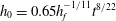
 $Pe$
, the more important the conductive cooling and the larger the cold region is (figure 4).
$Pe$
, the more important the conductive cooling and the larger the cold region is (figure 4).

Figure 3. Snapshots of the flow thermal structure
 $\unicode[STIX]{x1D703}(r,z,t)$
at different times indicated on the plot. Dashed lines represent the thermal boundary layers. Solid grey lines are isotherms for
$\unicode[STIX]{x1D703}(r,z,t)$
at different times indicated on the plot. Dashed lines represent the thermal boundary layers. Solid grey lines are isotherms for
 $\unicode[STIX]{x1D703}=0.2$
,
$\unicode[STIX]{x1D703}=0.2$
,
 $0.4$
,
$0.4$
,
 $0.6$
and
$0.6$
and
 $0.8$
. Here, the temperature field is decoupled from the dynamics, i.e.
$0.8$
. Here, the temperature field is decoupled from the dynamics, i.e.
 $\unicode[STIX]{x1D708}=1$
and
$\unicode[STIX]{x1D708}=1$
and
 $Pe=100$
.
$Pe=100$
.

Figure 4. Snapshots of the flow thermal structure
 $\unicode[STIX]{x1D703}(r,z,t)$
for different set (
$\unicode[STIX]{x1D703}(r,z,t)$
for different set (
 $\unicode[STIX]{x1D708}$
,
$\unicode[STIX]{x1D708}$
,
 $Pe$
) with
$Pe$
) with
 $\unicode[STIX]{x1D708}=1$
,
$\unicode[STIX]{x1D708}=1$
,
 $0.1$
,
$0.1$
,
 $0.01$
and
$0.01$
and
 $0.001$
and
$0.001$
and
 $Pe=1$
,
$Pe=1$
,
 $10$
,
$10$
,
 $100$
and
$100$
and
 $1000$
at
$1000$
at
 $t=10$
. While
$t=10$
. While
 $Pe$
controls the thermal structure of the flow, it has only a small influence on the flow aspect ratio which is controlled by
$Pe$
controls the thermal structure of the flow, it has only a small influence on the flow aspect ratio which is controlled by
 $\unicode[STIX]{x1D708}$
.
$\unicode[STIX]{x1D708}$
.

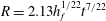
Figure 5. (a) Thickness normalized by the thickness at the centre
 $h(r,t)/h_{0}(t)$
versus radial axis normalized by the current radius
$h(r,t)/h_{0}(t)$
versus radial axis normalized by the current radius
 $r/R(t)$
at different times indicated on the plot for
$r/R(t)$
at different times indicated on the plot for
 $Pe=1.0$
and
$Pe=1.0$
and
 $\unicode[STIX]{x1D708}=1.0$
. The solid lines represent the thickness profiles and the dashed lines represent the thermal boundary layers. The predicted morphology (2.50) (dotted line) is also plotted for comparison. (b) Same plot but for
$\unicode[STIX]{x1D708}=1.0$
. The solid lines represent the thickness profiles and the dashed lines represent the thermal boundary layers. The predicted morphology (2.50) (dotted line) is also plotted for comparison. (b) Same plot but for
 $\unicode[STIX]{x1D708}=10^{-3}$
.
$\unicode[STIX]{x1D708}=10^{-3}$
.
3.1.2 Thickness and temperature profile, effect of
$\unicode[STIX]{x1D708}$

When accounting for the temperature dependence of the viscosity, the region of cold fluid at the tip is marked by a higher viscosity which enhances flow thickening at the expense of spreading. The larger the viscosity contrast, the larger the aspect ratio
 $h_{0}/R$
(figure 4). For instance, for the same value of
$h_{0}/R$
(figure 4). For instance, for the same value of
 $Pe=1$
, while the aspect ratio is
$Pe=1$
, while the aspect ratio is
 $0.7$
for
$0.7$
for
 $\unicode[STIX]{x1D708}=1$
at
$\unicode[STIX]{x1D708}=1$
at
 $t=10$
, it is
$t=10$
, it is
 $4.2$
at the same time for
$4.2$
at the same time for
 $\unicode[STIX]{x1D708}=10^{-3}$
(figure 4). Nevertheless, the shape of the flow remains essentially self-similar, i.e. well described by (2.50) and cannot be differentiated from the shape of an isoviscous current if the thickness and the radial coordinates are rescaled by the thickness at the centre
$\unicode[STIX]{x1D708}=10^{-3}$
(figure 4). Nevertheless, the shape of the flow remains essentially self-similar, i.e. well described by (2.50) and cannot be differentiated from the shape of an isoviscous current if the thickness and the radial coordinates are rescaled by the thickness at the centre
 $h_{0}(t)$
and radius
$h_{0}(t)$
and radius
 $R(t)$
(figure 5).
$R(t)$
(figure 5).
While the flow thermal structure is similar to the isoviscous case (figure 4), the important thickening induced by the viscosity increase tends to limit heat loss to the surrounding and to increase the size of the thermal anomaly at a given time. For instance, for
 $Pe=1$
at
$Pe=1$
at
 $t=10$
, while the thermal anomaly extends over approximately
$t=10$
, while the thermal anomaly extends over approximately
 $30\,\%$
of the flow for
$30\,\%$
of the flow for
 $\unicode[STIX]{x1D708}=1$
, it extends over more than
$\unicode[STIX]{x1D708}=1$
, it extends over more than
 $50\,\%$
for
$50\,\%$
for
 $\unicode[STIX]{x1D708}=10^{-3}$
(figure 4).
$\unicode[STIX]{x1D708}=10^{-3}$
(figure 4).
As expected, a larger Péclet number leads to a larger thermal anomaly (figure 4). However, although different Péclet numbers cause very different thermal structures, the influence of the Péclet number on the flow morphology is small, much smaller than the effect of the viscosity contrast
 $\unicode[STIX]{x1D708}$
(figure 4). For instance, at
$\unicode[STIX]{x1D708}$
(figure 4). For instance, at
 $t=10$
for
$t=10$
for
 $\unicode[STIX]{x1D708}=10^{-3}$
, the thermal anomaly is still attached to the tip of the current for
$\unicode[STIX]{x1D708}=10^{-3}$
, the thermal anomaly is still attached to the tip of the current for
 $Pe=1000$
whereas it makes approximately
$Pe=1000$
whereas it makes approximately
 $50\,\%$
of the current for
$50\,\%$
of the current for
 $Pe=1$
; but, the thickness
$Pe=1$
; but, the thickness
 $h_{0}$
and the radius
$h_{0}$
and the radius
 $R$
in both cases differ only by a few per cent (figure 4). This confirms that, in this regime, the spreading of the flow is not controlled by the mean temperature or average viscosity of the flow, but by the local dynamics at the flow front, as suggested by Lister et al. (Reference Lister, Peng and Neufeld2013).
$R$
in both cases differ only by a few per cent (figure 4). This confirms that, in this regime, the spreading of the flow is not controlled by the mean temperature or average viscosity of the flow, but by the local dynamics at the flow front, as suggested by Lister et al. (Reference Lister, Peng and Neufeld2013).
3.2 Quantitative description
3.2.1 Evolution of the thickness and the radius
In this bending dominated regime, the dynamics shows three different spreading phases. The thickness as well as the radius first evolve like an isoviscous flow, i.e.
 $h_{0}\propto t^{8/22}$
(2.52) and
$h_{0}\propto t^{8/22}$
(2.52) and
 $R\propto t^{7/22}$
(2.53) (figure 6). In a second phase, thickening occurs at the expense of spreading and the dynamics deviates from the isoviscous case. Finally, the current returns to an isoviscous-like dynamics but offset from the hot isoviscous scaling law by a factor that depends on the viscosity contrast (figure 6).
$R\propto t^{7/22}$
(2.53) (figure 6). In a second phase, thickening occurs at the expense of spreading and the dynamics deviates from the isoviscous case. Finally, the current returns to an isoviscous-like dynamics but offset from the hot isoviscous scaling law by a factor that depends on the viscosity contrast (figure 6).

Figure 6. (a) Dimensionless thickness at the centre
 $h_{0}$
versus dimensionless time
$h_{0}$
versus dimensionless time
 $t$
for different sets
$t$
for different sets
 $(\unicode[STIX]{x1D708},Pe)$
indicated on the plot. Dotted lines: scaling laws
$(\unicode[STIX]{x1D708},Pe)$
indicated on the plot. Dotted lines: scaling laws
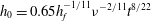 $h_{0}=0.65h_{f}^{-1/11}\unicode[STIX]{x1D708}^{-2/11}t^{8/22}$
for
$h_{0}=0.65h_{f}^{-1/11}\unicode[STIX]{x1D708}^{-2/11}t^{8/22}$
for
 $\unicode[STIX]{x1D708}=1.0$
and
$\unicode[STIX]{x1D708}=1.0$
and
 $0.01$
. (b) Dimensionless radius
$0.01$
. (b) Dimensionless radius
 $R$
versus dimensionless time
$R$
versus dimensionless time
 $t$
for the same sets
$t$
for the same sets
 $(\unicode[STIX]{x1D708},Pe)$
. Dotted lines: scaling laws
$(\unicode[STIX]{x1D708},Pe)$
. Dotted lines: scaling laws
 $R=2.13h_{f}^{1/22}\unicode[STIX]{x1D708}^{1/11}t^{7/22}$
for
$R=2.13h_{f}^{1/22}\unicode[STIX]{x1D708}^{1/11}t^{7/22}$
for
 $\unicode[STIX]{x1D708}=1.0$
and
$\unicode[STIX]{x1D708}=1.0$
and
 $0.01$
. (c) Dimensionless effective viscosity versus dimensionless time
$0.01$
. (c) Dimensionless effective viscosity versus dimensionless time
 $t$
for different
$t$
for different
 $Pe$
and
$Pe$
and
 $\unicode[STIX]{x1D708}=0.01$
. Solid lines: dimensionless effective viscosity
$\unicode[STIX]{x1D708}=0.01$
. Solid lines: dimensionless effective viscosity
 $\unicode[STIX]{x1D702}_{e}$
defined by (3.3). Dotted lines: dimensionless average flow viscosity defined by
$\unicode[STIX]{x1D702}_{e}$
defined by (3.3). Dotted lines: dimensionless average flow viscosity defined by
 $\overline{\unicode[STIX]{x1D702}_{a}(t)}=(1/V(t))\int _{0}^{R(t)}\int _{0}^{h(r,t)}r\unicode[STIX]{x1D702}(\unicode[STIX]{x1D703})\,\text{d}r\,\text{d}z$
where
$\overline{\unicode[STIX]{x1D702}_{a}(t)}=(1/V(t))\int _{0}^{R(t)}\int _{0}^{h(r,t)}r\unicode[STIX]{x1D702}(\unicode[STIX]{x1D703})\,\text{d}r\,\text{d}z$
where
 $V(t)$
is the current volume. Dashed lines: dimensionless average front viscosity
$V(t)$
is the current volume. Dashed lines: dimensionless average front viscosity
 $\unicode[STIX]{x1D702}_{f}$
defined by (3.4).
$\unicode[STIX]{x1D702}_{f}$
defined by (3.4).
These different propagation phases thus reflect variations in the spreading rate of the current. As described in § 2.7, the propagation speed of the front is governed by local conditions in the peeling region and is given in dimensional form by (2.51); it decreases when the viscosity
 $\unicode[STIX]{x1D702}$
increases.
$\unicode[STIX]{x1D702}$
increases.
Inserting the cold viscosity
 $\unicode[STIX]{x1D702}_{c}$
in place of
$\unicode[STIX]{x1D702}_{c}$
in place of
 $\unicode[STIX]{x1D702}$
into (2.51), we find that the dimensionless thickness and radius for a cold isoviscous current evolve as
$\unicode[STIX]{x1D702}$
into (2.51), we find that the dimensionless thickness and radius for a cold isoviscous current evolve as
 $$\begin{eqnarray}\displaystyle & \displaystyle h_{0}=0.65\unicode[STIX]{x1D708}^{-2/11}h_{f}^{-1/11}t^{8/22}, & \displaystyle\end{eqnarray}$$
 $$\begin{eqnarray}\displaystyle & \displaystyle R=2.13\unicode[STIX]{x1D708}^{1/11}h_{f}^{1/22}t^{7/22}. & \displaystyle\end{eqnarray}$$
3.2.2 Flow effective viscosity
The effective viscosity of the current, i.e. the dimensionless viscosity
 $\unicode[STIX]{x1D702}_{e}$
which controls the current spreading rate in (2.51), is obtained by substituting
$\unicode[STIX]{x1D702}_{e}$
which controls the current spreading rate in (2.51), is obtained by substituting
 $\unicode[STIX]{x1D708}$
by
$\unicode[STIX]{x1D708}$
by
 $1/\unicode[STIX]{x1D702}_{e}(t)$
in (3.1) and reads
$1/\unicode[STIX]{x1D702}_{e}(t)$
in (3.1) and reads
 $$\begin{eqnarray}\displaystyle \unicode[STIX]{x1D702}_{e}(t)=\left(\frac{h_{0}(t)t^{-8/22}}{0.65h_{f}^{-1/11}}\right)^{11/2}, & & \displaystyle\end{eqnarray}$$
where
 $h_{0}(t)$
is given by our simulations.
$h_{0}(t)$
is given by our simulations.
As suggested by the results of § 3.2.1, the effective viscosity is first low (figure 6
c). It rapidly increases in the second phase of propagation and finally tends to the cold viscosity
 $1/\unicode[STIX]{x1D708}$
in the third phase. The effective viscosity is however much larger than the average flow viscosity (figure 6
c).
$1/\unicode[STIX]{x1D708}$
in the third phase. The effective viscosity is however much larger than the average flow viscosity (figure 6
c).
We calculate the average viscosity
 $\unicode[STIX]{x1D702}_{f}(t)$
over a front region of size
$\unicode[STIX]{x1D702}_{f}(t)$
over a front region of size
 $L$
in between
$L$
in between
 $R(t)-L$
and
$R(t)-L$
and
 $R(t)$
 $$\begin{eqnarray}\displaystyle \unicode[STIX]{x1D702}_{f}=\frac{1}{V_{f}}\int _{R-L}^{R}\int _{0}^{h}r\unicode[STIX]{x1D702}(\unicode[STIX]{x1D703})\,\text{d}r\,\text{d}z, & & \displaystyle\end{eqnarray}$$
where
 $V_{f}(t)$
is the volume of this region. The numerical evaluation of
$V_{f}(t)$
is the volume of this region. The numerical evaluation of
 $\unicode[STIX]{x1D702}_{f}(t)$
for
$\unicode[STIX]{x1D702}_{f}(t)$
for
 $L=4L_{p}(t)$
, where
$L=4L_{p}(t)$
, where
 $L_{p}$
is the peeling length scale defined by Lister et al. (Reference Lister, Peng and Neufeld2013), given by
$L_{p}$
is the peeling length scale defined by Lister et al. (Reference Lister, Peng and Neufeld2013), given by
 $$\begin{eqnarray}\displaystyle L_{p}=1.08h_{f}^{13/22}\unicode[STIX]{x1D702}_{e}^{-2/11}t^{3/22}, & & \displaystyle\end{eqnarray}$$
fits relatively well the behaviour of the effective viscosity
 $\unicode[STIX]{x1D702}_{e}$
(figure 6
c).
$\unicode[STIX]{x1D702}_{e}$
(figure 6
c).
Therefore, the effective viscosity, and thus the spreading rate, are controlled by the average viscosity of a small region at the front of size
 $L=O(L_{p})$
. Note that in the first flow phase, the effective viscosity
$L=O(L_{p})$
. Note that in the first flow phase, the effective viscosity
 $\unicode[STIX]{x1D702}_{e}$
, and thus the average viscosity of the peeling region, is larger than
$\unicode[STIX]{x1D702}_{e}$
, and thus the average viscosity of the peeling region, is larger than
 $1$
as the current has to accommodate the cold fluid initially present in the prewetting film. The effective viscosity is initially equal to 1 in the case of an initially hot prewetting film (see appendix C).
$1$
as the current has to accommodate the cold fluid initially present in the prewetting film. The effective viscosity is initially equal to 1 in the case of an initially hot prewetting film (see appendix C).
Average local thermal conditions in the peeling region thus control the spreading rate in the bending regime.
3.2.3 Evolution of the thermal condition at the tip
The thermal anomaly is first advected at the same velocity as the current itself, i.e.
 $R(t)=R_{c}(t)$
(figure 7
a). After a time that depends on
$R(t)=R_{c}(t)$
(figure 7
a). After a time that depends on
 $Pe$
and
$Pe$
and
 $\unicode[STIX]{x1D708}$
, the flow front leaves the thermal anomaly behind and
$\unicode[STIX]{x1D708}$
, the flow front leaves the thermal anomaly behind and
 $R(t)-R_{c}(t)$
increases with time (figure 7).
$R(t)-R_{c}(t)$
increases with time (figure 7).

Figure 7. (a) Extent of the cold fluid region
 $R(t)-R_{c}(t)$
versus dimensionless time for different combinations (
$R(t)-R_{c}(t)$
versus dimensionless time for different combinations (
 $\unicode[STIX]{x1D708}$
,
$\unicode[STIX]{x1D708}$
,
 $Pe$
) indicated on the plot. (b) Same plot but where we rescale the extent of the cold fluid region by
$Pe$
) indicated on the plot. (b) Same plot but where we rescale the extent of the cold fluid region by
 $Pe^{-1/3}\unicode[STIX]{x1D708}^{7/33}$
. Dotted line: scaling law
$Pe^{-1/3}\unicode[STIX]{x1D708}^{7/33}$
. Dotted line: scaling law
 $(R(t)-R_{c}(t))Pe^{1/3}\unicode[STIX]{x1D708}^{-7/33}=2.1h_{f}^{7/66}t^{9/22}$
.
$(R(t)-R_{c}(t))Pe^{1/3}\unicode[STIX]{x1D708}^{-7/33}=2.1h_{f}^{7/66}t^{9/22}$
.
In the bending regime, the interior pressure is constant and the thickness profile
 $h(r,t)$
is given by (2.50) (figure 5). The radius of the thermal anomaly
$h(r,t)$
is given by (2.50) (figure 5). The radius of the thermal anomaly
 $R_{c}(t)$
is theoretically taken as corresponding to the radius in the flow where heat advection locally balances heat loss, i.e.
$R_{c}(t)$
is theoretically taken as corresponding to the radius in the flow where heat advection locally balances heat loss, i.e.
 $$\begin{eqnarray}\displaystyle \frac{\text{d}}{\text{d}t}(\unicode[STIX]{x1D6E9}_{b}h)\sim Pe^{-1}\frac{\unicode[STIX]{x1D6E9}_{b}}{h}. & & \displaystyle\end{eqnarray}$$
Using the thickness profile (2.50), (3.6) becomes
 $$\begin{eqnarray}\displaystyle \unicode[STIX]{x1D6FC}^{2}\left(1+\frac{R_{c}}{R}\right)^{2}\left(\unicode[STIX]{x1D6E9}_{b}\frac{\text{d}h_{0}}{\text{d}t}+h_{0}\frac{\text{d}\unicode[STIX]{x1D6E9}_{b}}{\text{d}t}\right)+\frac{4h_{0}R_{c}^{2}\unicode[STIX]{x1D6E9}_{b}}{R^{3}}\frac{\text{d}R}{\text{d}t}\unicode[STIX]{x1D6FC}\left(1+\frac{R_{c}}{R}\right)\sim \frac{Pe^{-1}\unicode[STIX]{x1D6E9}_{b}}{\displaystyle \unicode[STIX]{x1D6FC}^{2}\left(1+\frac{R_{c}}{R}\right)^{2}h_{0}}, & & \displaystyle \nonumber\\ \displaystyle & & \displaystyle\end{eqnarray}$$
where
 $\unicode[STIX]{x1D6FC}(t)=(R(t)-R_{c}(t))/R(t)$
is the normalized region beyond
$\unicode[STIX]{x1D6FC}(t)=(R(t)-R_{c}(t))/R(t)$
is the normalized region beyond
 $r=R_{c}(t)$
. In the limit
$r=R_{c}(t)$
. In the limit
 $\unicode[STIX]{x1D6FC}\ll 1$
, i.e.
$\unicode[STIX]{x1D6FC}\ll 1$
, i.e.
 $R_{c}/R\sim 1$
, the time derivative is locally dominated by its advective part (
$R_{c}/R\sim 1$
, the time derivative is locally dominated by its advective part (
 $\propto \unicode[STIX]{x1D6FC}$
) and we finally get
$\propto \unicode[STIX]{x1D6FC}$
) and we finally get
 $$\begin{eqnarray}\displaystyle \unicode[STIX]{x1D6FC}^{3}\sim \frac{Pe^{-1}}{h_{0}^{2}(t)}\frac{R}{\displaystyle \frac{\unicode[STIX]{x2202}R}{\unicode[STIX]{x2202}t}}. & & \displaystyle\end{eqnarray}$$
Substituting
 $h_{0}(t)$
and
$h_{0}(t)$
and
 $R(t)$
by their respective scaling laws (3.1) and (3.2), the size evolution of the normalized cold front region
$R(t)$
by their respective scaling laws (3.1) and (3.2), the size evolution of the normalized cold front region
 $\unicode[STIX]{x1D6FC}$
reads
$\unicode[STIX]{x1D6FC}$
reads
 $$\begin{eqnarray}\displaystyle \unicode[STIX]{x1D6FC}(t)\sim Pe^{-1/3}\unicode[STIX]{x1D708}^{4/33}h_{f}^{2/33}t^{1/11}, & & \displaystyle\end{eqnarray}$$
which is equivalent to
 $$\begin{eqnarray}\displaystyle R(t)-R_{c}(t)\sim Pe^{-1/3}\unicode[STIX]{x1D708}^{7/33}h_{f}^{7/66}t^{9/22}. & & \displaystyle\end{eqnarray}$$
The predicted scaling law for the evolution of the cold fluid region (3.10) closely fits the numerical simulations for
 $\unicode[STIX]{x1D708}<1$
and for different Péclet numbers (figure 7). In particular, this scaling perfectly fits the simulations with a numerical prefactor equal to
$\unicode[STIX]{x1D708}<1$
and for different Péclet numbers (figure 7). In particular, this scaling perfectly fits the simulations with a numerical prefactor equal to
 $2.1$
.
$2.1$
.
3.2.4 Summary of the bending regime dynamics
The spreading rate of the current is controlled by the average viscosity in the peeling region which depends on the average local thermal conditions at the tip.
At the initiation of the flow, heat advection is larger than conductive heat losses in the peeling region, the thermal anomaly reaches the flow front and the spreading rate is similar to the one of an isoviscous hot current.
Once heat loss in the peeling region becomes larger than heat advection, the current tip leaves the thermal anomaly behind. The average temperature of the peeling region decreases and the effective viscosity rapidly increases. Setting
 $(R-R_{c})(t)$
(3.10) equal to the peeling length scale
$(R-R_{c})(t)$
(3.10) equal to the peeling length scale
 $L_{p}(t)$
(3.5), taking
$L_{p}(t)$
(3.5), taking
 $\unicode[STIX]{x1D708}=1$
and inverting for time, we found that the time
$\unicode[STIX]{x1D708}=1$
and inverting for time, we found that the time
 $t_{b2}$
to reach the second thermal phase reads
$t_{b2}$
to reach the second thermal phase reads
 $$\begin{eqnarray}\displaystyle t_{b2}=7\times 10^{-3}Pe^{11/9}h_{f}^{16/9}, & & \displaystyle\end{eqnarray}$$
where the numerical prefactor is chosen from the numerical solutions. When rescaling the time of the simulations by
 $t_{b2}$
, the different simulations enter the second phase simultaneously (figure 8
a).
$t_{b2}$
, the different simulations enter the second phase simultaneously (figure 8
a).

Figure 8. (a) Dimensionless thickness at the centre
 $h_{0}/h_{0}(t_{b2})$
versus dimensionless time
$h_{0}/h_{0}(t_{b2})$
versus dimensionless time
 $t/t_{b2}$
, where
$t/t_{b2}$
, where
 $t_{b2}$
is the time to enter the second thermal phase of the bending regime (3.11), for different sets
$t_{b2}$
is the time to enter the second thermal phase of the bending regime (3.11), for different sets
 $(\unicode[STIX]{x1D708},Pe)$
indicated on the plot. Dotted line: scaling laws
$(\unicode[STIX]{x1D708},Pe)$
indicated on the plot. Dotted line: scaling laws
 $h_{0}(t)/h_{0}(t_{b2})=(t/t_{b2})^{8/22}$
. (b) Dimensionless thickness at the centre
$h_{0}(t)/h_{0}(t_{b2})=(t/t_{b2})^{8/22}$
. (b) Dimensionless thickness at the centre
 $h_{0}/h_{0}(t_{b3})$
versus dimensionless time
$h_{0}/h_{0}(t_{b3})$
versus dimensionless time
 $t/t_{b3}$
, where
$t/t_{b3}$
, where
 $t_{b3}$
is the time to enter the third thermal phase of the bending regime (3.12), for different sets
$t_{b3}$
is the time to enter the third thermal phase of the bending regime (3.12), for different sets
 $(\unicode[STIX]{x1D708},Pe)$
indicated on the plot. Dotted line: scaling laws
$(\unicode[STIX]{x1D708},Pe)$
indicated on the plot. Dotted line: scaling laws
 $h_{0}(t)/h_{0}(t_{b3})=(t/t_{b3})^{8/22}$
.
$h_{0}(t)/h_{0}(t_{b3})=(t/t_{b3})^{8/22}$
.
Finally, when the peeling region becomes entirely cold, i.e.
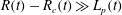 $R(t)-R_{c}(t)\gg L_{p}(t)$
, the flow behaves as an isoviscous cold current. Repeating the same exercise as before while keeping the viscosity contrast
$R(t)-R_{c}(t)\gg L_{p}(t)$
, the flow behaves as an isoviscous cold current. Repeating the same exercise as before while keeping the viscosity contrast
 $\unicode[STIX]{x1D708}$
, we found that the time
$\unicode[STIX]{x1D708}$
, we found that the time
 $t_{b3}$
for the flow to enter this third phase reads
$t_{b3}$
for the flow to enter this third phase reads
 $$\begin{eqnarray}\displaystyle t_{b3}=14Pe^{11/9}h_{f}^{16/9}\unicode[STIX]{x1D708}^{-1/9}, & & \displaystyle\end{eqnarray}$$
where the numerical prefactor is chosen from the numerical solutions. When rescaling the time of the simulations by
 $t_{b3}$
, the different simulations enter the third phase simultaneously (figure 8
b).
$t_{b3}$
, the different simulations enter the third phase simultaneously (figure 8
b).
4 Evolution in the gravity current regime
To study the late time behaviour, we concentrate on the case where only the weight of the fluid contributes to the pressure. We numerically solve and study the system composed by (2.39) and (2.40) where we remove the bending contribution in the pressure
 $P$
, i.e.
$P$
, i.e.
 $P=h$
. We follow the same framework as in § 3.
$P=h$
. We follow the same framework as in § 3.
4.1 Qualitative description
4.1.1 Thermal structure for an isoviscous flow, effect of
$Pe$

As in the bending regime, the bulk of the fluid first expands at the injection temperature and
 $R_{c}(t)=R(t)$
. As the bottom and top cool by conduction, thermal boundary layers form at the contact with the surrounding medium and connect at the tip of the current. However, in the gravity current regime, for a constant viscosity, the thickness of the current tends to a constant. Therefore, when conduction in the surrounding medium balances the input of heat at the centre and the flow front has already left the thermal anomaly behind, its extent approaches a steady state (figure 9).
$R_{c}(t)=R(t)$
. As the bottom and top cool by conduction, thermal boundary layers form at the contact with the surrounding medium and connect at the tip of the current. However, in the gravity current regime, for a constant viscosity, the thickness of the current tends to a constant. Therefore, when conduction in the surrounding medium balances the input of heat at the centre and the flow front has already left the thermal anomaly behind, its extent approaches a steady state (figure 9).

Figure 9. Snapshots of the flow thermal structure
 $\unicode[STIX]{x1D703}(r,z,t)$
at different times indicated on the plot. Dashed lines: thermal boundary layers. Here,
$\unicode[STIX]{x1D703}(r,z,t)$
at different times indicated on the plot. Dashed lines: thermal boundary layers. Here,
 $\unicode[STIX]{x1D708}=1$
and
$\unicode[STIX]{x1D708}=1$
and
 $Pe=100$
.
$Pe=100$
.
The radius of the steady-state thermal anomaly
 $R_{c}$
also largely depends on
$R_{c}$
also largely depends on
 $Pe$
in this regime: the larger the number
$Pe$
in this regime: the larger the number
 $Pe$
, the larger the radius
$Pe$
, the larger the radius
 $R_{c}$
(figure 10).
$R_{c}$
(figure 10).

Figure 10. Snapshots of the flow thermal structure
 $\unicode[STIX]{x1D703}(r,z,t)$
for different sets (
$\unicode[STIX]{x1D703}(r,z,t)$
for different sets (
 $\unicode[STIX]{x1D708}$
,
$\unicode[STIX]{x1D708}$
,
 $Pe$
) with
$Pe$
) with
 $\unicode[STIX]{x1D708}=1$
,
$\unicode[STIX]{x1D708}=1$
,
 $0.1$
,
$0.1$
,
 $0.01$
and
$0.01$
and
 $0.001$
and
$0.001$
and
 $Pe=1$
,
$Pe=1$
,
 $10$
,
$10$
,
 $100$
and
$100$
and
 $1000$
at
$1000$
at
 $t=200$
.
$t=200$
.
4.1.2 Thickness and temperature profile, effect of
$\unicode[STIX]{x1D708}$

For a current with a viscosity that depends on temperature, as soon as the cooling becomes more effective and the thermal anomaly detaches from the current tip, the spreading slows down and flow thickening is enhanced (figure 10). For instance, for
 $Pe=1$
, while the aspect ratio
$Pe=1$
, while the aspect ratio
 $h_{0}/R$
is approximately
$h_{0}/R$
is approximately
 $0.12$
for
$0.12$
for
 $\unicode[STIX]{x1D708}=1$
at
$\unicode[STIX]{x1D708}=1$
at
 $t=200$
, it is
$t=200$
, it is
 ${\sim}1$
for
${\sim}1$
for
 $\unicode[STIX]{x1D708}=10^{-3}$
(figure 10). The shape of the current is not self-similar and the front steepens when the viscosity increases in comparison to the isoviscous case as noted by Bercovici (Reference Bercovici1994). However, when the current becomes much larger than the thermal anomaly, the current side slumps to become less steep (figure 10) and recovers a shape similar to an isoviscous flow with a cold viscosity.
$\unicode[STIX]{x1D708}=10^{-3}$
(figure 10). The shape of the current is not self-similar and the front steepens when the viscosity increases in comparison to the isoviscous case as noted by Bercovici (Reference Bercovici1994). However, when the current becomes much larger than the thermal anomaly, the current side slumps to become less steep (figure 10) and recovers a shape similar to an isoviscous flow with a cold viscosity.
The thermal structure is similar to the isoviscous case (
 $\unicode[STIX]{x1D708}=1$
). In particular, after a time that depends on
$\unicode[STIX]{x1D708}=1$
). In particular, after a time that depends on
 $Pe$
, the thermal anomaly approaches a steady-state profile (figure 10). As in the bending regime, the thickening at the centre limits heat loss to the surrounding for large values of the viscosity contrast
$Pe$
, the thermal anomaly approaches a steady-state profile (figure 10). As in the bending regime, the thickening at the centre limits heat loss to the surrounding for large values of the viscosity contrast
 $\unicode[STIX]{x1D708}$
. Therefore, the extent of the thermal anomaly in the steady state is slightly larger for a larger viscosity contrast. For instance, for
$\unicode[STIX]{x1D708}$
. Therefore, the extent of the thermal anomaly in the steady state is slightly larger for a larger viscosity contrast. For instance, for
 $Pe=10$
at
$Pe=10$
at
 $t=200$
, while the thermal anomaly extends over less than
$t=200$
, while the thermal anomaly extends over less than
 $2$
for
$2$
for
 $\unicode[STIX]{x1D708}=1$
, it reaches
$\unicode[STIX]{x1D708}=1$
, it reaches
 ${\sim}3$
for
${\sim}3$
for
 $\unicode[STIX]{x1D708}=10^{-3}$
.
$\unicode[STIX]{x1D708}=10^{-3}$
.
The flow morphology is much more sensitive to
 $Pe$
in the gravity current regime than in the bending regime and different
$Pe$
in the gravity current regime than in the bending regime and different
 $Pe$
lead to different current morphologies for a given
$Pe$
lead to different current morphologies for a given
 $\unicode[STIX]{x1D708}$
(figure 10). For instance, for
$\unicode[STIX]{x1D708}$
(figure 10). For instance, for
 $\unicode[STIX]{x1D708}=10^{-3}$
at
$\unicode[STIX]{x1D708}=10^{-3}$
at
 $t=200$
, the thermal anomaly is still attached to the tip for
$t=200$
, the thermal anomaly is still attached to the tip for
 $Pe=10^{3}$
and the aspect ratio of the flow
$Pe=10^{3}$
and the aspect ratio of the flow
 $h_{0}/R$
is close to
$h_{0}/R$
is close to
 $0.15$
. In contrast, for
$0.15$
. In contrast, for
 $Pe=1$
, the thermal anomaly radius is less than
$Pe=1$
, the thermal anomaly radius is less than
 $30\,\%$
of the current radius and the dimensionless aspect ratio of the flow is much larger
$30\,\%$
of the current radius and the dimensionless aspect ratio of the flow is much larger
 $h_{0}/R=1.15$
(figure 10).
$h_{0}/R=1.15$
(figure 10).
4.2 Quantitative description
4.2.1 Evolution of the thickness and radius
As in the bending regime, the dynamics in the gravity current regime shows three different spreading phases. The thickness as well as the radius first follow the isoviscous scaling laws for a given hot viscosity
 $\unicode[STIX]{x1D702}_{h}$
, i.e.
$\unicode[STIX]{x1D702}_{h}$
, i.e.
 $h_{0}$
approaches a constant and
$h_{0}$
approaches a constant and
 $R\propto t^{1/2}$
(figure 11). In a second phase, the thickness rapidly increases and the spreading slows down. Finally, the current returns to an isoviscous-like dynamics but offset from the hot isoviscous scaling law by a factor that depends on the viscosity contrast (figure 11). In particular, replacing
$R\propto t^{1/2}$
(figure 11). In a second phase, the thickness rapidly increases and the spreading slows down. Finally, the current returns to an isoviscous-like dynamics but offset from the hot isoviscous scaling law by a factor that depends on the viscosity contrast (figure 11). In particular, replacing
 $\unicode[STIX]{x1D702}$
by
$\unicode[STIX]{x1D702}$
by
 $\unicode[STIX]{x1D702}_{c}$
instead of
$\unicode[STIX]{x1D702}_{c}$
instead of
 $\unicode[STIX]{x1D702}_{h}$
in (2.54), we find that the dimensionless radius
$\unicode[STIX]{x1D702}_{h}$
in (2.54), we find that the dimensionless radius
 $R(t)$
in the third flow phase matches the one of a cold viscosity current (4.1) (figure 11)
$R(t)$
in the third flow phase matches the one of a cold viscosity current (4.1) (figure 11)
 $$\begin{eqnarray}\displaystyle R(t)=1.10\unicode[STIX]{x1D708}^{1/8}t^{1/2}. & & \displaystyle\end{eqnarray}$$
As in the bending regime, these spreading rate variations reflect variations in the flow effective viscosity, from the hot to the cold viscosity. However, in that case, the effective viscosity is the average flow viscosity. Using the predicted scaling law for the radius
 $R(t)$
(4.1) as a function of
$R(t)$
(4.1) as a function of
 $\unicode[STIX]{x1D708}_{e}$
to derive the effective viscosity
$\unicode[STIX]{x1D708}_{e}$
to derive the effective viscosity
 $1/\unicode[STIX]{x1D708}_{e}$
, we show that the current average viscosity matches the effective flow viscosity almost perfectly (figure 11
c).
$1/\unicode[STIX]{x1D708}_{e}$
, we show that the current average viscosity matches the effective flow viscosity almost perfectly (figure 11
c).

Figure 11. (a) Dimensionless thickness at the centre
 $h_{0}$
versus dimensionless time
$h_{0}$
versus dimensionless time
 $t$
for different sets
$t$
for different sets
 $(\unicode[STIX]{x1D708},Pe)$
indicated on the plot. Dotted lines represent the scaling laws
$(\unicode[STIX]{x1D708},Pe)$
indicated on the plot. Dotted lines represent the scaling laws
 $h_{0}=2.1\unicode[STIX]{x1D708}^{-1/4}$
for
$h_{0}=2.1\unicode[STIX]{x1D708}^{-1/4}$
for
 $\unicode[STIX]{x1D708}=1.0$
and
$\unicode[STIX]{x1D708}=1.0$
and
 $10^{-2}$
. (b) Dimensionless radius
$10^{-2}$
. (b) Dimensionless radius
 $R$
versus dimensionless time
$R$
versus dimensionless time
 $t$
for the same sets
$t$
for the same sets
 $(\unicode[STIX]{x1D708},Pe)$
. Dotted lines represent the scaling laws
$(\unicode[STIX]{x1D708},Pe)$
. Dotted lines represent the scaling laws
 $R=1.1\unicode[STIX]{x1D708}^{1/8}t^{1/2}$
for
$R=1.1\unicode[STIX]{x1D708}^{1/8}t^{1/2}$
for
 $\unicode[STIX]{x1D708}=1.0$
and
$\unicode[STIX]{x1D708}=1.0$
and
 $10^{-2}$
. (c) Dimensionless effective viscosity versus dimensionless time
$10^{-2}$
. (c) Dimensionless effective viscosity versus dimensionless time
 $t$
for different
$t$
for different
 $Pe$
and
$Pe$
and
 $\unicode[STIX]{x1D708}=0.01$
. Solid lines: effective viscosity
$\unicode[STIX]{x1D708}=0.01$
. Solid lines: effective viscosity
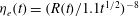 $\unicode[STIX]{x1D702}_{e}(t)=(R(t)/1.1t^{1/2})^{-8}$
. Dashed lines: average flow viscosity defined by
$\unicode[STIX]{x1D702}_{e}(t)=(R(t)/1.1t^{1/2})^{-8}$
. Dashed lines: average flow viscosity defined by
 $\overline{\unicode[STIX]{x1D702}_{a}(t)}=(1/V(t))\int _{0}^{R(t)}\int _{0}^{h(r,t)}r\unicode[STIX]{x1D702}(\unicode[STIX]{x1D703})\,\text{d}r\,\text{d}z$
where
$\overline{\unicode[STIX]{x1D702}_{a}(t)}=(1/V(t))\int _{0}^{R(t)}\int _{0}^{h(r,t)}r\unicode[STIX]{x1D702}(\unicode[STIX]{x1D703})\,\text{d}r\,\text{d}z$
where
 $V(t)$
is the current volume. Note that the irregularities at early times, which are enhanced by the log–log representation, come from a slight decrease of the effective viscosity when the current begins to thickens.
$V(t)$
is the current volume. Note that the irregularities at early times, which are enhanced by the log–log representation, come from a slight decrease of the effective viscosity when the current begins to thickens.
4.2.2 Characterization of the thermal anomaly
The thermal anomaly is first advected at the same velocity as the current itself, i.e.
 $R_{c}(t)/R(t)=1$
(figure 12
a). After a time that depends on
$R_{c}(t)/R(t)=1$
(figure 12
a). After a time that depends on
 $Pe$
and
$Pe$
and
 $\unicode[STIX]{x1D708}$
, the flow front leaves the thermal anomaly behind and the anomaly extent slowly approaches a steady-state profile as the viscosity becomes closer to the cold viscosity (figures 9, 10 and 12).
$\unicode[STIX]{x1D708}$
, the flow front leaves the thermal anomaly behind and the anomaly extent slowly approaches a steady-state profile as the viscosity becomes closer to the cold viscosity (figures 9, 10 and 12).

Figure 12. (a) Normalized thermal anomaly radius
 $R_{c}(t)/R(t)$
versus dimensionless time for different combinations (
$R_{c}(t)/R(t)$
versus dimensionless time for different combinations (
 $\unicode[STIX]{x1D708}$
,
$\unicode[STIX]{x1D708}$
,
 $Pe$
) indicated on the plot. (b) Same plot but where we rescale the normalized thermal anomaly radius
$Pe$
) indicated on the plot. (b) Same plot but where we rescale the normalized thermal anomaly radius
 $R_{c}(t)/R(t)$
by
$R_{c}(t)/R(t)$
by
 $Pe^{1/2}\unicode[STIX]{x1D708}^{-1/4}$
. Dotted line:
$Pe^{1/2}\unicode[STIX]{x1D708}^{-1/4}$
. Dotted line:
 $Pe^{-1/2}\unicode[STIX]{x1D708}^{1/4}R_{c}(t)/R(t)=0.8t^{-1/2}$
.
$Pe^{-1/2}\unicode[STIX]{x1D708}^{1/4}R_{c}(t)/R(t)=0.8t^{-1/2}$
.
At the steady-state radius
 $R_{c}$
of the thermal anomaly, a balance between heat advection and diffusion in the surrounding medium gives
$R_{c}$
of the thermal anomaly, a balance between heat advection and diffusion in the surrounding medium gives
 $$\begin{eqnarray}\displaystyle \unicode[STIX]{x1D6E9}_{b}\frac{U_{0}}{R_{c}}\sim \frac{Pe^{-1}}{h_{0}^{2}}\unicode[STIX]{x1D6E9}_{b}, & & \displaystyle\end{eqnarray}$$
where
 $U_{0}$
is a mean dimensionless velocity of advection. For a gravity current, in contrast to the bending regime, the thickness
$U_{0}$
is a mean dimensionless velocity of advection. For a gravity current, in contrast to the bending regime, the thickness
 $h_{0}$
approaches a constant. Taking
$h_{0}$
approaches a constant. Taking
 $U_{0}$
as a horizontal redistribution of the dimensionless injection rate at
$U_{0}$
as a horizontal redistribution of the dimensionless injection rate at
 $r=R_{c}$
, i.e.
$r=R_{c}$
, i.e.
 $U_{0}=1/(R_{c}h_{0})$
, and using the scaling for the thickness of a cold isoviscous current
$U_{0}=1/(R_{c}h_{0})$
, and using the scaling for the thickness of a cold isoviscous current
 $h_{0}\sim \unicode[STIX]{x1D708}^{-1/4}$
, we obtain
$h_{0}\sim \unicode[STIX]{x1D708}^{-1/4}$
, we obtain
 $$\begin{eqnarray}\displaystyle R_{c}\sim Pe^{1/2}\unicode[STIX]{x1D708}^{-1/8} & & \displaystyle\end{eqnarray}$$
and hence
 $$\begin{eqnarray}\displaystyle \frac{R_{c}}{R(t)}\sim Pe^{1/2}\unicode[STIX]{x1D708}^{-1/4}t^{-1/2}, & & \displaystyle\end{eqnarray}$$
where we have used (4.1).
This scaling law fits our simulation for a prefactor equal to
 $0.8$
(figure 12): when the thermal anomaly enters the steady state, its radius remains constant and the normalized radius
$0.8$
(figure 12): when the thermal anomaly enters the steady state, its radius remains constant and the normalized radius
 $R_{c}(t)/R(t)$
evolves as the inverse of the current radius, i.e. as
$R_{c}(t)/R(t)$
evolves as the inverse of the current radius, i.e. as
 $t^{-1/2}$
(figure 12). Furthermore, both the dependence with
$t^{-1/2}$
(figure 12). Furthermore, both the dependence with
 $Pe$
and
$Pe$
and
 $\unicode[STIX]{x1D708}$
vanish when rescaling
$\unicode[STIX]{x1D708}$
vanish when rescaling
 $R_{c}/R(t)$
by
$R_{c}/R(t)$
by
 $Pe^{1/2}\unicode[STIX]{x1D708}^{-1/4}$
in the steady state (figure 12
b).
$Pe^{1/2}\unicode[STIX]{x1D708}^{-1/4}$
in the steady state (figure 12
b).
4.2.3 Summary of the gravity regime dynamics
In the gravity regime, the current spreading rate is controlled by the flow average viscosity. Therefore, it strongly depends on the extent of the thermal anomaly.
At flow initiation, the thermal anomaly is advected at the same velocity as the current itself and the current spreads with a hot viscosity
 $\unicode[STIX]{x1D702}_{h}$
. Once heat loss over the current balances the heat input at the centre, the current tip leaves the thermal anomaly behind, the average viscosity increases and the spreading rate decreases. The time
$\unicode[STIX]{x1D702}_{h}$
. Once heat loss over the current balances the heat input at the centre, the current tip leaves the thermal anomaly behind, the average viscosity increases and the spreading rate decreases. The time
 $t_{g2}$
to enter this second phase scales with the time to cool the hot current (
$t_{g2}$
to enter this second phase scales with the time to cool the hot current (
 $\unicode[STIX]{x1D708}=1$
) by conduction and reads
$\unicode[STIX]{x1D708}=1$
) by conduction and reads
 $$\begin{eqnarray}\displaystyle t_{g2}=0.65Pe, & & \displaystyle\end{eqnarray}$$
where the numerical prefactor is chosen from the numerical solutions. Indeed, when rescaling the time of the simulations by
 $t_{g2}$
, the different simulations enter the second phase simultaneously (figure 13
a).
$t_{g2}$
, the different simulations enter the second phase simultaneously (figure 13
a).

Figure 13. (a) Dimensionless radius at the centre
 $R/R(t_{g2})$
versus dimensionless time
$R/R(t_{g2})$
versus dimensionless time
 $t/t_{g2}$
, where
$t/t_{g2}$
, where
 $t_{g2}$
(4.5) is the time to enter the second thermal phase of the gravity regime, for different sets of
$t_{g2}$
(4.5) is the time to enter the second thermal phase of the gravity regime, for different sets of
 $(\unicode[STIX]{x1D708},Pe)$
indicated on the plot. Dotted line: scaling law
$(\unicode[STIX]{x1D708},Pe)$
indicated on the plot. Dotted line: scaling law
 $R/R(t_{g2})=(t/t_{g2})^{1/2}$
. (b) Dimensionless radius
$R/R(t_{g2})=(t/t_{g2})^{1/2}$
. (b) Dimensionless radius
 $R/R(t_{g3})$
versus dimensionless time
$R/R(t_{g3})$
versus dimensionless time
 $t/t_{g3}$
, where
$t/t_{g3}$
, where
 $t_{g3}$
(4.6) is the time to enter the third thermal phase of the gravity regime, for different sets
$t_{g3}$
(4.6) is the time to enter the third thermal phase of the gravity regime, for different sets
 $(\unicode[STIX]{x1D708},Pe)$
indicated on the plot. Dotted line: scaling law
$(\unicode[STIX]{x1D708},Pe)$
indicated on the plot. Dotted line: scaling law
 $R/R(t_{g3})=(t/t_{g3})^{1/2}$
.
$R/R(t_{g3})=(t/t_{g3})^{1/2}$
.
Finally, when the thermal anomaly becomes small compared to the current, i.e.
 $R_{c}/R\ll 1$
, the average flow temperature is close to zero and the current behaves as an isoviscous cold current. The time
$R_{c}/R\ll 1$
, the average flow temperature is close to zero and the current behaves as an isoviscous cold current. The time
 $t_{g3}$
to enter this third phase scales as the time to cool an isoviscous cold gravity current and reads
$t_{g3}$
to enter this third phase scales as the time to cool an isoviscous cold gravity current and reads
 $$\begin{eqnarray}\displaystyle t_{g3}=10Pe\unicode[STIX]{x1D708}^{-1/2}, & & \displaystyle\end{eqnarray}$$
where the numerical prefactor is chosen from the numerical solutions. Indeed, when rescaling the time of the simulations by
 $t_{g3}$
, the different simulations enter the third phase simultaneously (figure 13
b). The time scales
$t_{g3}$
, the different simulations enter the third phase simultaneously (figure 13
b). The time scales
 $t_{g2}$
(respectively
$t_{g2}$
(respectively
 $t_{g3}$
) can be derived by inverting (4.4) for
$t_{g3}$
) can be derived by inverting (4.4) for
 $t$
for a fixed value of
$t$
for a fixed value of
 $R_{c}/R$
and setting
$R_{c}/R$
and setting
 $\unicode[STIX]{x1D708}=1$
(respectively keeping
$\unicode[STIX]{x1D708}=1$
(respectively keeping
 $\unicode[STIX]{x1D708}$
) in a similar way that we derive
$\unicode[STIX]{x1D708}$
) in a similar way that we derive
 $t_{b2}$
(respectively
$t_{b2}$
(respectively
 $t_{b3}$
) in § 3.2.4.
$t_{b3}$
) in § 3.2.4.
5 Different evolutions with bending and gravity
For an isoviscous flow with
 $h_{f}\ll h\ll d_{c}$
, in between the bending and gravity regime, Lister et al. (Reference Lister, Peng and Neufeld2013) also describe a short intermediate regime where the peeling by bending continues to control the propagation but where the flow shows an interior flat-topped region due to the increasing effect of gravity. For simplicity, we only consider the two asymptotic regimes. At the transition, the isoviscous current is characterized by
$h_{f}\ll h\ll d_{c}$
, in between the bending and gravity regime, Lister et al. (Reference Lister, Peng and Neufeld2013) also describe a short intermediate regime where the peeling by bending continues to control the propagation but where the flow shows an interior flat-topped region due to the increasing effect of gravity. For simplicity, we only consider the two asymptotic regimes. At the transition, the isoviscous current is characterized by
 $R\sim 4$
and for
$R\sim 4$
and for
 $h_{f}=0.005$
,
$h_{f}=0.005$
,
 $h_{0}\sim 2$
and
$h_{0}\sim 2$
and
 $t\sim 10$
.
$t\sim 10$
.
For a temperature-dependent viscosity current and for any values of
 $h_{f}$
,
$h_{f}$
,
 $\unicode[STIX]{x1D708}$
and
$\unicode[STIX]{x1D708}$
and
 $Pe$
, the current always transitions to the gravity regime when
$Pe$
, the current always transitions to the gravity regime when
 $R\sim 4$
(figure 14). However, the current thickness as well as the time to reach this transition naturally depends on the bending thermal phase of the current at the transition, i.e. on the combination of (
$R\sim 4$
(figure 14). However, the current thickness as well as the time to reach this transition naturally depends on the bending thermal phase of the current at the transition, i.e. on the combination of (
 $\unicode[STIX]{x1D708}$
,
$\unicode[STIX]{x1D708}$
,
 $Pe$
) considered. For instance, for
$Pe$
) considered. For instance, for
 $\unicode[STIX]{x1D708}=0.01$
and a small value of
$\unicode[STIX]{x1D708}=0.01$
and a small value of
 $Pe=1.0$
, the current transitions to the gravity regime while in the third bending thermal phase. The transition occurs much later and the current is much thicker than for an isoviscous current (
$Pe=1.0$
, the current transitions to the gravity regime while in the third bending thermal phase. The transition occurs much later and the current is much thicker than for an isoviscous current (
 $t_{t}\sim 50$
and
$t_{t}\sim 50$
and
 $h_{0}(t_{t})\sim 8$
, figure 14). In contrast, for
$h_{0}(t_{t})\sim 8$
, figure 14). In contrast, for
 $\unicode[STIX]{x1D708}=0.01$
and a large value of
$\unicode[STIX]{x1D708}=0.01$
and a large value of
 $Pe=10^{5}$
, the current spreads in the first thermal bending phase for a longer period of time; it reaches the transition sooner at a smaller thickness while in the second thermal bending phase, i.e.
$Pe=10^{5}$
, the current spreads in the first thermal bending phase for a longer period of time; it reaches the transition sooner at a smaller thickness while in the second thermal bending phase, i.e.
 $t_{t}\sim 30$
and
$t_{t}\sim 30$
and
 $h_{0}(t_{t})\sim 5$
.
$h_{0}(t_{t})\sim 5$
.

Figure 14. (a) Dimensionless thickness at the centre
 $h_{0}$
versus dimensionless time for different sets
$h_{0}$
versus dimensionless time for different sets
 $(\unicode[STIX]{x1D708},Pe)$
indicated on the plot and an initially hot prewetting film. The grey line represents the isoviscous case
$(\unicode[STIX]{x1D708},Pe)$
indicated on the plot and an initially hot prewetting film. The grey line represents the isoviscous case
 $\unicode[STIX]{x1D708}=1$
. (b) Same plot but for the dimensionless radius
$\unicode[STIX]{x1D708}=1$
. (b) Same plot but for the dimensionless radius
 $R$
. These numerical solutions were obtained by solving (2.39) and (2.40) with the pressure
$R$
. These numerical solutions were obtained by solving (2.39) and (2.40) with the pressure
 $P$
containing both the gravity and the bending contributions.
$P$
containing both the gravity and the bending contributions.
Table 1. Summary of the different transition times.
 $t_{t}$
is the transition time between bending and gravity which is bound by
$t_{t}$
is the transition time between bending and gravity which is bound by
 $t_{t}^{h}$
, when the current transitions in the first bending thermal phase, and
$t_{t}^{h}$
, when the current transitions in the first bending thermal phase, and
 $t_{t}^{c}$
, when the current transitions in the third bending thermal phase.
$t_{t}^{c}$
, when the current transitions in the third bending thermal phase.
 $t_{b2}$
(respectively
$t_{b2}$
(respectively
 $t_{b3}$
) represents the time to transition from phase 1 to phase 2 (respectively from phase 2 to phase 3) in the bending regime.
$t_{b3}$
) represents the time to transition from phase 1 to phase 2 (respectively from phase 2 to phase 3) in the bending regime.
 $t_{g2}$
(respectively
$t_{g2}$
(respectively
 $t_{g3}$
) represents the time to transition from phase 1 to phase 2 (respectively from phase 2 to phase 3) in the gravity regime.
$t_{g3}$
) represents the time to transition from phase 1 to phase 2 (respectively from phase 2 to phase 3) in the gravity regime.

Overall, the time for the current to reach the transition
 $t_{t}$
is the time for its radius to reach
$t_{t}$
is the time for its radius to reach
 $R(t)=4$
. Setting (3.2) equal to
$R(t)=4$
. Setting (3.2) equal to
 $4$
, we obtain
$4$
, we obtain
 $t_{t}=6.5\unicode[STIX]{x1D702}_{e}^{2/7}h_{f}^{-1/7}$
where
$t_{t}=6.5\unicode[STIX]{x1D702}_{e}^{2/7}h_{f}^{-1/7}$
where
 $\unicode[STIX]{x1D702}_{e}$
is the effective viscosity of the current. This transition time depends on the effective viscosity and is bounded by two values
$\unicode[STIX]{x1D702}_{e}$
is the effective viscosity of the current. This transition time depends on the effective viscosity and is bounded by two values
 $t_{t}^{h}<t_{t}<t_{t}^{c}$
. If the current transitions to the gravity regime while in the first thermal bending phase, then
$t_{t}^{h}<t_{t}<t_{t}^{c}$
. If the current transitions to the gravity regime while in the first thermal bending phase, then
 $\unicode[STIX]{x1D702}_{e}\approx 1$
and
$\unicode[STIX]{x1D702}_{e}\approx 1$
and
 $t_{t}^{h}=6.5h_{f}^{-1/7}$
; if the current transitions to the gravity regime while in the third thermal bending phase, then
$t_{t}^{h}=6.5h_{f}^{-1/7}$
; if the current transitions to the gravity regime while in the third thermal bending phase, then
 $\unicode[STIX]{x1D702}_{e}\approx \unicode[STIX]{x1D708}^{-1}$
and
$\unicode[STIX]{x1D702}_{e}\approx \unicode[STIX]{x1D708}^{-1}$
and
 $t_{t}^{c}=6.5\unicode[STIX]{x1D708}^{-2/7}h_{f}^{-1/7}$
(table 1).
$t_{t}^{c}=6.5\unicode[STIX]{x1D708}^{-2/7}h_{f}^{-1/7}$
(table 1).
The subsequent evolution in the gravity regime also depends on the combinations of (
 $\unicode[STIX]{x1D708}$
,
$\unicode[STIX]{x1D708}$
,
 $Pe$
) considered. Indeed, in contrast to the bending regime where the effective viscosity is that of a small region at the tip, the effective viscosity is the average flow viscosity in the gravity regime. Therefore, the flow effective viscosity can drastically decrease when entering the gravity regime. In particular, a current in the
$Pe$
) considered. Indeed, in contrast to the bending regime where the effective viscosity is that of a small region at the tip, the effective viscosity is the average flow viscosity in the gravity regime. Therefore, the flow effective viscosity can drastically decrease when entering the gravity regime. In particular, a current in the
 $i$
th bending thermal phase can transition in the
$i$
th bending thermal phase can transition in the
 $j$
th gravity thermal phase with
$j$
th gravity thermal phase with
 $j\leqslant i$
.
$j\leqslant i$
.
Overall, five evolution scenarios are possible depending on the combination (
 $\unicode[STIX]{x1D708}$
,
$\unicode[STIX]{x1D708}$
,
 $Pe$
) considered and are depicted in the phase diagram proposed in figure 15.
$Pe$
) considered and are depicted in the phase diagram proposed in figure 15.

Figure 15. Phase diagram for the evolution with bending and gravity for different combinations (
 $\unicode[STIX]{x1D708}$
,
$\unicode[STIX]{x1D708}$
,
 $Pe$
) and a given value of
$Pe$
) and a given value of
 $h_{f}=0.005$
.
$h_{f}=0.005$
.
 $B_{i}G_{j}$
refers to the case where the current transitions from the
$B_{i}G_{j}$
refers to the case where the current transitions from the
 $i$
th bending thermal phase to the
$i$
th bending thermal phase to the
 $j$
th gravity thermal phase where
$j$
th gravity thermal phase where
 $i$
and
$i$
and
 $j\in \{1,2,3\}$
.
$j\in \{1,2,3\}$
.
6 Summary and conclusions
Isothermal elastic-plated gravity currents show two asymptotic regimes. At early times, the gravity is negligible and the peeling of the front is driven by the bending of the overlying layer. In contrast, at late times, the own flow weight becomes the driving pressure and the current evolves in a gravity current regime. In this study, we have developed a theory for the evolution of an elastic-plated gravity current with a temperature-dependent viscosity and studied the response of the flow to its cooling in each regime separately.
In the bending regime, we show that the flow effective viscosity, or equivalently, its spreading rate, is critically controlled by average local thermal conditions in the peeling region. We identify three main propagation phases. In a first phase, the thermal anomaly grows as the current radius, the peeling region remains relatively hot and the dynamics is close to the hot isoviscous case. In a second phase, a cold front grows and the thermal anomaly detaches from the radius, the temperature in the peeling region rapidly decreases, the current slows down and thickens. Finally, in a third phase, the peeling region is entirely cold and the dynamics returns to an isoviscous propagation but with a cold viscosity. We propose a scaling law for the behaviour of the cold fluid region
 $(R-R_{c})(t)$
in terms of the dimensionless numbers of the system (
$(R-R_{c})(t)$
in terms of the dimensionless numbers of the system (
 $Pe$
,
$Pe$
,
 $\unicode[STIX]{x1D708}$
) and characterize the transition time scales in between the different thermal bending phases.
$\unicode[STIX]{x1D708}$
) and characterize the transition time scales in between the different thermal bending phases.
The evolution of the spreading rate is similar in the gravity regime with three different thermal phases: a first phase of hot isoviscous spreading followed by a second phase of important thickening and a third phase of isoviscous spreading but with a cold viscosity. However, the spreading rate depends on the average flow viscosity in this regime. In particular, flow propagation is controlled by the behaviour of the thermal anomaly itself. We propose a scaling law for the relative size of the thermal anomaly
 $(R/R_{c})(t)$
in terms of
$(R/R_{c})(t)$
in terms of
 $Pe$
and
$Pe$
and
 $\unicode[STIX]{x1D708}$
and characterize the different thermal phase transitions in this regime as well.
$\unicode[STIX]{x1D708}$
and characterize the different thermal phase transitions in this regime as well.
The overall evolution of an elastic-plated gravity current therefore depends on the relative phase changes within each regime and on the transition between the bending and the gravity regime itself which occurs when
 $R(t)\sim 4$
, whatever the value of
$R(t)\sim 4$
, whatever the value of
 $h_{f}$
,
$h_{f}$
,
 $\unicode[STIX]{x1D708}$
and
$\unicode[STIX]{x1D708}$
and
 $Pe$
. We finally provide a general phase diagram which summarizes the different evolution scenarios as a function of the dimensionless parameters.
$Pe$
. We finally provide a general phase diagram which summarizes the different evolution scenarios as a function of the dimensionless parameters.
Acknowledgements
We thank three anonymous reviewers for their helpful comments on the manuscript. This work was supported by the UnivEarths Labex program at Sorbonne Paris Cité (ANR-10-LABX-0023 and ANR-11-IDEX-0005-02) as well as by PNP/INSU/CNES.
Appendix A. Influence of the vertical temperature structure
The vertical temperature field used in this study (2.35) assumes a quadratic decrease of the temperature within the thermal boundary layers and hence, a parabolic temperature profile where the two thermal boundary layers have merged. Here, we test whether higher-order contributions (i.e.
 $n>2$
in (2.11)) would modify the loss and advection of heat and thereby test the accuracy of our initial assumptions. We show in the following that the details of the vertical temperature structure does not influence our results.
$n>2$
in (2.11)) would modify the loss and advection of heat and thereby test the accuracy of our initial assumptions. We show in the following that the details of the vertical temperature structure does not influence our results.
When considering
 $n>2$
, the vertical temperature profile tends to flatten at the centre and sharpen toward the top and bottom thermal boundary layers. Therefore, while the fluid is more efficiently advected toward the tip of the current over a somewhat larger central zone, heat loss at the boundary is also larger than for the case
$n>2$
, the vertical temperature profile tends to flatten at the centre and sharpen toward the top and bottom thermal boundary layers. Therefore, while the fluid is more efficiently advected toward the tip of the current over a somewhat larger central zone, heat loss at the boundary is also larger than for the case
 $n=2$
and, in the end, both effects compensate for each other. The scaling analysis proposed for the extent of the cold fluid region
$n=2$
and, in the end, both effects compensate for each other. The scaling analysis proposed for the extent of the cold fluid region
 $(R-R_{c})(t)$
(§ 3.2.3) in the bending regime and of the thermal anomaly
$(R-R_{c})(t)$
(§ 3.2.3) in the bending regime and of the thermal anomaly
 $(R_{c}/R)(t)$
in the gravity regime (§ 4.2.2) still apply. The numerical prefactors observed for these quantities are only slightly modified (figure 16). For instance, the extent of the cold fluid region appears slightly larger for larger values of
$(R_{c}/R)(t)$
in the gravity regime (§ 4.2.2) still apply. The numerical prefactors observed for these quantities are only slightly modified (figure 16). For instance, the extent of the cold fluid region appears slightly larger for larger values of
 $n$
, because the heat loss is then increased, especially for large
$n$
, because the heat loss is then increased, especially for large
 $Pe$
(figure 16). This slight difference has clearly a negligible effect on the evolution of the spreading rate which appears independent of the choice of the vertical temperature structure (figure 16).
$Pe$
(figure 16). This slight difference has clearly a negligible effect on the evolution of the spreading rate which appears independent of the choice of the vertical temperature structure (figure 16).

Figure 16. (a–c) Dimensionless thickness at the centre
 $h_{0}$
(a,d), radius (b,e) and extent of the cold fluid region
$h_{0}$
(a,d), radius (b,e) and extent of the cold fluid region
 $R(t)-R_{c}(t)$
(c,f) versus dimensionless time
$R(t)-R_{c}(t)$
(c,f) versus dimensionless time
 $t$
for different exponents
$t$
for different exponents
 $n$
indicated on the plot,
$n$
indicated on the plot,
 $\unicode[STIX]{x1D708}=0.01$
and
$\unicode[STIX]{x1D708}=0.01$
and
 $Pe=1.0$
. (d–f) Same plots but for
$Pe=1.0$
. (d–f) Same plots but for
 $Pe=1000$
.
$Pe=1000$
.
Overall, the precise shape of the temperature profile, as long as the symmetry is preserved and the boundary layers accounted for, has only little influence on our results. Since the boundary conditions are symmetric here, this simplified model allows to account for a vertical temperature structure including a hotter core within the flow, which was not possible in Balmforth et al. (Reference Balmforth, Craster and Sassi2004) given the asymmetry of the considered cooling process; this constituted the main difference in between the thermal structure obtained from the simplified model and the full heat transport equation.
Appendix B. Numerical scheme
The coupled nonlinear partial differential equations (2.39) and (2.40) are solved on a grid much larger than the flow itself and that is shifted at the centre to avoid problems arising from the axisymmetrical geometry. To solve equations (2.39) and (2.40), we use a finite-difference scheme for spatial discretization coupled with an implicit backward Euler scheme in time. In addition, since each equation is nonlinear, we use a Newton–Raphson method to iterate towards the solution at each time step for both equations. Unless specified differently, we begin the computation with
 $h=h_{f}$
,
$h=h_{f}$
,
 $\unicode[STIX]{x1D6E9}_{b}=0$
and
$\unicode[STIX]{x1D6E9}_{b}=0$
and
 $\unicode[STIX]{x1D6FF}=h/2$
over the whole domain. In addition, we impose
$\unicode[STIX]{x1D6FF}=h/2$
over the whole domain. In addition, we impose
 $$\begin{eqnarray}\displaystyle \left.\frac{\unicode[STIX]{x2202}h}{\unicode[STIX]{x2202}r}\right|_{r=0}=\left.\frac{\unicode[STIX]{x2202}P}{\unicode[STIX]{x2202}r}\right|_{r=0}=0 & & \displaystyle\end{eqnarray}$$
and
 $h=h_{f}$
at the end of the grid.
$h=h_{f}$
at the end of the grid.
The expressions of
 $I_{0}(\unicode[STIX]{x1D6FF})$
,
$I_{0}(\unicode[STIX]{x1D6FF})$
,
 $I_{1}(h)$
,
$I_{1}(h)$
,
 $I_{1}(\unicode[STIX]{x1D6FF})$
and
$I_{1}(\unicode[STIX]{x1D6FF})$
and
 $I_{2}(\unicode[STIX]{x1D6FF})$
are the following
$I_{2}(\unicode[STIX]{x1D6FF})$
are the following
 $$\begin{eqnarray}\displaystyle & \displaystyle I_{0}(\unicode[STIX]{x1D6FF})=\frac{\unicode[STIX]{x1D6FF}}{12}(\unicode[STIX]{x1D708}(6\unicode[STIX]{x1D6FF}-6h)+(1-\unicode[STIX]{x1D708})\unicode[STIX]{x1D6E9}_{b}(5\unicode[STIX]{x1D6FF}-4h)) & \displaystyle\end{eqnarray}$$
 $$\begin{eqnarray}\displaystyle & \displaystyle I_{1}(h)=\frac{1}{60}(5h^{3}\unicode[STIX]{x1D708}+(1-\unicode[STIX]{x1D708})\unicode[STIX]{x1D6E9}_{b}(-4\unicode[STIX]{x1D6FF}^{3}+10\unicode[STIX]{x1D6FF}^{2}h-10\unicode[STIX]{x1D6FF}h^{2}+5h^{3})) & \displaystyle\end{eqnarray}$$
 $$\begin{eqnarray}\displaystyle & \displaystyle I_{1}(\unicode[STIX]{x1D6FF})=\frac{\unicode[STIX]{x1D6FF}^{2}}{120}(\unicode[STIX]{x1D708}(40\unicode[STIX]{x1D6FF}-30h)+(1-\unicode[STIX]{x1D708})\unicode[STIX]{x1D6E9}_{b}(36\unicode[STIX]{x1D6FF}-25h)) & \displaystyle\end{eqnarray}$$
 $$\begin{eqnarray}\displaystyle & \displaystyle I_{2}(\unicode[STIX]{x1D6FF})=\frac{\unicode[STIX]{x1D6FF}^{2}\unicode[STIX]{x1D6E9}_{b}}{2520}(\unicode[STIX]{x1D708}(462\unicode[STIX]{x1D6FF}-315h)+(1-\unicode[STIX]{x1D708})\unicode[STIX]{x1D6E9}_{b}(428\unicode[STIX]{x1D6FF}-280h)) & \displaystyle\end{eqnarray}$$
 $$\begin{eqnarray}\displaystyle & \displaystyle \overline{u}=\frac{\unicode[STIX]{x1D6FF}}{10}(\unicode[STIX]{x1D708}(20\unicode[STIX]{x1D6FF}-30h)+(1-\unicode[STIX]{x1D708})\unicode[STIX]{x1D6E9}_{b}(14\unicode[STIX]{x1D6FF}-15h)) & \displaystyle\end{eqnarray}$$
 $$\begin{eqnarray}\displaystyle & \displaystyle \unicode[STIX]{x1D6F4}=\frac{\unicode[STIX]{x1D6FF}^{2}\unicode[STIX]{x1D6E9}_{b}}{210}(\unicode[STIX]{x1D708}(98\unicode[STIX]{x1D6FF}-105h)+(1-\unicode[STIX]{x1D708})\unicode[STIX]{x1D6E9}_{b}(76\unicode[STIX]{x1D6FF}-70h)). & \displaystyle\end{eqnarray}$$
Appendix C. Influence of the initial temperature and thickness of the film
The thickness of the film is one of the parameters, with
 $Pe$
and
$Pe$
and
 $\unicode[STIX]{x1D708}$
, which controls the spreading rate in the bending regime. For instance, the scaling law (3.1) predicts that the thickness
$\unicode[STIX]{x1D708}$
, which controls the spreading rate in the bending regime. For instance, the scaling law (3.1) predicts that the thickness
 $h_{0}$
decreases with
$h_{0}$
decreases with
 $h_{f}^{-1/11}$
and that the radius increases with
$h_{f}^{-1/11}$
and that the radius increases with
 $h_{f}^{1/22}$
(3.2). We also show that the extent of the cold fluid region
$h_{f}^{1/22}$
(3.2). We also show that the extent of the cold fluid region
 $(R-R_{c})(t)$
increases with
$(R-R_{c})(t)$
increases with
 $h_{f}^{7/66}$
(3.10). We show there that these scaling laws are in agreement with our numerical simulations for different values of
$h_{f}^{7/66}$
(3.10). We show there that these scaling laws are in agreement with our numerical simulations for different values of
 $h_{f}$
: the different curves collapse when rescaling by
$h_{f}$
: the different curves collapse when rescaling by
 $h_{f}$
elevated to the appropriate power (figure 17).
$h_{f}$
elevated to the appropriate power (figure 17).

Figure 17. (a) Dimensionless thickness at the centre
 $h_{0}h_{f}^{1/11}$
versus dimensionless time
$h_{0}h_{f}^{1/11}$
versus dimensionless time
 $t$
for different
$t$
for different
 $h_{f}$
indicated on the plot,
$h_{f}$
indicated on the plot,
 $\unicode[STIX]{x1D708}=0.01$
and
$\unicode[STIX]{x1D708}=0.01$
and
 $Pe=100$
. Dashed line represents the scaling law
$Pe=100$
. Dashed line represents the scaling law
 $h_{0}h_{f}^{1/11}=0.65\unicode[STIX]{x1D708}^{-2/11}t^{8/22}$
. (b) Dimensionless radius
$h_{0}h_{f}^{1/11}=0.65\unicode[STIX]{x1D708}^{-2/11}t^{8/22}$
. (b) Dimensionless radius
 $R$
versus dimensionless time
$R$
versus dimensionless time
 $t$
for the same
$t$
for the same
 $h_{f}$
. Dashed line represents the scaling law
$h_{f}$
. Dashed line represents the scaling law
 $Rh_{f}^{-1/22}=2.13\unicode[STIX]{x1D708}^{1/11}t^{7/22}$
. (c) Extent of the cold fluid region
$Rh_{f}^{-1/22}=2.13\unicode[STIX]{x1D708}^{1/11}t^{7/22}$
. (c) Extent of the cold fluid region
 $(R(t)-R_{c}(t))h_{f}^{-7/66}$
versus dimensionless time for the same
$(R(t)-R_{c}(t))h_{f}^{-7/66}$
versus dimensionless time for the same
 $h_{f}$
. Dashed line: scaling law
$h_{f}$
. Dashed line: scaling law
 $(R(t)-R_{c}(t))h_{f}^{-7/66}=2.1Pe^{-1/3}\unicode[STIX]{x1D708}^{7/33}t^{9/22}$
.
$(R(t)-R_{c}(t))h_{f}^{-7/66}=2.1Pe^{-1/3}\unicode[STIX]{x1D708}^{7/33}t^{9/22}$
.
In the main text, we assume that the prewetting film is initially cold, i.e.
 $\unicode[STIX]{x1D6E9}_{b}=0$
and
$\unicode[STIX]{x1D6E9}_{b}=0$
and
 $\unicode[STIX]{x1D6FF}=h/2$
everywhere. However, the thermal state of the prewetting film at
$\unicode[STIX]{x1D6FF}=h/2$
everywhere. However, the thermal state of the prewetting film at
 $t=0$
certainly influences the spreading evolution. In particular, during the first thermal bending phase, the effective viscosity is constant and slightly larger than
$t=0$
certainly influences the spreading evolution. In particular, during the first thermal bending phase, the effective viscosity is constant and slightly larger than
 $1$
as the peeling region accounts for the presence of cold fluid in the film at the tip.
$1$
as the peeling region accounts for the presence of cold fluid in the film at the tip.
When considering an initially hot prewetting film, i.e.
 $\unicode[STIX]{x1D6E9}_{b}=1$
and
$\unicode[STIX]{x1D6E9}_{b}=1$
and
 $\unicode[STIX]{x1D6FF}=10^{-4}$
at
$\unicode[STIX]{x1D6FF}=10^{-4}$
at
 $t=0$
, the effective viscosity of the current is initially closer to
$t=0$
, the effective viscosity of the current is initially closer to
 $1$
, i.e.
$1$
, i.e.
 $\unicode[STIX]{x1D702}_{e}(t)\sim 1$
(figure 18,
$\unicode[STIX]{x1D702}_{e}(t)\sim 1$
(figure 18,
 $Pe=1000$
). The film then cools on a time that scales with
$Pe=1000$
). The film then cools on a time that scales with
 $Peh_{f}^{2}$
, which is smaller than the time
$Peh_{f}^{2}$
, which is smaller than the time
 $t_{b2}$
for the current to enter the second thermal bending phase. The effective viscosity increases slightly as the peeling region includes the presence of cold fluid in the film at the tip and the evolution then collapses with the one of an initially cold prewetting film. For instance, for
$t_{b2}$
for the current to enter the second thermal bending phase. The effective viscosity increases slightly as the peeling region includes the presence of cold fluid in the film at the tip and the evolution then collapses with the one of an initially cold prewetting film. For instance, for
 $Pe=1000.0$
, the film has cooled at
$Pe=1000.0$
, the film has cooled at
 $t\sim 0.01$
and the current transitions to the second thermal bending phase at
$t\sim 0.01$
and the current transitions to the second thermal bending phase at
 $t\sim 0.03$
.
$t\sim 0.03$
.
In summary, the first thermal bending phase splits in two different phases when considering an initially hot film: a first phase where the current spreads with
 $\unicode[STIX]{x1D702}_{e}\sim 1$
which lasts over a time scaling with
$\unicode[STIX]{x1D702}_{e}\sim 1$
which lasts over a time scaling with
 $Peh_{f}^{2}$
and a second phase where the current spreads with
$Peh_{f}^{2}$
and a second phase where the current spreads with
 $\unicode[STIX]{x1D702}_{e}$
slightly larger than
$\unicode[STIX]{x1D702}_{e}$
slightly larger than
 $1$
once the film is entirely cold.
$1$
once the film is entirely cold.

Figure 18. (a) Dimensionless thickness at the centre
 $h_{0}$
versus dimensionless time
$h_{0}$
versus dimensionless time
 $t$
for an initially cold and hot prewetting film,
$t$
for an initially cold and hot prewetting film,
 $Pe=10.0$
and
$Pe=10.0$
and
 $Pe=1000.0$
and
$Pe=1000.0$
and
 $\unicode[STIX]{x1D708}=0.01$
. Dotted lines: scaling laws
$\unicode[STIX]{x1D708}=0.01$
. Dotted lines: scaling laws
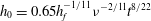 $h_{0}=0.65h_{f}^{-1/11}\unicode[STIX]{x1D708}^{-2/11}t^{8/22}$
for
$h_{0}=0.65h_{f}^{-1/11}\unicode[STIX]{x1D708}^{-2/11}t^{8/22}$
for
 $\unicode[STIX]{x1D708}=1.0$
and
$\unicode[STIX]{x1D708}=1.0$
and
 $0.001$
. (b) Dimensionless radius
$0.001$
. (b) Dimensionless radius
 $R$
versus dimensionless time
$R$
versus dimensionless time
 $t$
for initially cold and hot prewetting films and the same sets of parameters
$t$
for initially cold and hot prewetting films and the same sets of parameters
 $(\unicode[STIX]{x1D708},Pe)$
. Dotted lines: scaling laws
$(\unicode[STIX]{x1D708},Pe)$
. Dotted lines: scaling laws
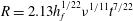 $R=2.13h_{f}^{1/22}\unicode[STIX]{x1D708}^{1/11}t^{7/22}$
for
$R=2.13h_{f}^{1/22}\unicode[STIX]{x1D708}^{1/11}t^{7/22}$
for
 $\unicode[STIX]{x1D708}=1.0$
and
$\unicode[STIX]{x1D708}=1.0$
and
 $0.001$
. (c) Dimensionless effective viscosity versus dimensionless time
$0.001$
. (c) Dimensionless effective viscosity versus dimensionless time
 $t$
for initially cold and hot prewetting films and the same set of parameters
$t$
for initially cold and hot prewetting films and the same set of parameters
 $(\unicode[STIX]{x1D708},Pe)$
. The initially cold film is set with
$(\unicode[STIX]{x1D708},Pe)$
. The initially cold film is set with
 $\unicode[STIX]{x1D6E9}_{b}=0$
and
$\unicode[STIX]{x1D6E9}_{b}=0$
and
 $\unicode[STIX]{x1D6FF}=h/2$
. The initially hot film is set with
$\unicode[STIX]{x1D6FF}=h/2$
. The initially hot film is set with
 $\unicode[STIX]{x1D6E9}_{b}=1$
and
$\unicode[STIX]{x1D6E9}_{b}=1$
and
 $\unicode[STIX]{x1D6FF}=10^{-4}$
.
$\unicode[STIX]{x1D6FF}=10^{-4}$
.


