


INTRODUCTION
The Laser Megajoule (LMJ) Facility, under construction near Bordeaux in France and the National Ignition Facility (NIF) at Livermore in the United States are being built to study fusion by inertial confinement (Besnard, Reference Besnard2007; Sangster et al., Reference Sangster, McCrory, Goncharov, Hardin, Loucks, McKenty, Meyerhofer, Skupsky, Yaakobi, MacGowan, Atherton, Hammel, Lindl, Moses, Porter, Cuneo, Matzen, Barnes, Fernandez, Wilson, Kilkenny, Bernat, Nikroo, Logan, Yu, Petrasso, Sethian and Obenschain2007). Both facilities will be equipped with about 200 laser beams that will focus on a 2 mm diameter cryogenic target filled with a deuterium-tritium (DT) mixture. The target will be held by a cold grip situated at the end of a 6 m carbon boom. When inertial fusion is proved at these facilities, it will be necessary to prove that it is possible to shoot on several targets each second to produce the energy of a power plant. For this reason, target technology and delivery techniques are a key issue for the success of inertial fusion energy. Many groups in the world are working on these topics (Baclet et al., Reference Baclet, Bednarczyk, Botrel, Bourcier, Breton, Collier, Fleury, Legaie, Schunk, Perin, Reneaume and Theoblad2004; Koresheva et al., Reference Koresheva, Osipov and Aleksandrova2005; Nobile et al., Reference Nobile, Nikroo, Cook, Cooley, Alexander, Hackenberg, Necker, Dickerson, Kilkenny, Bernat, Chen, Xu, Stephens, Huang, Haan, Forsman, Atherton, Letts, Bono and Wilson2006; Goodin et al., Reference Goodin, Alexander, Brown, Callahan, Ebey, Frey, Gallix, Geller, Gibson, Hoffer, Maxwell, McQuillan, Nikroo, Nobile, Olson, Petzoldt, Raffray, Rickman, Rochau, Schroen, Sethian, Shelika, Streit, Tillack, Vermillion and Valmianski2005).
For the LMJ, the targets are hollow spheres filled by permeation at ambient temperature then cooled down under the triple point of the DT mixture (19.79 K). Before the shot, the temperature must be controlled within stability better than ±2 mK and the positioning must be performed with a precision better than 5 µm.
The cryogenic targets (Fig. 1) are filled and cooled down in the CEA of Valduc then transported, with their thermal shroud, to Bordeaux (CEA CESTA) in a specific cryostat, which contains six targets at a temperature between 22 and 30 K. Then, they are taken off the cryostat to be transferred with a transfer robot (still with their thermal shroud) to the cryogenic target positioner. After conformation of the solid DT layer, which can last several hours, the cryogenic target positioner drives the target to the center of the 10 m in diameter vacuum vessel. Here, the shroud is slowly disengaged of the target base by the shroud remover situated at the opposite port of the cryogenic target positioner. During this phase, the temperature of the target must not vary more than ±2 mK. Then, the accurate alignment of the target is performed and just before the laser shot, the shroud must be removed very quickly (0.5 m in 0.1 s). This concept, proposed by our laboratory 10 years ago, made some technological problems emerged. For this reason, a large program for the development of prototypes was initiated to validate some technical solutions, which is now called the “French concept.” Thus, the following were developed: a cryo-compressor able to fill the targets, a cryo-target positioner, a cryogenic transfer robot, and recently the thermal shroud remover prototype.

Fig. 1. (Color online) A view of the cryogenic target with its thermal shroud.
A REVIEW OF THE PROTOTYPES DEVELOPED
The Cryo-Compressor
The filling of the LMJ targets is carried out by permeation through the wall of the micro-balloon. To have the required quantity of matter, the pressure in the micro-balloon must lie between 1000 and 1500 bars at the ambient temperature. To prevent that the targets do not break down under the effect of the pressure, the pressure difference between the internal and external walls must be controlled. Our laboratory tested an original idea to solve this problem. DT mixture is liquefied in a small volume in connection with the filling cell maintained at 300 K (Fig. 2). Then this small volume is heated from 20 K to 300 K by controlling the temperature on the wall. This system is able to limit the rise in pressure (ΔP on the micro-balloon wall) and it is possible today to ensure a slope from 0 to 2 bars per minute. This cryo-compressor was delivered to the research center of Valduc during the summer 2003 to be installed in a tritium cell. The construction of two compressors working out of tandem was committed at the end of 2005. This system will have to ensure the production of the targets for one period of at least 30 years.

Fig. 2. (Color online) Principle of the thermal cryo-compressor.
The Target Positioner and Transfer Robot
Once the targets are filled, they are cooled to around 25 K and, in any case, they cannot be heated without being destroyed. It was necessary to develop cryogenic grips, which will be able to handle the targets at a temperature close to 20 K. These grips must provide two important functions: the transfer of heat (power dissipated by T2 and radiation heat load) and the transfer of information. The coating of surfaces was studied in order to obtain thermal resistances of contact between the target and the grip as low as possible. This point is extremely important, because this thermal resistance, being inversely proportional to the temperature, conditions the size of the cold source. Our laboratory undertook a research program to solve the problem of thermal contact resistance and today we are able to carry out thermal contacts of low resistance (1 K/W) at 17 K. During transfers, the temperature of the target must be known, it obliges the grip to ensure reliable electrical contacts and thus free from any trace of pollution, which obliges to ensure the transfers under a very good vacuum. Today procedures of manufacture of the targets are setup to guarantee this criterion of thermal resistance. The cryogenic grip is a key point of the cold chain. Its development required several years and will still require improvements. It is one of the most important technological bolts that it was necessary to solve in priority. Figures 3 and 4 show the cryostats developed to validate the concept of cryogenic transfer, thermal regulation, and target positioning (Paquignon et al., Reference Paquignon, Brisset, Lamaison, Manzagol, Chatain, Bonnay, Bouleau and Périn2005). With these prototypes, we have demonstrated that it is possible to transfer a target from the transfer robot to the target positioner automatically (two cameras drives the hexapod) at a temperature of 23 ± 2 K. After the connection of the target on the target positioner, the thermal regulation of the target base at a temperature of 18 K can be achieved with stability better than 1 mK during several hours. The specific hexapod developed for the target alignment can move the target in a cube of 100 mm with a precision of 50 µm. A rotation of ±3° is possible around the three axes.

Fig. 3. (Color online) A view of the target positioner prototype and the cryogenic transfer robot.

Fig. 4. (Color online) A zoom of the grip of the target positioner and the grip of the transfer robot.
The Thermal Shroud Remover
The thermal shroud of the LMJ target has two functions: it protects the target from the vessel radiations and avoids condensation on the laser entrance hole (LEH). It must be removed 100 ms before the laser shot. As shown in Figure 5, the shroud extraction will be performed with a specific device situated at the opposite port of the cryogenic target positioner. It is composed of a 6 m carbon boom at the end of which is fixed a hexapod. The extraction device is fixed on the mobile part of the hexapod (Fig. 6); it is equipped with a cryogenic grip. The extraction is performed in two steps: the first step consists in disengaging slowly the shroud from the target base; the second step consists in the fast extraction just before the shot. During the first phase, the movement must be very slow because the temperature of the target must not vary more than 2 mK. During the second phase, the displacement has to be of 0.5 m within 100 ms. This is achieved with two springs.

Fig. 5. (Color online) A view of the vacuum chamber and the two cryostats.

Fig. 6. (Color online) A view of the target shroud remover on the moving part of its hexapod.
Keeping the temperature stability during the gripping and removing phases of the shroud are difficult points. It was decided to build a prototype to test technical solutions. This prototype, shown in Figure 7, operates since the spring of 2007. Many experiments have already been performed. The temperature stability at ±2 mK during the gripping and removing phases of the shroud was obtained by using the following method: (1) Control of the target base temperature at 18 K ± 1 mK by adjusting the helium flow rate in the heat exchanger of the target grip (a flow rate of 2300 NL/h is necessary) and by acting on the heater of the target base. At this time the shroud temperature is about 32 K (about 1.2 W (radiation) falls on the shroud and the thermal contact resistance between the shroud and the target base is about 12 K/W at 20 K); (2) The temperature of the shroud remover grip is stabilized at the same temperature as that of the shroud then the shroud remover is slowly approached; (3) The shroud grip catches the shroud very slowly. This operation lasts about 10 mn. The clamping force is 800 N; (4) The shroud grip temperature is slowly decreased (we should obtain 18 K but for the moment the lowest temperature we could have is 21 K. This will soon be improved); (5) The shroud is removed at a speed of 20 µm/s. Figure 8 shows a typical temperature curve of the target base during the shroud removing.

Fig. 7. (Color online) A view of the thermal shroud remover prototype.

Fig. 8. (Color online) Temperature stability of the target base during the shroud removing.
HIPER FACILITY
The HIPER facility consists in a 10 m vacuum chamber at the center of which a 2 mm in diameter cryogenic target is irradiated by 40 laser beams (Dunne, Reference Dunne2006). The energy of the laser beams is 200 kJ in 5 ns. The energy of the PW beam line is 70 kJ in 10 ps. The awaited gain is 100.
In a first step, to validate the fast ignition concept, the laser shot will be performed on one direct drive target equipped with a cone as shown in Figure 9. The target is a hollow sphere filled with DT. It is a direct drive target. The dimensions are as follows:
External radius of DT: 1.044 mm
Internal radius of DT: 0.833 mm
Vapor density: 0.1 mg/cm3 (that means a temperature of 16.3 K)
Solid DT volume: 2.35 mm3
Solid DT mass: 593 µg
β heating power: 116 µW

Fig. 9. (Color online) A schematic view of the direct drive target with its cone.
Conceptual Design Proposed for the HIPER Target Single Shot
As shown in Figure 10, we propose to use a direct drive target filled with a capillary. The capillary could be connected to the cone and the cone must be drilled to drive the DT mixture inside the micro-balloon. If we are able to make this assembling, that will simplify enormously the HIPER cryogenic infrastructure. No high pressure filling station and no cryogenic transfer robots will be necessary.

Fig. 10. (Color online) A schematic view of the assembled target. (a) Case of filling by an external tube. (b) Case of filling by using a reservoir.
The two proposed concepts proposed in Figure 10 have each advantages and disadvantages which are summarized in the Table 1.
Table 1. Table giving the advantages and disadvantages of the two target concept

The problem of the tightness at 300 K could kill the concept of Figure 10B but a valve (or a membrane which could be pierced at the last moment) could be used between the reservoir and the micro-balloon.
This kind of target can be assembled by hands at ambient temperature on a target positioner which could be similar to the one developed for the LMJ. After the assembling, the cryostat will be pumped to a pressure of 10−6 mbar (to avoid the problem of condensation on the target) and then the target will be cooled by the helium cryo-line (or a cryo-cooler).
Conceptual Design Proposed for the Thermal Shroud of the HIPER Target
The thermal shroud could be similar as the one developed for the OMEGA facility of Rochester but this shroud is very complex and could be simpler for HIPER. As for OMEGA, it must be tight because it contains helium gas which cools down the target. It must be equipped with windows for the laser alignment and for the characterization of the DT layer, and will probably have to be equipped with a layering sphere.
Figure 11 shows a concept of thermal shroud which could be a solution for the HIPER target. It consists in a thermal shroud (made of golden platted aluminum) connected to the target base at ambient temperature. A polymer membrane between the target base and the shroud will provide the tightness to helium. As for the LMJ, the removing of the shroud will be done in two steps: (1) In the first step (Figs 11A and 11B) the shroud is slowly removed with the cryogenic shroud remover until the disconnection of the target base. At this time, the target can be aligned at the focus point of the laser beams with the required accuracy. During the alignment phase, the membrane continues to provide the tightness to helium. (2) In the second step, the shroud is quickly removed by the shroud remover and the membrane is torn (Fig. 11C)
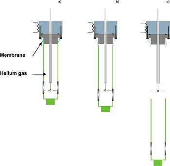
Fig. 11. (Color online) Conceptual design of the proposed HIPER thermal shroud. (a-b): slow disconnection of the thermal shroud before the target alignment. (c): Quick removing before the shot (the membrane is torn).
The development of this concept needs to solve some problems, in particular, the problem of the membrane. Some preliminary experiments must show the tightness and the suppleness of such a membrane at low temperature. Some calculations of heat transfer between the shroud and the micro-balloon will soon begin. These calculations must give, versus the geometry, the optimal helium pressure in the shroud to limit the convections effects on the DT layer geometry.
CONCLUSION
Basing on the experience acquired by our laboratory in the development of cryogenic systems for LMJ, we propose a concept for the HIPER cryogenic system. For the single shot phase, we propose to use targets filled by a thin capillary and cooled down by the target positioner equipped with a hexapod and a helium cryoline similar to the one developed for the LMJ. The thermal shroud of the target will be connected to the target base. A specific membrane must be developed to provide tightness of helium contained in the shroud. The shroud could be removed before the laser shot by a cryogenic shroud remover also similar to the one developed for the LMJ.
ACKNOWLEDGEMENTS
The authors would like to thank S. Bressieux, M. Charvin, P. Dalban-Moreynas, J. Inigo, T. Jourdan, J. M. Mathonnet, P. Nivelon, and M. Saggioro for their contribution in the development of all the prototypes described in this paper. The development of the prototypes is supported by CEA/DAM Program LMJ.


