Published online by Cambridge University Press: 02 June 2005
A beam combination laser with stimulated Brillouin scattering-phase conjugate mirrors (SBS-PCMs), which is expected to produce a high output energy and power with a repetition rate over 10 Hz, is a candidate for a practically useful laser fusion driver in the future. In order to develop the beam combination laser with SBS-PCMs, it is necessary to control the phase of each SBS wave whose phases are known as inherently random. We have proposed a new phase control technique and demonstrated experimentally that the relative phase difference between two SBS waves can be controlled to a certain value and locked to it with an accuracy less than λ/4. Additionally we have proposed and demonstrated a new technique to preserve the pulse shape of the SBS wave. Based on these experimental results, we have proposed two schemes of the new schemes for the high repetition and high energy/power beam combination laser system (laser fusion driver) using the SBS-PCMs of amplitude division and wave-front division techniques, which can operate with repetition rate over 10 Hz, in this paper.
For achieving a high power laser with a repetition rate over 10 Hz, which is required for a laser fusion driver, several methods have been widely investigated by many researchers such as a beam combination technique, a diode pumped laser system with gas cooling, an electron beam pumped gas laser, and a large sized ceramic Nd: YAG (Hogan et al., 1995; Kong et al., 1997; Rockwell & Giuliano, 1986; Loree et al., 1987; Lu et al., 2002). Especially, the beam combination method seems to be one of the most practical techniques for this application (Kong et al., 1997; Rockwell & Giuliano, 1986; Loree et al., 1987). The laser system using a beam combination technique, in which a laser beam is divided into several beams and recombined after separate amplification and does not need a large gain medium. Hence, it can operate at a repetition rate exceeding 10 Hz regardless of the output energy and is easily adaptable to the modern laser technology. Kong et al. (1997) proposed a promising beam combination laser system using the stimulated Brillouin scattering-phase conjugate mirrors (SBS-PCMs), whose output energy can be unlimitedly scaled up by increasing the number of separate amplifiers. In addition, the SBS-PCMs produce a phase conjugated wave to compensate many kinds of optical distortions in the system, induced during the amplification (Rockwell, 1988). In the beam combination laser using SBS-PCMs; however, it is necessary to control the phase of each beam reflected by the SBS-PCM to get the good beam recombination. It has been known that the phase of the beam reflected by SBS-PCM is inherently random (Loree et al., 1987; Lu et al., 2002; Rockwell, 1988; Boyd et al., 1990) because SBS starts from a noise in the SBS medium. There have been several works to control or lock the phases of SBS wave, and some of them are very successful (Rockwell & Giuliano, 1986; Loree et al., 1987). By overlapping the laser beams at one focal point, the phases are almost locked (Rockwell & Giuliano, 1986). However, since all the beams must be focused at one point, the energy scaling is limited, and the beams are not symmetrically focused at the focal spot. The back seeding of the Stokes beam overcomes the above drawbacks (Loree et al., 1987), but the phase conjugation is incomplete if the injected Stokes beam is not completely correlated. In this paper, we have proposed and demonstrated a new phase control technique, wherein each beam is focused at separate focal points without using any backward Stokes seed beams, and hence, the energy scaling is not limited and the phase conjugation is not disturbed at all. For getting a given output energy, we may simply install the proper number of amplifier lines in parallel for beam combination, because the whole system is alignment insensitive in this new laser systems.
The acoustic wave, Brilluin grating, is simply represented as

propagating in the positive z direction, where ρ(z,t), q, and Ω are the amplitude, the wave vector, and the frequency of the acoustic wave, respectively. The initial phase is given by φa = qz0 − Ωt0, where z0 and t0 are known to vary randomly because the acoustic wave begins from a random acoustic noise (Boyd et al., 1990). However, we have found it is possible to decide z0 and t0 by putting a mirror in the back of the SBS-PCM to make a standing wave at the focus (Kong et al., 2004). One of the standing wave is the candidate of the ignition position z0, and t0 = tc is determined by the pumping energy Ep from the equation,

where Ec and P(t) are the SBB threshold energy and the pumping pulse form, respectively, and t0 = tc as described in Kong et al. (2004).
Figures 1, 2, and 3 shows the theoretical values of the ignition time (tc), phase uncertainty (Δφ), and the relative phase difference uncertainty (ΔΦ) depending on the pumping energy, respectively. It should be noted that Δφ is inversely proportional to the pumping energy Ep.
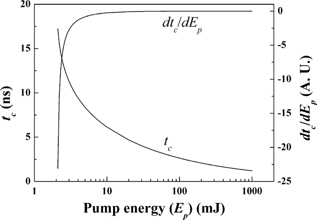
tc & dtc /dEp as a function of the pump energy.
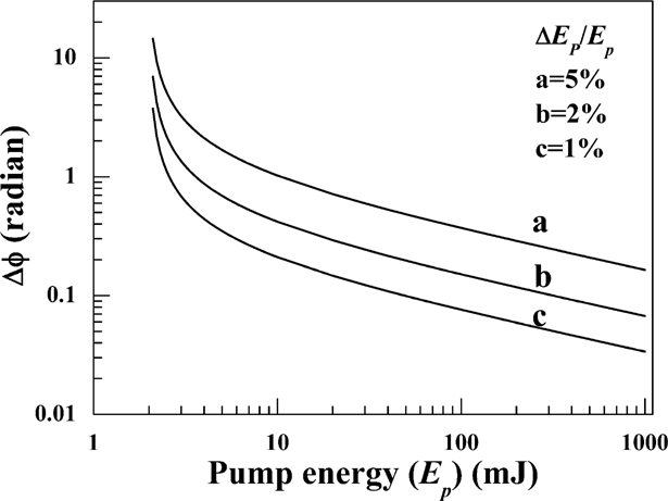
Phase change of the SBS wave as a function of the pump energy (ΔEp /Ep = 1, 2 and 5%).
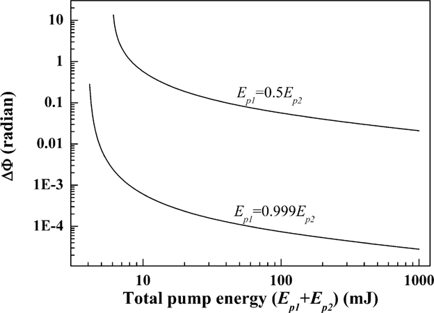
Change of the relative phase difference as a function of pump energy for the cases of Ep1 = 0.5Ep2 and Ep1 = 0.999Ep2.
We have measured the relative phase difference Φ = φ1 − φ2 between two Stokes beams for the case of the amplitude dividing. The experimental setup is shown schematically in Figure 4. A Q-switched 1064 nm Nd:YAG oscillator with a bandwidth of ∼ 120 MHz and ∼ 2% energy stability was used for the pump. The pulse width was 7 to 8 ns and the repetition rate was 10 Hz. The output from an oscillator is divided into two sub-beams by a beam splitter (BS). Both beams then pass through the separate wedges (W1 & W2) and are backward focused into each SBS-PCM. The wedge reflects a part of the backward Stokes beam, which is overlapped with that of the other Stokes beam, onto a CCD camera to get an interference pattern of them. For stabilizing the phase by the self-generated density modulation, the pump pulse is backward focused by a concave mirror with R = 50 cm and reflectivity > 99%. The density modulation is induced by the electrostriction in the SBS material, especially at the focal area by the standing wave interference pattern at the focal region. We used Fluorinert FC-75 as a SBS medium. The length of a SBS cell of 50 cm is used in this experiment (Yoshida et al., 1997).
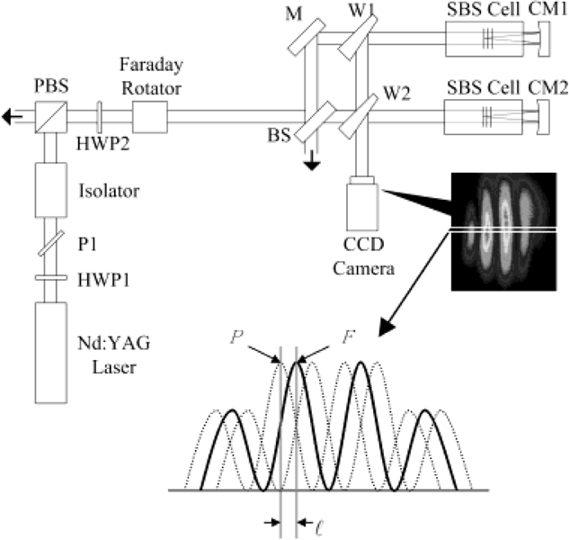
Experimental setup for measuring the relative phase difference; HWP1 & HWP2; half wave plate; BS; beam splitter; M; mirror; W1 & W2; wedges; P1; polarizer; PBS; polarization beam splitter; CM1 & CM2; concave mirrors.
The diagnostics for the phase control of the Stokes beams is straightforward. The interference pattern acquired by the CCD camera yields the relative phase difference Φ = φ1 − φ2 between the Stokes beams incident on the CCD, where φ1 and φ2 denote the phases of two Stokes beams, respectively. Therefore, we can quantitatively analyze the degree of the phase stabilization by measuring the movement of the peaks. From the interference pattern of every shot, the intensity profile of its horizontal line is selected and stacked as shown in Figure 4. A peak position P is then determined from the selected line. Since the relative phase difference Φ between two beams fluctuates, the peak position P also moves to the left or right with respect to a fixed point F. The relative phase difference Φ can be expressed as 2π[ell ]/T, where [ell ] is the distance between F and P and T is a spatial period of the interference pattern.
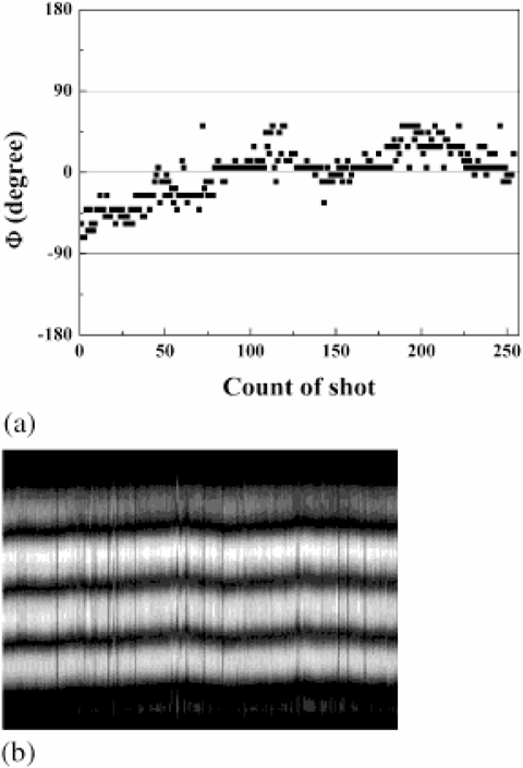
We have measured Φ for two specific cases of Ep1 ≅ Ep2 and Ep1 ≅ 0.5Ep2. Figure 5 shows the experimental results for the case of Ep1 = 9.4 mJ and Ep2 = 4.66 mJ. Each point in Figure 5a represents one of 256 laser pulses. Figure 5b shows the intensity profile of 256 horizontal lines selected from each interference pattern. It shows that there is something missing for phase locking.
Figure 6 shows the experimental results for the case of Ep1 = 10.56 mJ and Ep2 = 10.55 mJ. The relative phase difference between two SBS waves is smaller than λ/4 for every shot. Compared to the previous results, the fluctuation of relative phase difference is considerably reduced. The profile also represents that the relative phase difference is stabilized quite a lot. The experimental results qualitatively agree with the theoretical results in Figure 3. Consequently, we have shown that it is possible to control and lock the relative phase difference by a self-density modulation, provided that the energies of the two beams are made similar.
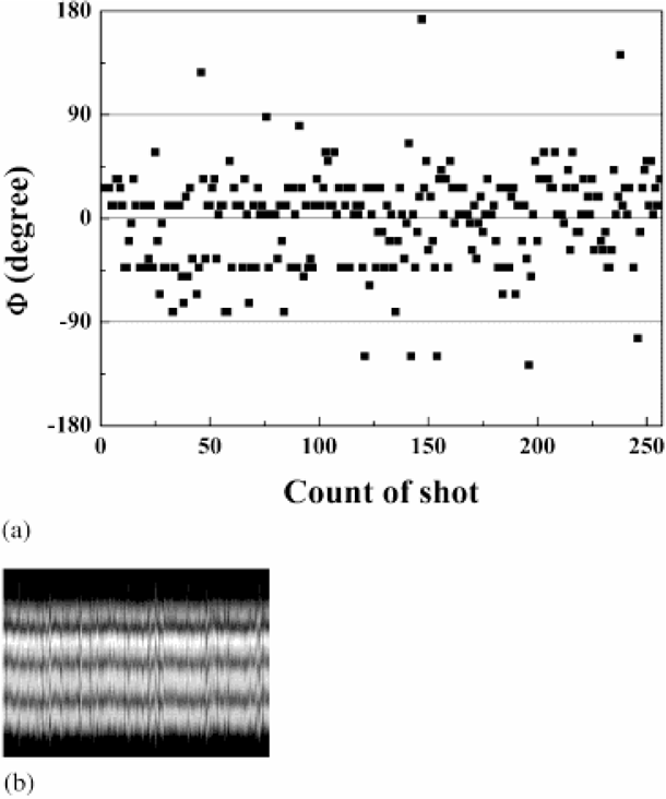
(a) Relative phase difference for 256 laser pulses and (b) Intensity profile of horizontal lines selected from 256 interference patterns for the case of Ep1 = 9.4 mJ and Ep2 = 4.66 mJ.
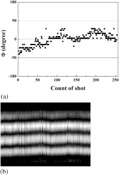
(a) Relative phase difference for 254 laser pulses and (b) Intensity profile of horizontal lines selected from 254 interference patterns for the case of Ep1 = 10.56 mJ and Ep2 = 10.55 mJ.
The wave form is deformed by the SBS reflection, due to the consumption of the front part of the wave energy for the formation of the acoustic grating formation and the extension of the interaction zone during the pulse propagation. We have found it is possible to keep the wave form by using the pre-pulse technique (Kong et al., 2005). Figure 7a is the input pulse, Figure 7b is the SBS wave without pre-pulse, Figure 7c is the SBS wave with pre-pulse, Figure 7d is the comparison of the input pulse, and the SBS wave. From these experimental results, it is clear that the pre-pulse technique is quite useful to preserve the pulse shape.
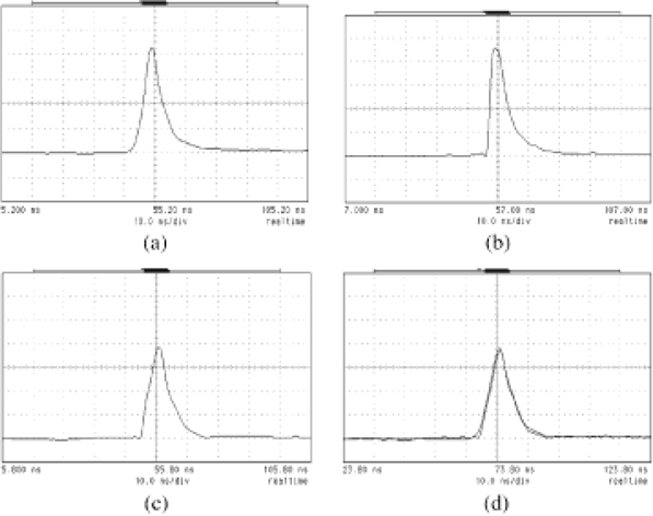
The pulse shapes, (a); input wave, (b); SBS wave without pre-pulse, (c): SBS wave with pre-pulse, and (d); comparison of the input pulse and SBS wave with the pre-pulse.
We have proposed two laser fusion drivers of amplitude dividing and wave-front dividing schemes as shown in Figures 8a and 8b. With the phase controlling technique and the pre-pulse technique described upper, we can produce huge output energy as we want by scaling-up. The wave-front dividing scheme was proposed already by one of the authors in 1997 (Kong et al., 1997). Also these proposed laser systems are alignment insensitive so that it is very easy to install or maintain the system because we may just put the components in their position with the mechanical accuracy not optical accuracy. Also this system requires low quality of the optical components but the polarizing components, because the optical distortions caused by the low quality optical components and during the amplifications in the gain media can be compensated by this system automatically.

Schematic diagrams of the proposed laser fusion driver with SBS-PCM beam combination; (a) amplitude dividing scheme and (b) wave-front dividing scheme: PC; phase controller, PP1 and PP2; prepulsers, AMP1 and AMP2; amplifiers, FR1 and FR2; faraday rotators, IR1 and IR2; image relays, WD1 and WD2; wave-front dividers, BE1 and BE2; beam expanders, PBS1; polarizing beam expanders, QW1 and QW2; quarter wave plates, 45R; 45 degree rotator.
We have proposed a new phase control technique by a self-generated density modulation in order to control the phase of the SBS waves, which is required for the beam combination laser with SBS-PCMs. Theoretical analysis shows that the phase fluctuation is inversely proportional to the pump energy and is proportional to the pump energy fluctuation. By means of the amplitude dividing, we have achieved that the relative phase difference between two SBS waves can be made smaller than λ/4. We expect that this phase control technique is very useful to develop a practically useful laser fusion driver using the beam combination with SBS-PCMs. Even if a large number of amplifiers should be installed in parallel for huge energy/power output, it will be very easy to install or maintain them because of their special characteristics such as the compensation of the optical distortions by the phase conjugated mirrors and the alignment insensitiveness by the cross type amplifier system with the symmetrical SBS-PCMs.
This work was supported by the KISTEP, the RRC at Dankook University, and the IAEA, Austria, contract no. 11636/R2.
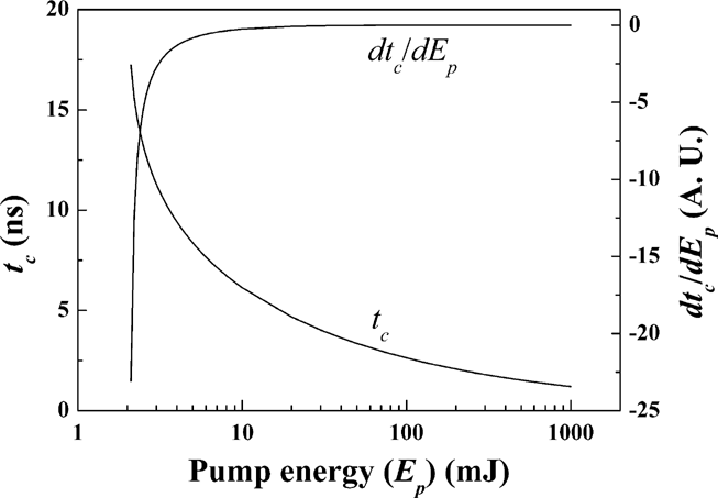
tc & dtc /dEp as a function of the pump energy.
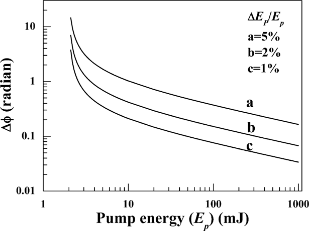
Phase change of the SBS wave as a function of the pump energy (ΔEp /Ep = 1, 2 and 5%).
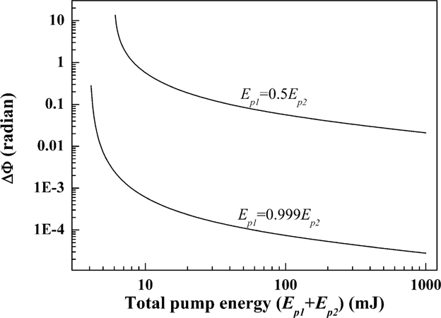
Change of the relative phase difference as a function of pump energy for the cases of Ep1 = 0.5Ep2 and Ep1 = 0.999Ep2.
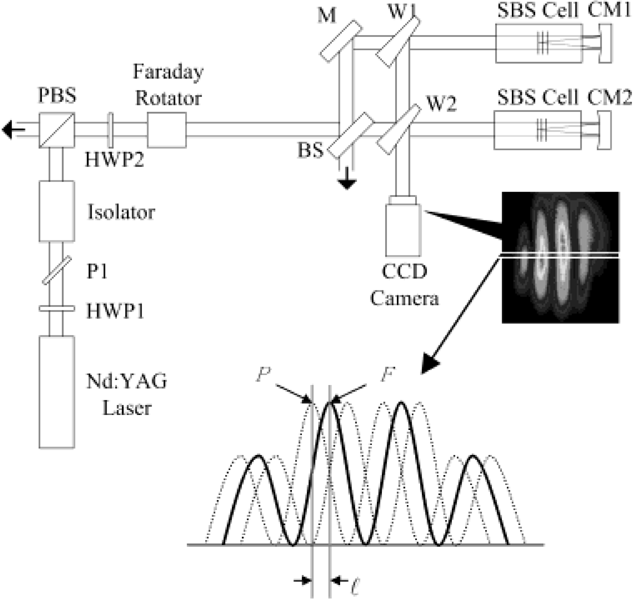
Experimental setup for measuring the relative phase difference; HWP1 & HWP2; half wave plate; BS; beam splitter; M; mirror; W1 & W2; wedges; P1; polarizer; PBS; polarization beam splitter; CM1 & CM2; concave mirrors.
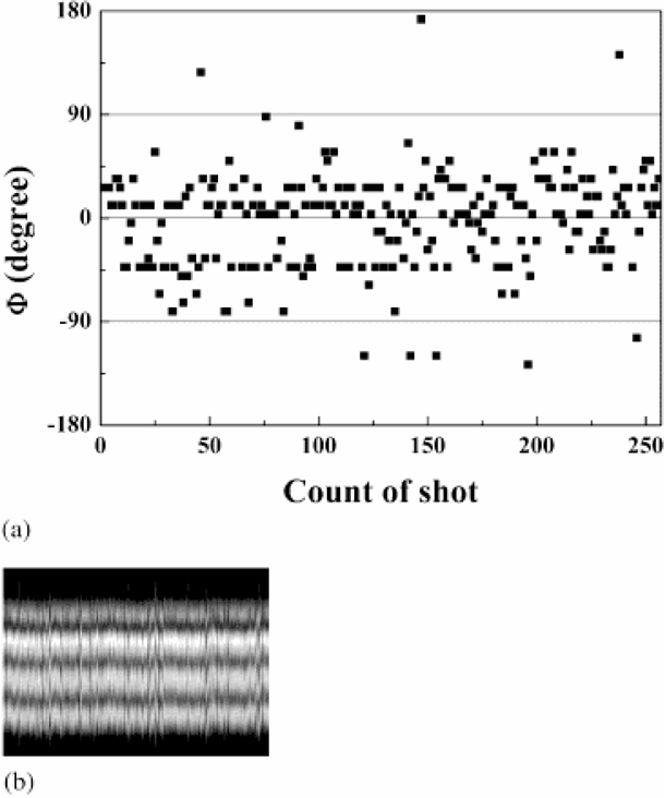
(a) Relative phase difference for 256 laser pulses and (b) Intensity profile of horizontal lines selected from 256 interference patterns for the case of Ep1 = 9.4 mJ and Ep2 = 4.66 mJ.
(a) Relative phase difference for 254 laser pulses and (b) Intensity profile of horizontal lines selected from 254 interference patterns for the case of Ep1 = 10.56 mJ and Ep2 = 10.55 mJ.
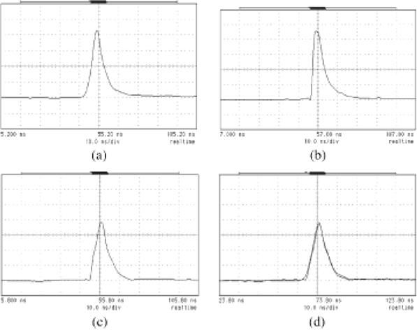
The pulse shapes, (a); input wave, (b); SBS wave without pre-pulse, (c): SBS wave with pre-pulse, and (d); comparison of the input pulse and SBS wave with the pre-pulse.

Schematic diagrams of the proposed laser fusion driver with SBS-PCM beam combination; (a) amplitude dividing scheme and (b) wave-front dividing scheme: PC; phase controller, PP1 and PP2; prepulsers, AMP1 and AMP2; amplifiers, FR1 and FR2; faraday rotators, IR1 and IR2; image relays, WD1 and WD2; wave-front dividers, BE1 and BE2; beam expanders, PBS1; polarizing beam expanders, QW1 and QW2; quarter wave plates, 45R; 45 degree rotator.