


Introduction
For the last 45 years, designers have proposed various shape grammars to accomplish engineering design tasks. After the introduction by Stiny and Gips (Reference Stiny and Gips1972), shape grammars have been created for the design of Palladian architecture (Stiny & Mitchell, Reference Stiny and Mitchell1978), Harley–Davidson motorcycle (Pugliese & Cagan, Reference Pugliese and Cagan2002), and coffee makers (Agarwal & Cagan, Reference Agarwal and Cagan1996) where some exist on paper and others are implemented using a variety of representations (McKay et al., Reference McKay, Chase, Shea and Hing Chau2012). The primary focus of these works has been to model design style and languages and to explore the solution space through the generation of alternative designs. As such, shape grammars have been instrumental in the conceptual design stage. However, since the design requirements for many of these products are difficult to quantify, human designers are often involved in selecting the best design from the generated set (Antonsson & Cagan, Reference Antonsson and Cagan2001). This can be problematic as the human-oriented selection process becomes ineffective when the search space grows (Bar-Yam, Reference Bar-Yam2003). Further, when presented with increasingly complex design challenges, shortcomings such as design fixation (Purcell & Gero, Reference Purcell and Gero1996), confirmation bias (Hallihan et al., Reference Hallihan, Cheong and Shu2012), and difficulty in modeling (Gibson et al., Reference Gibson, Rosen and Stucker2014) may lead to suboptimal designs.
These issues have driven the research area of computational design synthesis (CDS), where computational methods are developed to provide designers with means to automatically generate designs, evaluate them, and search vast solution spaces to find novel solutions and model complex interactions (Chakrabarti et al., Reference Chakrabarti, Shea, Stone, Cagan, Campbell, Hernandez and Wood2011). Integrated into such CDS, shape grammars entail multiple benefits:
• In combination with stochastic optimization, shape grammars are able to produce optimized designs plus a variety of designs that are nearby and yet may have vastly different characteristics and forms.
• Designers can directly incorporate their personal style and/or aesthetics.
• Designers can embed manufacturing constraints within the rule set.
While parametric modeling (Woodbury, Reference Woodbury2010) also allows for direct integration of personal style and manufacturing constraints, the variety of designs is limited as the designer predefines all parametric variations in the model. Hence, it is difficult to generate unexpected or novel designs (Chen & Shea, Reference Chen and Shea2015).
However, to achieve these benefits for engineering problems, a fully integrated system is still needed including quantitative evaluation through simulation. A step toward this was developed in the work of Shea et al. (Reference Shea, Aish and Gourtovaia2005) but was limited to import and export between a structural shape and topology optimization method for three-dimensional (3D) truss structures, based on a structural shape grammar, and parametric CAD. This is challenging to do more generically considering the wide potential variety of designs generated by a spatial grammar and the need to automate the simulation including the definition of boundary conditions and material. Currently, in most cases, these have to be defined manually for each generated design to create a finite-element analysis (FEA) model, which is time consuming and ineffective considering that a spatial grammar can generate thousands of design variants. Thus, this paper focuses on providing a generalized and automated link between the designs generated by a spatial grammar, structural FEA, and computational optimization. This will provide designers, for example, mechanical and product designers, with new means for generative design using spatial grammars that integrate automated feedback of design variants from FEA and optimization to generate optimized solutions.
Figure 1 depicts the framework for CDS that consists of generation, evaluation, and optimization. The generation entails the design and application of grammar rules within a graphical and interactive spatial grammar interpreter spapper (Hoisl & Shea, Reference Hoisl and Shea2011). After a design is generated using the spatial grammar, it is exported and automatically evaluated by FEA, without designer interaction. An objective function value is calculated considering engineering performances, for example, stress and/or displacement, and/or geometric constraints. The objective function values are used in an integrated simulated annealing (SA) algorithm to drive the generative design process. To highlight the uniqueness of this approach compared with continuous topology optimization, constraints from an additive manufacturing (AM) process are modeled in the spatial grammar (Fig. 1, dashed arrow) so that optimized designs can be directly fabricated. Through the provision of an integrated approach, the intention is to provide designers with a simulation and optimization-driven generative system that designers can use and customize directly without the need for programming.
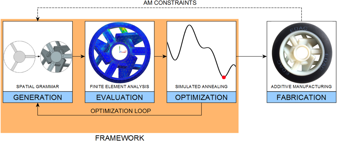
Fig. 1. Framework and fabrication with the example of inline skate wheel spoke design.
The paper begins with a brief background section on the shape grammar formalism and the combination of spatial grammars with optimization and evaluation as well as other related work. The framework is then presented in more detail following the process shown in Figure 1. The section “Engineering design case study: inline skate wheel spokes” presents an engineering case study of inline skate wheel spoke design to demonstrate the benefits of the framework. The paper finishes with a discussion and a conclusion.
Background
Shape grammars
Shape grammars as an approach to shape computation were first introduced in 1972 (Stiny & Gips). The formalism (Stiny, Reference Stiny1980) states that a grammar consists of a set of shapes, rules, and labels, as well as an initial shape. First, a vocabulary of shapes is defined. From this vocabulary, both the left-hand side (LHS) and the right-hand side (RHS) of rules are built. Rules are applied by searching for geometries within the current working shape (CWS) that match the shapes in the LHS of the rule under defined geometric transformations. On detecting matches, one match is selected and the shapes matched are replaced by the RHS under the same geometric transformation.
This work builds on spapper, a visual and interactive spatial grammar interpreter (Hoisl & Shea, Reference Hoisl and Shea2011), which facilitates rule design, implementation, and application for 3D solids in a familiar CAD-based interface for designers. There is no emergence in spapper as it is implemented as a set grammar using CAD primitives, which is why the term spatial grammar is used in this paper. The term spatial grammar was proposed by Krishnamurti and Stouffs (Reference Krishnamurti and Stouffs1993) and provides a generalized view on grammatical approaches to generate form whether they are implemented as strings, sets, graphs, or shapes. Within spapper, users are able to define parametric rules, perform automated matching of the LHS including labels, and translation and rotation transformations as well as automated application of rules (Hoisl & Shea, Reference Hoisl and Shea2013).
Considering the case study of inline skate wheels, the first application of spatial grammars to generate vehicle wheels was to demonstrate spapper, already described. The second piece of research focused on the potential of spatial grammars for generating customized wheel spoke patterns that integrate the spatial constraints of a 3D printing process, so that they can be automatically printed (Chen & Shea, Reference Chen and Shea2015).
Combination of spatial grammars with optimization and simulation
Shape grammars have been combined with different stochastic search algorithms, among which are genetic algorithms. Chouchoulas (Reference Chouchoulas2003) generated room layouts for high-rise buildings with a number of functional requirements as evaluation criteria. Ang et al. (Reference Ang, Chau, McKay and De Pennington2006) generated shapes using a 2D parametric coke bottle grammar that incorporates brand identity, and optimized the designs with a volume-based objective function.
The combination of shape grammars and simulated annealing, called shape annealing, has been proposed by Cagan and Mitchell (Reference Cagan and Mitchell1993). Shea and Cagan (Reference Shea and Cagan1997) developed a generative method using shape annealing to generate and optimize 2D to 3D truss structures from free forms to highly constrained transmission towers (Shea & Smith, Reference Shea and Smith2006). With a small set of reversible parametric rules, they demonstrated that the method can achieve optimally directed solutions to combinatorial problems and can assist designers by enlarging the solution space (Shea & Cagan, Reference Shea and Cagan1999). This work was integrated within a CAD system, but did not enable designers to develop their own structural shape grammars graphically and is limited to truss structures (Shea et al., Reference Shea, Aish and Gourtovaia2005).
There are only a few works in which shape grammars were linked to FEA. In addition to the work described, Barros et al. (Reference Barros, Duarte and Chaparro2015) generated Thonet chair topologies for the back of the chair using a 2D parametric shape grammar. These topologies were then translated into a parametric CAD model already integrated within a FEA model and simulation. This method was designed to solve a specific problem.
These works show that the research focus lies mainly on the combination of shape grammars and stochastic optimization, and much less on the automated integration with FEA. Further, even though FEA is performed in the work of, for example, Barros et al. (Reference Barros, Duarte and Chaparro2015), it limits the design generation since the underlying FEA model is still parametrized. Hence, the present paper contributes by addressing the challenges in linking generated designs to FEA automatically, and thus by generalizing the applicability of such CDS approaches in combination with stochastic optimization that integrates engineering performance evaluated through simulation.
Since the focus in the paper is on automated integration of structural FEA, related work also includes continuous topology optimization (Bendsøe & Sigmund, Reference Bendsøe and Sigmund2013). These methods are powerful in the detail design stage, but are deterministic and driven only by FEA-based performance objectives and so inferior in the variety of solutions generated and in direct integration of personal style and manufacturing constraints. Only one design is produced for a given optimization model, based only on engineering performance, which the user generally cannot directly influence.
Framework
The approach taken in this paper, as shown in Figure 1, provides a framework that integrates a spatial grammar interpreter, automated FEA, and simulated annealing optimization. The fully automated optimization process is as follows: first the spatial grammar generates one design alternative; this is automatically evaluated using FEA and then simulated annealing optimization determines whether the new design is accepted or to revert to the previous design. Each component in the process is now presented along with the challenges in their automated integration. The section concludes with the presentation of a use case of the framework from the designer's perspective.
Generation: spatial grammar
Spatial grammars can range from parametric to non-parametric and from basic to unrestricted (Knight, Reference Knight1999). Both topological rules, that is, rules that add and remove shapes, and sizing rules can be incorporated. Different rule sets can be applied in different stages of the design generation process. To integrate spatial grammars with FEA, we determined the following general guidelines, so that the process can be fully automated:
• Rules should only create manifold solids (Stroud & Nagy, Reference Stroud and Nagy2011). If two or more solids in an assembly are coincident only at a single point or line, the shared interface is non-manifold and thus cannot be interpreted by a number of CAD and FEA systems and are not producible directly with AM. In a local context, that is, just considering one rule, non-manifold designs can be avoided by spatially arranging the RHS solids to always be manifold, as described in Chen et al. (Reference Chen, Stoeckli and Shea2015). Checking if a solid is manifold or not within an assembly of solids is more complex. However, non-manifold solids are deleted when exported, for example, in a step-file (AP214), which is capitalized on by comparing the number of solids that should be exported by the spatial grammar interpreter with the number that is imported into the FEA package. If these numbers differ, the current model is non-manifold and the framework returns the solution and applies a different rule to the CWS.
• Rules should only create connected solids. Non-connected solids lead to errors in the FEA; hence, especially parametric rules have to be designed carefully. An example is that two connected solids must remain connected after the rule is applied. Further examples are given in Chen and Shea (Reference Chen and Shea2015).
• Rules should not create identical designs. The most time-consuming step in the framework is the FEA, which should thus not be performed multiple times for the same design. Attention must be paid to parametric rule sets in particular since the rule sequence does not represent the actual solution that results from the parameter values applied in each rule.
Simulation: FEA
Carrying out a FEA requires a meshed geometry, material assignment, and boundary conditions applied to the mesh. The biggest challenge when creating an automated FEA model is the application of the boundary conditions. For a FE solver to simulate the same load case for each new geometry generated by the spatial grammar, the connection between boundary conditions and the surfaces they are applied to must be preserved. Hence, these surfaces cannot change.
To ensure this, the approach in this work is that a designer partitions the model into smaller components. Figure 2 (top) shows a generic load case with a distributed force on the right and an arbitrary boundary condition on the left. Figure 2 (bottom) shows a possible partitioning, in which parts affected by boundary conditions are separated from the design generated by the spatial grammar. These parts, called invariant components, stay identical throughout the optimization, so that new designs produced by the grammar can be automatically inserted and simulated.
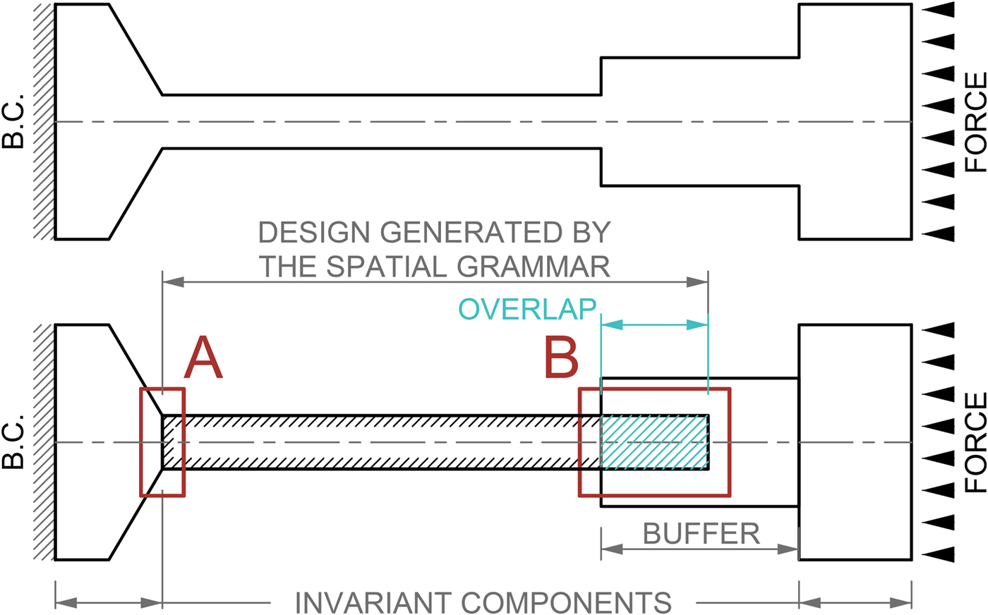
Fig. 2. Generic simulation model (top) and partitioning of the model for automated integration with a spatial grammar (bottom).
However, although partitioned, the components still belong to the same part, and thus have to be united before being analyzed. Figure 2 (bottom) shows two possible situations: In situation A, the new grammar design is guaranteed to be imported at the same spatial location as the last one, and thus shares a 2D interface with the invariant component, in which case they can be united without changing the properties of the invariant component. In case the spatial relations of grammar designs cannot be predicted easily, that is, in situation B, a buffer part has to be introduced to ensure a connection between each new design generated and the invariant component. If the design consists of multiple materials, surface contact conditions must be introduced between components, which also require a buffer.
Setting up the FEA model properties, designers specify the load case, boundary conditions, mesh, and material assignment, but with a partitioned model. Subsequently, as the only addition, they provide information about which components are invariant, buffer, or belong to the design generated by the grammar, that is, will be replaced.
Independent of the number of solids contained within the generated design, the number of buffer parts and invariant components, a Unite feature is inevitable in the FEA model. This Unite feature is the key to the automatic replacement of new grammar designs, because no matter how many parts are united, mesh and boundary conditions reference to only that feature. Hence, the framework is implemented in such a way that it replaces the previous design generated by the grammar with the new one without changing the identity of the Unite feature. Hence, the Unite feature, as well as the boundary conditions remain unchanged, the mesh is regenerated automatically, and the FEA can be performed. The replacement is possible for any number of new solids, that is, the number of old and new solids can differ.
Engineering performance such as maximum stress or displacement are automatically determined from the FEA results and provided to the optimization algorithm.
Optimization: simulated annealing
For optimization algorithms to be generally applicable to spatial grammar systems, non-linear and multimodal search spaces have to be anticipated. Spatial grammars further create discontinuous search spaces as a consequence of the shape transformations that add and remove shapes. Depending on the generative power of the grammar (Knight, Reference Knight1999), search spaces can be vast, where variety is usually a result of parametric rules rather than the size of the rule set. A few rule applications can generate many solutions; hence, a breadth-prioritized search algorithm is favored. Simulated annealing has been used to optimize large search spaces (Dowsland & Thompson, Reference Dowsland, Thompson, Rozenberg, Bäck and Kok2012) and works well in conjunction with spatial grammars (Shea & Cagan, Reference Shea and Cagan1997). Simulated annealing is robust, can be tailored to optimization problems with the requirements already mentioned and is therefore employed in this framework.
Distinct rule sets, for example, topology and parametric sizing rules, pose a challenge for optimization methods that are linked to engineering design grammars (Konigseder & Shea, Reference Konigseder and Shea2016). Hence, the framework provides the option to divide the optimization into multiple stages in which different rule sets are applied. In the case study described in the section “Engineering design case study: inline skate wheel spokes”, for example, there are ten topology rules, three sizing rules, and one post-processing rule (Fig. 3). In the first stage, both topology and sizing rules are applied, so that topologically different, but also feasible designs are found. The second stage continues with the best design from the first stage and directs the sizes of the members toward an optimized solution only through sizing rules. The last stage is a post-processing stage to delete any unnecessary solids.
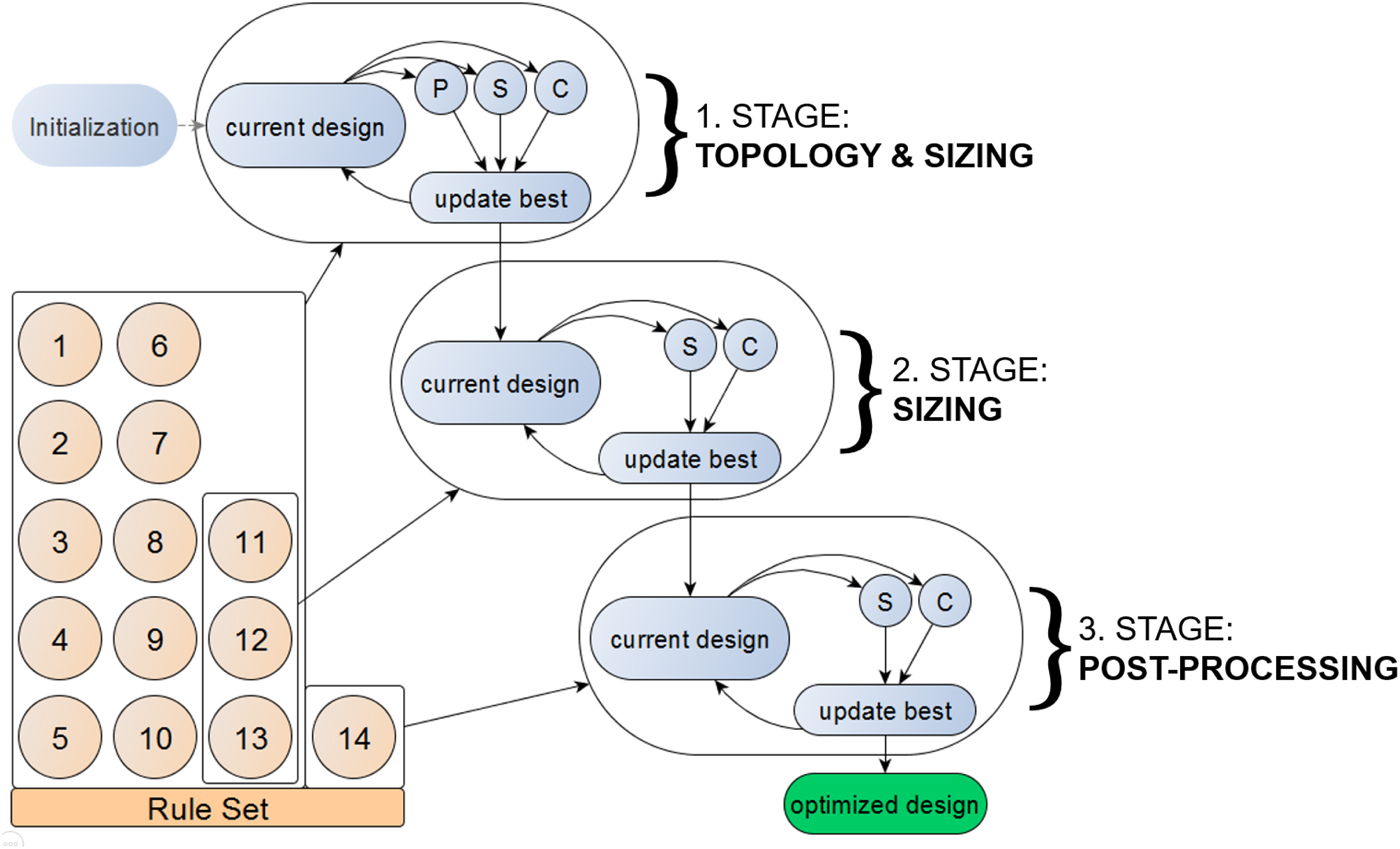
Fig. 3. Simulated annealing in three stages for the wheel grammar.
The definition of the neighborhood that is used for selecting which rule to apply next has an influence on the outcome of the optimization. This was shown in Shea (Reference Shea1997) through the use of the “Hustin” rule sets where a rule type, that is, topology or geometric rule, is selected probabilistically and each geometric rule has a parametric neighborhood defined that specifies the maximum parametric change. A neighbor should be in close proximity to the current solution but far enough, so that all solutions in the search space can be reached (Dowsland & Thompson, Reference Dowsland, Thompson, Rozenberg, Bäck and Kok2012). In this paper, we provide a new neighborhood definition for rule selection that considers the neighborhood of topological rules and sequences of rules rather than only probabilistic selection of single rules and parametrically defined neighborhoods.
Figure 4 shows a part of the search tree of a grammar system with seven rules. Each circle denotes a possible solution, the numbers in the middle stand for the rule sequence. The current design 1 → 3 → 5 is thus created by applying the rules 1, 3, and 5 in that sequence to the initial shape. The neighborhood of the current design is defined as the choice between a parent, a sibling, or a child solution. A child results when a new rule is applied to the current design, for example, 1 → 3 → 5 → 6. For a sibling, the last applied rule is replaced with a new rule (or the same rule with a set of different parameters), for example, 1 → 3 → 4. A parent is achieved by removing the last applied rule and replacing the previous one with a new rule (or the same rule with a set of different parameters), for example, 1 → 7. Exchanging rules in any other part of the sequence than its tail, for example, from 1 → 3 → 5 to 2 → 3 → 5 or to 1 → 4 → 5 will result in topologically disparate solutions because previous rules have much more influence on the design than later ones.

Fig. 4. Definition of the neighborhood for spatial grammar-based simulated annealing.
Use case
Using the described framework from the designer viewpoint shown in the middle, Figure 5 shows the three components of the framework and the necessary inputs by the designer. The designer first provides the initial shape to FreeCAD 0.12, the open source CAD software that runs spapper, together with the spatial grammar rule set that was built in spapper. The initial shape includes either a single primitive or an assembly of primitives contained within the vocabulary of the rule set. The initial solution consists of the same solids as the initial shape, but is prepared in such a way that parts of it can be automatically replaced by subsequent designs generated by the grammar. This preparation is dependent on the FEA model properties, for example, boundary conditions and material distribution. Both initial solution and FEA model properties are inputs to Siemens NX 8.5, a commercially available CAD software. The last input is the optimization model, which defines the objective function, the constraints, and the parameter settings for the simulated annealing algorithm written in Python.
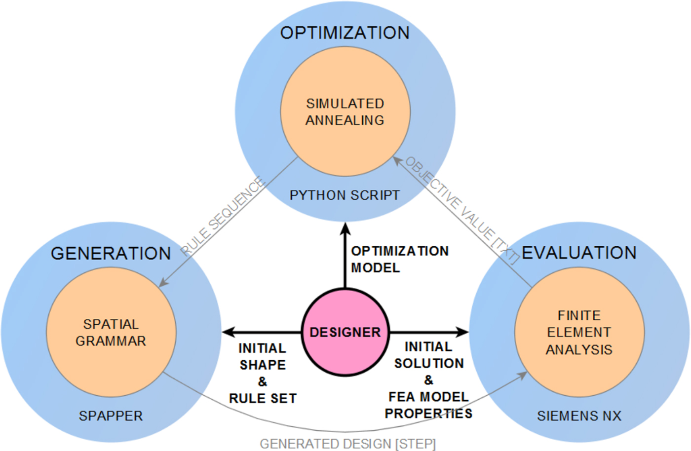
Fig. 5. Framework with designer input.
Hence, the designer is both grammar developer, using the visual interface of spapper, and user of the grammar interpreter, as defined by Chase (Reference Chase2002), and additionally defines the load case and the optimization model.
Engineering design case study: inline skate wheel spokes
The framework is used to design and optimize spokes of inline skate wheels. Inline skate wheels entail a range of characteristics to show the merits of the framework. First, the main engineering performance is structural strength and requires solid, 3D structures. Second, spatial grammars are capable of capturing the individual style of a designer, or customer, and inline wheels require aesthetic appeal and can be mass customized. Third, they consist of different materials, that is, the tire is made of compliant elastomer and the spokes of stiff plastic (Keleny, Reference Keleny1999), which renders them a good case study for the FEA model properties and for state-of-the-art multi-material AM, for example, the Polyjet 3D printing process.
The following sections provide the case study-specific information to demonstrate the methods in the framework.
Inline skate wheel grammar
The rules of the inline skate wheel grammar developed using spapper are illustrated in Figure 6 and described in detail in Table 1. The generative power of this grammar ensues from two properties.
Fig. 6. The inline skate wheel grammar. The LHS is always the same indicated in the center and the orange shape in each rule indicates the LHS of the rule superimposed onto the RHS.
The first property is that the LHS for all rules is the same shape, depicted in the middle of Figure 6 and in the surrounding RHSs as translucent objects in orange. Some rules require the LHS to be of a certain minimal length to be applicable, but because the shape is the same, all rules are guaranteed to be applicable at any time, and the rule sequence is therefore unrestricted (Knight, Reference Knight1999). There is one rule not shown in Figure 6, which is the deletion of a spoke only used as post-processing at the end of the optimization and thus not essential to the grammar itself.
The second property is the absence of labels in the rules. Labels are usually introduced as carriers of non-spatial information to prevent unwanted rules from being applied. More control comes with more labels, but the generative power is generally more restricted. The goal of this grammar is to be as powerful as possible, conceding some post-processing requirements, such as the manifold check for all solids. It is difficult to categorize the rule format because the grammar is additive with respect to shapes (Knight, Reference Knight1999) but not to labels due to their absence in the rules. The building blocks of the grammar are block primitives, which could however be replaced by other primitives. The grammar is not subject to other constraints, and can therefore be characterized as nearly unrestricted.
The inline skate wheel grammar includes AM constraints specific to the fused deposition modeling process as described by Chen et al. (Reference Chen, Stoeckli and Shea2015). These constraints include the minimum printable dimensions of spokes, a minimum horizontal interior angle between two spokes so that the spokes do not fuse, and a minimum angle of overhang to eliminate support material. The minimum dimensions are 1.5 mm in the horizontal and 0.66 mm in the vertical directions, and the interior angle and the angle of overhang are required to be >10° and 45°, respectively.
The validity of the wheels, that is, not disconnecting the hub from the rim through rule applications, is achieved through well-chosen parameter boundaries for each rule and through the restriction of rule applications to certain stages of the optimization process, for example, the deletion of spokes is only possible in the last few iterations for post-processing.
The evolution from initial shape to final wheel is shown in Figure 7. The initial shape is one radially placed spoke. A sequence of rule applications is applied to create the design in step 2. Then, the outcome is copied with rotational symmetry in step 3 to create a symmetric spoke pattern. The rotational symmetry can be considered an aesthetic choice by the designer and creates a specific style. The number of copies ranges from three to eight defined by a design variable N C, which is determined randomly throughout the optimization. In step 4, a solid representing the shape of the allowable space is imported and intersected with the generated design in step 5. Each step from 1 to 5 is carried out automatically in FreeCAD, and the output is an assembly of non-united solids that can then be transferred to Siemens NX where the hub, rim, and tire are added in step 6.
Fig. 7. Generation in six steps from initial shape to final wheel.
We can estimate the generative power of the inline skate wheel grammar as:
 $$N_{\rm S} = N_{\rm C}N_{\rm P}N_{\rm R}\mathop \sum \limits_{n = 1}^{N_{\rm A}} n!$$
The number of possible solutions N S is a product of N C, N P, N R, and the sum of the factorial of the number of rule applications N A. N Cis the number of rotationally symmetric spoke patterns in a wheel, which equals six. N P is the average number of possible RHS designs per rule through rule parameter enumeration, and is on average and approximately 1300. N R is the total number of rules, which is 13 (neglecting rule 14). The sum over the factorial of rule applications results from there being approximately as many solids generated as the number of applied rules, which are in turn LHS matches. For, for example, three rule applications, the number of different designs results to about 900,000.
Finite-element analysis
The wheels consist of four components depicted in Figure 8 (left): the hub (A), the design generated by the spatial grammar (B), the rim (C), and the tire (D). The wheels are 100 mm in diameter and 24 mm across. A, B, and C consist of VeroWhite+, while D is made of FLX9870, both printable on a Stratasys Polyjet 500 Connex 3. The design generated by the spatial grammar is connected to the hub on its inside surface and to the rim on its outside. The rim has two functions; conventional inline skate wheels need a stiff rim beneath the tire to be able to carry the loads while skating. Further, because the tire consists of a different material than the other components, the rim functions as a buffer part for surface contacts. The hub and the tire are defined as invariant components.
Fig. 8. Partitioning of the inline skate wheel (left) and load case (right).
The load case in Figure 8 (right) is adapted from simulations for car wheels (Konig, Reference Konig2004; Giger & Ermanni, Reference Giger and Ermanni2005; Stearns et al., Reference Stearns, Srivatsan, Gao and Lam2006) and ice speed skating (de Boer et al., Reference de Boer, Schermerhorn, Gademan, de Groot and van Ingen Schenau1986, Reference de Boer, Ettema, van Gorkum, de Groot and van Ingen Schenau1987b), in which the forces are the same as for inline skating (de Boer, et al., Reference de Boer, Vos, Hutter, de Groot and van Ingen Schenau1987a). F Z is the ground reaction force and F X the friction, both applied locally to the rim. The inside surface of the hub is restrained from translation and rotation. A 100 kg skater is modeled as a loading condition and the mass is distributed onto four wheels, resulting in a nominal force of 250 N. There are two distinct cases in skating with respect to the forces, which are straight skating and cornering. In straight skating, forces reach up to 1.5 times the body weight, whereas in cornering, the body weight is only exceeded by 5% (de Boer et al., Reference de Boer, Vos, Hutter, de Groot and van Ingen Schenau1987a, Reference de Boer, Ettema, van Gorkum, de Groot and van Ingen Schenaub; de Koning et al., Reference de Koning, De Boer, de Groot and van Ingen Schenau1987). A further difference between these two cases is that the forces apply laterally when cornering but medially when straight skating, which also leads to different maximum values for the angle of contact θ E, which are 41.2° and 35.5°, respectively (de Boer et al., Reference de Boer, Schermerhorn, Gademan, de Groot and van Ingen Schenau1986, Reference de Boer, Vos, Hutter, de Groot and van Ingen Schenau1987a, Reference de Boer, Ettema, van Gorkum, de Groot and van Ingen Schenaub). This results in a friction force F x of 173 and 218 N and in a normal force F z of 198 and 305 N, respectively.
Ehrenstein and Erhard (Reference Ehrenstein and Erhard1984) suggest extending the equation for admissible stress with a material reduction factor A [Eq. (2)] to anticipate factors that decrease the structural soundness of the material. Following their suggestion, A equates to 2.76 for the inline skate wheels, and Krishnamachari (Reference Krishnamachari2002) recommends 1.5 for the safety factor S. Because plastic materials are sensitive to hydrostatic pressure, Mascarenhas et al. (Reference Mascarenhas, Ahrens and Ogliari2004) recommend to use the Tresca (or maximum shear) criterion in combination with the ultimate strength K of the material.
 $$\tau _{\max} \le \displaystyle{1 \over 2} \; \sigma _{\max} = \displaystyle{1 \over 2} \; \displaystyle{K \over {S \cdot A}} = \displaystyle{1 \over 2} \; \displaystyle{{85\;\hbox{MPa}} \over {1.5 \cdot 2.76}} \cong 10.6\;\hbox{MPa}{\rm.} $$
The wheels are meshed using unstructured tetrahedrons with an average element size of 5 mm. A wheel is analyzed with linear FEA for both straight skating and cornering and is completed within 2 min on an Intel Xeon E31245 with 8 GB RAM.
Table 1. Description of the inline skate wheel grammar rules (Zimmermann et al., Reference Zimmermann, Chen, Shea and Gero2016)

Optimization model and simulated annealing parameters
The optimization model is calculated from the results of the FEA. Stress and volume are normalized [Eq. (3)] with the admissible stress and the maximum possible volume V max = 81505 mm3 (fully filled wheel), respectively. The maximum admissible stress constraint is implemented through the exterior penalty method with a penalty factor of 1 × 10⁷ [Eq. (4)], which can be altered for different optimization problems.
 $$\sigma _{{\rm obj}} = \displaystyle{\sigma \over {\sigma _{{\rm adm}}}};\; V_{{\rm obj}} = \displaystyle{V \over {V_{{\rm max}}}}\comma \,$$
 $$p = \left\{ {\matrix{ {\sigma_{{\rm obj}}} & {\hbox{if}\; \sigma_{{\rm obj}} \le 1} \cr {\lpar {\sigma_{{\rm obj}} - 1} \rpar \times {10}^7} & {\hbox{if}\; \sigma_{{\rm obj}} \gt 1.} \cr}} \right.$$
The optimization is divided into three stages as shown in Figure 3. These stages are case study-specific and can be changed for different applications. Table 2 lists the objective functions and corresponding parameters, and Eqs. (5) and (6) complete the optimization formulation.
 $$\hbox{Minimize}\; \;\Omega\comma \, $$
 $$\hbox{Subject to}\; \tau_{{\rm max}} \le 10.6 \; \hbox{MPa}{\rm.} $$
Without the inclusion of the volume in the first objective function (Table 2), the optimum wheel after stage 1 would be fully filled with solid material because of minimal stress. The parameter γ is introduced to balance the influence between stress and volume; its value is determined heuristically.
The temperature is reduced exponentially and the starting points T 0,1 and T 0,2 are the maximum possible change of the objective function, following a standard implementation (Dowsland & Thompson, Reference Dowsland, Thompson, Rozenberg, Bäck and Kok2012). The iterations are defined in the ratio 4:1 from stage 1 to 2 and the values of the reduction factors are adjusted to those numbers. The inner loop size for stage 1 is the theoretical number of neighbors for a current design (3 × 13 neighbors for parents, siblings, and children) and the inner loop size in stage 2 allows every sizing rule to be applied eight times on average.
In engineering applications, it is common to also include displacement constraints, but here the displacement is directly proportional to the stress and does not exceed 1.5 mm for feasible solutions, which is sufficient for plastic material.
Table 2. Objective functions and SA parameters (Zimmermann et al., Reference Zimmermann, Chen, Shea and Gero2016)

Results
The optimization is performed 20 times to check the convergence of the algorithm. The best solution found is 6.42% of the volume of a fully filled wheel (Fig. 9a). The 20 best solutions compared with each other result in a worst objective value of 7.96%, a mean value of 7.16%, and a standard deviation of 0.38%. Hence, the algorithm shows good convergence. Further, Figure 9b shows a small excerpt of generated designs from the 20 runs.

Fig. 9. (a) Optimized solution from 20 runs, (b) collection of interesting wheel designs, (c) printed wheels assembled onto an inline skate.
As a proof-of-concept, some designs are 3D printed, attached to skates (Fig. 9c) and tested successfully for their structural performance both statically and in motion.
Discussion
The optimized design in Figure 9a demonstrates that the framework can be used for 3D structural optimization problems driven by engineering performance alone. However, the real benefit of the framework is the variety of designs that are produced, their uniqueness, and aesthetic appeal. Further, they can be directly 3D printed with no further post-processing, as shown in Figure 9c. This shows the power of the framework and methods within, in comparison to other approaches, especially in the conceptual design phase.
Engineering applications most suited to this approach are 3D structural optimization problems that require manufacturing constraints and personal style, variety, or aesthetics. Modeling aesthetics in the spatial grammar captures an individual designer style or a brand identity but is only one factor in the perception of designs by users (Mata et al., Reference Mata, Ahmed-Kristensen and Shea2015), which needs to be investigated further.
To tackle different problems using this framework, designers must provide an optimization model, an initial shape together with a spatial grammar rule set that is developed in spapper, and an initial FEA model including load cases, materials, and the partitioning of the model such that constant boundary conditions can be defined. The partitioning method does not integrate all possible boundary conditions. Problems might arise in cases where distributed loads that depend on the mass or surface area of the structure, for example, gravity or pressure, act directly on the design generated by the spatial grammar.
Future research includes facilitated generation of the FEA model properties, that is, providing a faster way for designers to define invariant components, buffer parts, and the generated design component, and translate this information for the optimization. Lastly, the applicability of the framework needs to be investigated for different engineering design applications.
Conclusion
Although shape grammars have been applied to many research areas such as architecture, product design, and mechanical engineering, the link to automated evaluation of 3D, solid structures has been missing, thus hindering application in mechanical engineering design. We demonstrate a framework that can generate a set of structurally feasible, novel solutions for products where aesthetics and fabrication constraints are modeled directly in the spatial grammar. Designers can create their own spatial grammar interactively within spapper. By defining corresponding FEA model properties, FEA is performed automatically for each design generated through the automated integration of designs generated by the grammar. The analysis results are used in the simulated annealing algorithm that integrates a new neighborhood definition tailored to spatial grammar optimization problems and that enables users to explore the solution space systematically in an optimally directed way. For products where uniqueness, personal style of the designer, and mass customization play an important role, the framework shows advantages for conceptual design in comparison to other methods. The example of customized, inline skate wheels, which balance form and function, illustrate that the framework does not only generate structurally optimized designs within the style and constraints defined but also a variety of unique designs that are directly 3D printable. With this, spatial grammars are one step closer toward being applied more generally for engineering design problems.
Luca Zimmermann received his BSc and MSc in Mechanical Engineering from ETH Zürich in 2013 and 2015, respectively. He worked on the proposed method during his master thesis and is now a PhD candidate at the Engineering Design and Computing Laboratory (EDAC) at ETH Zürich.
Tian Chen graduated from Engineering Science at the University of Toronto before obtaining a master's degree in Civil Engineering at TU Delft. He joined the Engineering Design and Computing Laboratory (EDAC) at ETH Zürich as a PhD candidate in 2014.
Kristina Shea is a Professor for Engineering Design and Computing in Mechanical and Processing Engineering at ETH Zürich. Her research focuses on developing cutting-edge computational models, methods, and tools that enable the design of more novel and optimized engineered systems and products as well as to automate design and fabrication processes. She graduated in Mechanical Engineering (BS in 1993; MS 1995; PhD 1997) from Carnegie Mellon University (USA). She has held academic positions at EPFL (Lausanne, Switzerland), University of Cambridge (UK), and TU München (Germany) and worked as a Senior Engineer at Arup (London, UK). She is a Fellow of the American Society of Mechanical Engineers (ASME).


