


1. INTRODUCTION
The introduction of GPS enabled a significant improvement in the performance of navigation in open sky environments. Consequently many new applications based on GPS emerged. This technology is now essential for a lot of services offered to the consumer market. However GPS does not allow indoor positioning due to the lack of penetration of signals inside buildings. New indoor localisation techniques are emerging, but are not yet at the same level of development and are less well understood than existing outdoor location solutions.
Indoor positioning is currently the subject of a lot of research and some technologies are now available. For example, radio signals used for telecommunications, such as Bluetooth or RFID, are the basis for several indoor positioning systems. These systems utilize proximity detection algorithms to infer the presence of a mobile in a clearly defined area of a building. WiFi technology can also be used for localisation. In such systems, the time of flight of a signal between a receiver and a transmitter is employed (Evennou, Reference Evennou2007).
Based on the large diversity of available metrics, new applications for indoor pedestrian navigation can now be developed. Similarly to applications emerging after the introduction of GPS, the use of these technologies promises to be various and growing in the future. Thanks to these systems, pedestrians will be able to find their way in a wide range of complex environments, such as airports or train stations. Improved security in premises sensitive to terrorism is also expected. In the marketing domain, targeted advertising might be sent to clients according to their position in a shopping centre.
This paper presents a combination of two of the most promising technologies for indoor positioning. The first one is a radio localisation system based on the new wireless telecommunication technology called Ultra-wideband (UWB). The second is an inertial system based on Micro Electro Mechanical Sensors (MEMS). The goal of this combination is to improve the performance of indoor pedestrian localisation. The measurements of these two systems are coupled in order to combine the complementary advantages of MEMS and UWB. Algorithms based on an Extended Kalman Filter (EKF) are used for the coupling. The benefits of the proposed solution are evaluated and compared with pure UWB and inertial positioning systems.
2. LOCALISATION BASED ON INERTIAL SENSORS
MEMS result from the integration of mechanical and electrostatic elements on a common substrate. Sensors based on this technology are essentially accelerometers, gyroscopes and magnetometers. Inertial data from these systems are used for dead reckoning navigation where the current position is estimated by accumulating movements determined using onboard measurements. The advantages of inertial measurements are their regularity and their independence from any existing infrastructure. MEMS hardware is also compact and relatively cheap compared to other high-end inertial systems. They are particularly suitable in the context of pedestrian navigation (Evennou, Reference Evennou2007).
However, MEMS data are affected by errors typical of these sensors, such as drift and bias which disturb the estimation of the pedestrian trajectory. The MEMS-based trajectory error is likely to grow rapidly with time when no additional absolute measurement is available. Therefore MEMS are generally hybridised with other positioning technologies. In these hybridisation schemes, MEMS records are used to compensate for the lack of data continuity in the absolute position determinations (Renaudin et al., Reference Renaudin, Merminod and Kasser2007).
The inertial measurement unit (IMU) shown in Figure 1, is composed of a triad of orthogonal accelerometers, a triad of orthogonal gyroscopes and a triad of orthogonal magnetometers. The hybridisation structure uses MEMS data to compute biomechanical information that describes the walking features of a pedestrian (Aminian and Najafi, Reference Aminian and Najafi2004). Accelerometers data detect steps, while gyroscopes and magnetometers are used to estimate the pedestrian's heading.

Figure 1. Inertial measurement unit composed of MEMS from Xsens company.
3. RADIO LOCALISATION BASED ON UWB SIGNALS
UWB was first developed in 1960 for radar applications. This technology has become the focus of developments more recently for both wireless data communication and real time location tracking. It was the subject of recent standardisation efforts both in the USA in 2002 and the European Union in 2007. UWB operates by transmitting a series of signals as narrow pulses in the time domain, which in turn spreads information over a very large spectral bandwidth; typically from 3 to 10 GHz. The pulse duration is very short, varying between some picoseconds and nanoseconds (Renaudin et al., Reference Renaudin, Merminod and Kasser2007).
This communication technology is especially suitable for localisation applications, as it allows ranging with centimetric accuracy. Three main categories of data are measured: time of arrival, angle of arrival and signal strength (Gustafsson and Gunnarsson, Reference Gustafsson and Gunnarsson2005). We will discuss the two first categories.
UWB ranging systems often measure the time of arrival (TOA) of signals travelling between a target node and a number of reference nodes. The transmitter is either a mobile unit placed on the pedestrian, or an “access point” fix mounted on a known location inside the building. Three TOA are necessary to estimate the mobile position in ![]() . To compute the TOA, the receiver and the transmitter clocks need a precise synchronisation. The receiver/transmitter range is computed accordingly. However it is not always easy to synchronise the receivers and the transmitter clocks. This difficulty can be avoided by using time difference of arrival (TDOA). The TDOA results from the difference of two TOA of a given signal on two different receivers. In this case, a simple receivers network synchronisation is needed. (See Figure 2.) Three TDOA resulting from four reference nodes are necessary to locate a mobile in
. To compute the TOA, the receiver and the transmitter clocks need a precise synchronisation. The receiver/transmitter range is computed accordingly. However it is not always easy to synchronise the receivers and the transmitter clocks. This difficulty can be avoided by using time difference of arrival (TDOA). The TDOA results from the difference of two TOA of a given signal on two different receivers. In this case, a simple receivers network synchronisation is needed. (See Figure 2.) Three TDOA resulting from four reference nodes are necessary to locate a mobile in ![]() .
.

Figure 2. Location determination from TDOA.
UWB systems can also measure the angle of arrival (AOA) of radio signals in order to determine positions. Two different angles are measured for each AOA; one of them is measured in a vertical plane, and the second is measured in the horizontal plane. Two measures of AOA from, at least, two different access points are necessary to compute the target location in ![]() . (See Figure 3.)
. (See Figure 3.)

Figure 3. Location determination from AOA.
Characteristics of UWB signals offer a wealth of advantages for localisation applications. Since UWB signals have very large bandwidths and the pulse duration is very short, it is possible to have extremely accurate location estimates. The absence of carrier frequency and the low power spectral density tend to reduce interference to other systems. Moreover, thanks to these characteristics direct line of sight can be more easily separated from multipath components, undesirable in localisation applications (Gezici et al., Reference Gezici, Tian, Giannakis, Kobayashi, Molisch, Poor and Sahinoglu2005). Therefore UWB is foreseen as one of the most promising technologies for indoor localisation.
In our experiments, the Ubisense Real Time Location System (RTLS) UWB based system was used (www.ubisense.net). Fixed receivers measure TDOA and AOA metrics. A central computer, connected with all access points, computes the 3D positions of the mobile. The positioning accuracy is about 30 cm. The central interface controls the pulses emission frequency of the mobile.
Despite promising technical characteristics, UWB location performance is strongly affected by radio signals interactions with the environment. Reflection, refraction and transmission phenomena represent an important source of location errors (Denis, Reference Denis2005). Indoors is one of the most challenging environments in terms of electromagnetic interactions. Reflection represents certainly the major problem. Building walls act as mirrors to UWB signals and receivers may measure AOA or TDOA on reflected signals. In such cases, the metrics correspond to large outliers that are not suitable for localisation purposes. This physical constraint induces major difficulties in the development of reliable radio localisation systems and it strongly disturbs the correct operation of hybridisation algorithms.
4. HYBRIDISATION OF MEMS AND UWB TECHNOLOGIES
To cope with multipath difficulties, a coupling filter based on an extended Kalman filter (EKF) was developed. The goal of this hybridisation is the computation of reliable and accurate pedestrian trajectories, thanks to the calculation of successive positions in time. Thus 3D coordinates of the pedestrian position are estimated in permanence through corresponding parameters in the state vector of the EKF.
4.1. Filter design
UWB AOA and TDOA metrics are hybridised with MEMS based information in an EKF. Being continuous and independent, MEMS data permit the computation of a trajectory even when UWB measurements are absent due to lack of line of sight signals. Our localisation hardware uses only one IMU, attached to the UWB mobile, suspended together around the neck and carried on the thorax. This choice provides an easy-to-use system. However, using a single MEMS module reduces the possibilities of computing the pedestrian's step length and the walked distance in comparison with other systems (Renaudin et al, Reference Renaudin, Merminod and Kasser2007). Based on the recorded inertial data, it is mainly possible to detect step events and to estimate the pedestrian's azimuth. Each time the walker takes a step, accelerometers register a peak along the vertical axis, which is used for step detection. Gyroscopes and magnetometers data are processed to calculate the heading.
Step detection information is event-driven. As a consequence, using this data for the state vector prediction would generate an irregular cadence, following the walking rhythm. UWB pulses are emitted at 5 Hz and are thus less compatible with the predicted state vector in temporal terms. Therefore MEMS and UWB data are only involved in the updating step of the filter.
MEMS based information should be connected with the state vector to ensure the corresponding updates. A variable representing the frequency of the pedestrian steps (fstep), associated with a white noise stochastic model, is introduced into the state vector and directly updated by step detection information. In the same way, a variable representing the MEMS-based heading (θMEMS) is present in the state vector and is updated five times per second thanks to corresponding MEMS measurements. As MEMS headings are affected by a bias that varies strongly in time, up to the value π, the estimation of this variable (δθMEMS) is essential. These variations are mainly due to magnetic perturbations. The corrected heading results from the following equation:
4.2. Kinematic model
The filter is running at 5 Hz. The state vector prediction uses only the state variables in an automatic process. Based on the heading as well as on the horizontal and vertical speeds, the East (E) and North (N) coordinates of the pedestrian's location are predicted. The vertical speed (vz) is used for the vertical component (Z) of the walker's position. The horizontal speed is computed by multiplying the step frequency by the step length (Lstep). The kinematic model is given by the following mechanisation equations:

The state vector contains the following eight states:
4.3. Measurements models
Four different kinds of updates are performed. The first two are based on MEMS records and the remaining on UWB signals. MEMS based heading and step frequency are directly updated respectively at 5 Hz and 1 Hz. The bias on heading measurements and the step length are updated thanks to absolute measurements originating from UWB signals. Without absolute data, the trajectory would classically diverge with time. This effect is well known in navigation based only on inertial sensors (Mezentsev et al., Reference Mezentsev, Collin, Kuusniemi and Lachapelle2004).
In contrast to MEMS data, availability of AOA and TDOA measurements is especially irregular in time. This behaviour is mainly due to the geometrical configuration drawn by the pedestrian and the access points, which can be more or less favourable for UWB measurements. When an AOA is available, the corresponding update is done. The following equations link the horizontal and vertical angles with the predicted position of the pedestrian.
Equation for the horizontal angle measured from the access point i:
Where
— φi is the horizontal angle measured by the access point relatively to an access point reference frame (see Figure 4)
— αi is the horizontal orientation of the access point reference frame relatively to the local reference frame (see Figure 4)
— Ni is the North component of the access point position
— Ei is the East component of the access point position
Equation for the vertical angle measured from the access point i:
Where
— λi is the angle measured in a vertical plane by the access point, relatively to its axis (see Figure 4).
— βi is the vertical angle of the axis of the access point reference frame relatively to the horizontal plane (see Figure 4).
— Ni is the North component of the access point position
— Ei is the East component of the access point position
— Zi is the vertical component of the access point position

Figure 4. Angles resulting from an AOA measurement.

Figure 5. Principle of implemented selection methods.
A similar update method is implemented for TDOA metrics. With d(m,i), the distance between the mobile and the access point i, and d(m,j), the distance between the mobile and the access point j, the following equation describes the TDOA measured on access points i and j:
The following equation links the TDOA to the location components of the state vector. This measurement model is used to update the state vector:
5. IMPLEMENTATION OF SELECTION METHODS ON RADIOLOCALISATION DATA
The previously described EKF enables the computation of hybrid trajectories. However, the preliminary tests have shown that multipath effects induce large errors in the computed trajectory. Indeed reflected signals produce many important UWB measurement errors. We conclude an obvious need to develop selective methods to distinguish UWB measurements issued from reflected signals before including them in the filter.
Two different selection methods are implemented. (See Figure 5). The first one is based on the knowledge of the human body's orientation relative to the UWB wave propagation. The second method compares the measured values with the predicted state to estimate whether a measurement is correct or issued from a multipath. The principle of both methods is described in the two following sections.
5.1. Selection method based on the human body's orientation
Many experiments have been conducted to assess whether the human body represents an obstacle for UWB electromagnetic waves propagation or not. Experimental results and literature (Zhang et al., Reference Zhang, Bins and Qi2007; Welch et al., Reference Welch, Musselman, Emessiene, Gift, Choudhury, Cassadine and Yano2002) show that the signals transmitted by the UWB mobile are not able to pass through the human body. UWB tags are suspended around the neck and carried on the thorax. In this configuration, UWB signals received by access points located in the back of the pedestrian can only result from multipath. Consequently, AOA and TDOA measurements recorded in such configurations are considered as outliers.
The pedestrian's heading estimated in the state vector informs about the body's orientation. In the developed algorithm, the predicted position of the state vector and the coordinates of the access points are combined with the heading to determinate whether a measurement is recorded in front of the pedestrian or not. For each time step, a vector binding the predicted position with a given access point is defined. The difference between the azimuth of this vector (ζ) and the pedestrian's heading (θ) is then computed. (See Figure 6). When this difference, in absolute value, is smaller than π/2, the location of the corresponding access point is considered as being in front of the pedestrian. AOA or TDOA measurements involving this access point are then accepted. This method removes many reflected measurements. However some erroneous AOA or TDOA measurements made by access points situated in front of the pedestrian remain. A second step of selection is necessary to eliminate these errors.

Figure 6. Principle of selection based on the human body's orientation.
5.2. Selection method based on a comparative statement of the predicted state and the UWB measurements
The second selection method exploits the state vector information. Comparing the predicted position and the coordinates of the access points, “predicted measurements”, either AOA or TDOA, can be computed for each time step. The following equations detail the computation of an AOA prediction:

The predicted TDOA metric is calculated according to the following equation:
When an AOA or a TDOA is available, their values are compared with the predicted measurements. The differences between these values, corresponding to predicted residuals, are calculated as follows for the selection purpose.
• Difference of AOA:
(10)
• Difference of TDOA:
(11)
However, these differences do not represent enough pertinent criteria to identify outliers. The predicted measurements implied in previous equations may contain errors, if the corresponding state vector position is incorrect. The consequence of such errors is a growth of the predicted residuals, which affects any selection based on that criterion. Moreover, one effect of this selection error might be to reject correct measurements, which cancels the update of the state vector and lets errors in the predicted state grow with time. Thus a chain reaction effect can result from selection of measurements based on these residuals.
Thus the implemented selection method estimates the errors of the predicted measurements to compensate the effect of drifts on the calculated trajectory. As the covariance matrix of the state vector is continuously estimated in the EKF, the covariance matrix of the predicted position is created at each time step. Standard deviations of predicted measurements are derived from this covariance matrix according to a variance propagation scheme. Standardised residuals are then computed by dividing the difference from Equations 10 and 11 by the corresponding standard deviations of the predicted measurements.
• For each AOA, two standardised residuals are computed, corresponding to the two measurement angles:
(12)• For each TDOA, one standardised residual is computed:
(13)
Thresholds are used to assess the final choice. The selection test starts with the AOA metrics. Outliers are identified and eliminated when a standardised residual is greater than the corresponding threshold. Synchronised TDOA involving identical access points are consequently rejected, because the received UWB signal for AOA and the TDOA computation are identical and affected similarly by multipath. TDOA data is also eliminated when the indicator error exceeds its corresponding threshold.
6. PERFORMANCES EVALUATION OF MEMS/UWB COUPLING
6.1. Methodology
The performances of the implemented Kalman filter were assessed in a classroom of EPFL campus, where the UWB radio localisation system is installed. All walls of this classroom are made of steel. During these tests, a pedestrian equipped with a MEMS module and a UWB mobile walks according to clearly defined scenarios. The pedestrian's reference trajectory is recorded by storing each instant the person walks between a set of pre-determined waypoints. These reference points are distributed in the room and were surveyed with a theodolite. MEMS and UWB data are stored on a computer. Hybrid routes are computed with the EKF.
To assess the filtering performances, hybrid trajectories are compared with the reference trajectory at each reference waypoint. The distance to each reference waypoint is computed, and a 2D horizontal RMS value is estimated.
6.2. Graphical Results
Figures 7–9 depict the hybridised and real trajectories for three different scenarios, plotted with the experimental room in the background. The footpath of each scenario was repeated three times.

Figure 7. Hybrid trajectory for scenario 1.

Figure 8. Hybrid trajectory for scenario 2.

Figure 9. Hybrid trajectory for scenario 3.
6.3. Analysis of experimental results
As illustrated in Figures 7 to 9, the filter performance varies considerably from one scenario to another. Whereas the computed positions stay near the reference trajectory in the second and third scenarios, the hybridised route shows important errors in the first scenario.
These differences arise from how the UWB system operates in particular conditions. Sometimes, the pedestrian is located in an unfavourable geometrical configuration causing a lack of measurements or reflected signals only. This is the case in the first scenario where parts of the footpath are out of the UWB coverage (the room). Periods of 10–20 seconds without UWB measurement exist. During this time, the hybridisation relies solely on MEMS data, which generates a drift of the trajectory and a growth of the variances associated with the predicted position. This disturbs the operation of the selection algorithm. After a period without UWB, erroneous measurements might be accepted and used for an update, inducing an additional drift of the hybridised trajectory. As the predicted position directly resulting from such an update will be distorted, the filter might reject any incoming correct UWB measurement. This contributes again to the drift of the estimated footpath.
6.4. Assessment of EKF performance
To assess the EKF performance, three different analyses are completed.
• The first analysis presents the results of a trajectory computed without using any selection algorithm
• The second analysis illustrates the performances of a pure inertial footpath, calculated without using UWB measurements
• The last analysis compares the hybrid trajectory with the known coordinates of the waypoints.
Figures 10 and 11 illustrate the two first analyses for the 3rd scenario. The inertial only trajectory, obtained without using any UWB data, is represented with a continuous green line. The trajectory computed without selection of UWB measurement is drawn with a dotted line.

Figure 10. Trajectories obtained without using selection algorithm and only with inertial raw data.
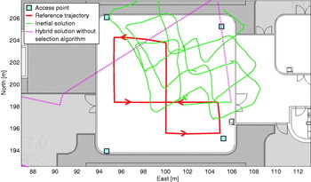
Figure 11. Detail of Figure 10.
As expected, the hybrid solution performs better than the inertial only solution. This performance difference is even stronger when the hybrid trajectory is computed without using any selection algorithm. Even if the scale of Figure 10 is not adequate to observe the entire footpath, it is interesting to notice that without any selection method, the solution diverges drastically. The trajectory leaves the room rapidly and sometimes reaches positions located up to several hundred metres away from the reference route.
Figures 12–14 depict the last analysis for all scenarios. The planimetric errors between the hybrid positions and the reference positions are computed at each waypoint (Equation 14). Errors of the MEMS based only trajectory are also represented. Planimetric errors of the solution computed without selection methods do not appear on these figures because their magnitude is too large.

Figure 12. Planimetric errors in scenario 1.

Figure 13. Planimetric errors in scenario 2.

Figure 14. Planimetric errors in scenario 3.
As expected, the coupling algorithm combines the advantages of both UWB and MEMS systems to improve the overall localisation performance. Except for the first scenario, the planimetric error of the hybrid positions remains under 2 metres with an average around 70 centimetres. This trend is lost when the positions are obtained without any selection method or only with MEMS data. In both cases, the planimetric error grows with time.
The major role of the implemented selection methods is highlighted through the comparison of the results obtained with and without selection. Without selection, reflected signals can drastically affect the AOA and TDOA measurements giving rise to large drifts. This proves that it is impossible to achieve reliable localisation performances without these selection methods.
7. CONCLUSIONS
This paper describes a novel pedestrian navigation solution based on the combination of UWB location and MEMS inertial data. First experimental results are very promising. The hybridised trajectories show a significant improvement, in terms of accuracy and reliability, compared with the performance of each technology considered alone. Generally, a 1 metre accuracy is achieved. This addresses the pedestrian's needs for reliable indoor localisation.
In order to achieve good localisation performance, specific selection methods for the UWB measurements are required. These reduce the effect of multipath phenomena, typical of an indoors environment. Implemented methods have been able to identify and reject the majority of the biased measurements.
According to the results presented in this paper, working on outlier selection methods might be a key to improve indoor navigation performance. The two following ideas are worthy of further investigation:
The cohesion and the number of geometrical intersections computed at a specific instant with all AOA and TDOA available, informs us about the presence of multipath.
If a lot of reflections come from clearly defined objects, such as the walls in a room, multipath prediction models could be used to distinguish them from line of sight measurements. Such methods should improve hybridisation performances.
Even though good results have been obtained, pedestrian navigation indoors remains a challenge.


