Introduction
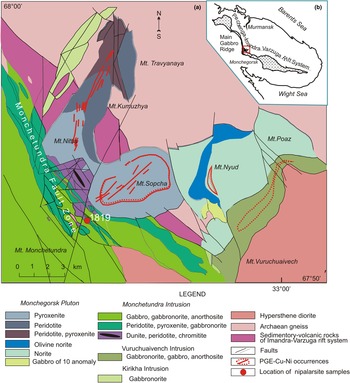
Nipalarsite, Ni8Pd3As4, is a new platinum-group mineral (PGM) species discovered in specimen from the Monchetundra layered Intrusion, Kola Peninsula, Russia. The mineral was found in a drill core taken from the borehole 1819 (67°52′22″N, 32°47′60″E) at the depth of 101.3–101.4 m. The mineral was discovered initially as anhedral grains (5–80 µm in size) in polished sections from the bulk sample 1819074 (Grokhovskaya et al., Reference Grokhovskaya, Lapina and Mokhov2009, fig. 3a, c–e). It was described preliminarily as an unnamed phase, Ni6Pd2As3, intergrown with other PGM (UM2003-40-As:NiPd, UM2009-02-As:NiPd, Grokhovskaya et al., Reference Grokhovskaya, Bakaev, Sholokhnev, Lapina and Muravitskaya2003, Reference Grokhovskaya, Lapina and Mokhov2009). A mineral with corresponding chemical composition [(wt.%: Pd 26, Ni 44.6, As 28, total 98.6, with an empirical formula (based on 15 atoms) of Ni8.27Pd2.66As4.07)] and XRD data [d, Å, I (%) (2.28 (3); 2.20 (4); 2.02 (10); 1.931 (3)] was also listed as an unnamed phase Pd2Ni6As3 (UM1986-As:NiPd) from massive cubanite–talnakhite ores of the Talnakh and Norilsk deposits, Russia (Genkin et al., Reference Genkin, Distler, Gladyshev, Filimonova, Evstigneeva, Kovalenker, Laputina, Smirnov and Grokhovskaya1981; Genkin and Evstigneeva, Reference Genkin and Evstigneeva1986). Previously, Gervilla et al. (Reference Gervilla, Makovicky, Makovicky and Rose-Hansen1994) reported, that it could represent a Ni-rich extension of the (Pd,Ni)8As3 solid-solution series, end-member of which is a mineral known as stillwaterite Pd8As3.
The name of the mineral corresponds to its chemical composition: Ni, Pd and As. Both the mineral and mineral name were approved by the Commission on New Minerals and Mineral Names, IMA (IMA2018-075, Grokhovskaya et al., Reference Grokhovskaya, Karimova, Vymazalová, Laufek, Chareev and Rassulov2018). The type material is deposited at the Fersman Mineralogical Museum, Russian Academy of Sciences, Leninsky Prospekt 18–2, Moscow 119071, Russia, registration number 5236/1.
The article describes the properties of the mineral and its geological occurrence, along with comments on its potential conditions of formation.
Geological setting, occurrence and associated minerals
The Early Palaeoproterozoic (2504.4 ± 1.5 to 2453 ± 4 Ma) layered intrusions of the Monchegorsk Igneous Complex are located within the southern inner corner of the Pasvic–Pechenga–Imandra–Varzuga rift-transform system (Amelin et al., Reference Amelin, Heaman and Semenov1995; Grokhovskaya et al., Reference Grokhovskaya, Bakaev, Sholokhnev, Lapina and Muravitskaya2003; Bayanova et al., Reference Bayanova, Nerovich, Mitrofanov, Zhavkov and Serov2010). The Monchegorsk Igneous Complex intrudes into gneisses of the Archaean Kola Group and is overlain by volcanics and clastics of Palaeoproterozoic Pechenga–Varzuga Series. The Monchegorsk Igneous Complex consists of the ‘Main Gabbro Ridge’ massif (including the Monche-, Chuna-, Volche- and Losevy-Tundra intrusions) striking NW to SE, and the Monchegorsk Pluton (Fig. 1a,b). Ultramafic cumulates prevail in the Monchegorsk Pluton whereas intrusions of Main Gabbro Ridge are composed mainly of mafic, and to a lesser extent of ultramafic cumulates.

Fig. 1. Simplified geological map of the Monchegorsk Igneous Complex showing the sample location (modified from Grokhovskaya et al., Reference Grokhovskaya, Bakaev, Sholokhnev, Lapina and Muravitskaya2003).
The Monchetundra layered intrusion consists of a lower ultrabasic zone of dunite, peridotite and pyroxenite (100–300 m thick); a middle zone of rhythmically layered pyroxenite, olivine pyroxenite, norite and gabbronorite (300–400 m thick), and an upper zone of gabbronorite and gabbro–anorthosite (800–1000 m thick). The reef-type platinum-group element (PGE) mineralisation (up to 3–5 ppm Pt + Pd) was discovered within a rhythmically layered zone (Grokhovskaya et al., Reference Grokhovskaya, Bakaev, Sholokhnev, Lapina and Muravitskaya2003; Reference Grokhovskaya, Lapina and Mokhov2009).
The Monchetundra intrusion and Monchegorsk Pluton join along the Monchetundra Regional Fault expressed by an extremely permeable shear-zone striking SE–NW. The Monchetundra Regional Fault consists of a lot of steeply dipping faulted slices represented by more- or less-altered rocks of the Monchetundra intrusion, ranging from dunite and peridotite, to pyroxenite, norite and gabbronorite. Low-sulfide PGE mineralisation is located in tectonised chromite-bearing peridotite, pyroxenite and norite, which features highly variable thicknesses (from 1 to 100 m) and PGE contents (from 1–3 to 20 ppm Pt + Pd). More than fifty PGM species have been found in this shear zone including nipalarsite (Grokhovskaya et al., Reference Grokhovskaya, Lapina and Mokhov2009).
The host rocks of the samples investigated are represented by orthopyroxene cumulates and consist of orthopyroxene, olivine, augite and plagioclase, sometimes totally replaced by anthophyllite, actinolite, Mg-hornblende, biotite–phlogopite-group and chlorite-group minerals with minor chromite, ilmenite and magnetite. Disseminated sulfides include pentlandite, violarite, heazlewoodite, chalcopyrite, chalcocite and pyrrhotite with some accessory minerals. The most common PGM are sperrylite, kotulskite, moncheite, merenskyite, isomertieite, telluropalladinite, keithconnite, hollingworthite, irarsite, stibiopalladinite, lukkulaisvaaraite, nipalarsite, menshikovite, telargpalite, monchetundraite, palarstanide, nielsenite and Cu3Pt, listed in approximate order of abundance. The electron-microprobe data associated with nipalarsite are given in Table 1.
Table 1 Electron-microprobe analyses of PGM associated with nipalarsite, Monchetundra layered intrusion

Abbreviations: Mer – merenskyite, Kot – kotulskite, Mon – moncheite, Mtt – monchetundraite, Tel – telargpalite, Lvt – lukkulaisvaaraite, Ism – isomertieite, Mnv – menshikovite, Pls - palarstanide, Nlt – nielsenite, Hlt – hollingworthite, Irt – irarsite, Spt – sperrylite; n.d – not detected; ‘–’ not analysed; apfu – atoms per formula unit.
Nipalarsite typically occurs as a part of complex polymineralic PGM intergrowths attached to pentlandite and enclosed in amphiboles and chlorite (Fig. 2a–f). Nipalarsite was found in polished sections and heavy-mineral concentrates ranging in size from 3.0 to 80 µm. It forms anhedral and subhedral grains intergrown with sperrylite, kotulskite, hollingworthite, isomertieite, palarstanide, monchetundraite and pentlandite (Fig. 2a,b).

Fig. 2. Reflected light (a) and back-scattered electron (b–f) images of nipalarsite (Npt) and associated minerals from the Monchetundra intrusion. (a, b) Association of nipalarsite, isomertieite (Ism), sperrylite (Spt), palarstanide (Pls) and kotulskite (Kot), replaced by monchetundraite (Mtt) and pentlandite (Pn); (c) two small grains of nipalarsite (used for EBSD analysis) intergrown with palarstanide embedded in anthophyllite (Anth); (d) nipalarsite (used for EBSD analysis), isomertieite and pentlandite replaced by chalcocite (Cc); (e) polyphase PGMs represented by nipalarsite, isomertieite, sperrylite and hollingworthite, attached to pentlandite enclosed in anthophyllite and chlorite (Chl); (f) association of nipalarsite with isomertieite, menshikovite (Mnv) and pentlandite (Pn); inset in the right corner – general view of polyphase intergrowth of nipalarsite with other PGMs.
The genetic link between nipalarsite and other PGM is not apparent: in some cases nipalarsite forms its own grains attached to pentlandite (Fig. 2a,e), after pentlandite (Fig. 2d), or in one case possibly menshikovite and pentlandite formed symplectites then replaced by nipalarsite, or menshikovite occurred after nipalarsite in a pentlandite matrix (Fig. 2f). An advanced deposition of pentlandite in relation to the PGM is indicated in Fig. 2e, as the pentlandite is fractured and its cracks do not propagate into the adjacent nipalarsite.
Physical and optical properties
Nipalarsite is opaque, with metallic lustre, and brittle. Its powder has a grey streak. In plane-polarised reflected light the mineral is light grey with a blue tinge; in intergrowths associated with sperrylite it has a lilac tint. Reflectance values of nipalarsite were measured in air using an MSFU-312 microspectrophotometer (LOMO, Russia) with a WTiC standard (R589 in air = 48.7%). Reflectance data for natural nipalarsite are given in Table 2 and illustrated in Fig. 3. Values of VHN20 fall between 400.5 and 449.2 kg.mm–2, with a mean value of 429.9 kg.mm–2, corresponding to a Mohs hardness of ~4. The density calculated on the basis of the empirical formula is 9.60 g.cm–3.

Fig. 3. Reflectance data for nipalarsite in air. The reflectance values (R, %) are plotted versus wavelength (λ, nm).
Table 2. Reflectance data (%) for nipalarsite in air.

The values required by the Commission on Ore Mineralogy are given in bold.
Chemical composition
Chemical analyses were performed with a Jeol 8200 electron probe microanalyser in wavelength dispersive spectroscopy (WDS) mode using an electron beam diameter focused to 1–2 µm, with an accelerating voltage of 20 kV and a beam current of 20 nA on the Faraday cup. Pure Ni, Pd, Pt, Au metals, and FeS2, CuFeS2, PbS, GaAs, Sb2S3 and AuTe2 were used as standards. Concentrations were quantified on the Kα lines for Cu, Fe, Ni; Lα lines for Au, Pd, Pt, As, Te, Sb; and Mα line for Pb.
Nipalarsite has a fairly constant composition, WDS analyses of representative grains are given in Table 3. The average result of 27 electron microprobe WDS analyses of nipalarsite is (wt.%): Ni 44.01, Pd 28.74, Fe0.32, Cu 0.85, Pt 0.01, Au 0.05, As 25.42, Sb 0.05, Te 0.39, total 99.85. The empirical formula (normalised to 15 atoms per formula unit) for nipalarsite is: (Ni8.10Fe0.06)Σ8.16(Pd2.94Cu0.18)Σ3.12(As3.68Te0.03)Σ3.71, ideally, Ni8Pd3As4, and for the synthetic analogue (average of nine analyses) is Ni8.20Pd2.80As4.00.
Table 3. Electron-microprobe analyses of nipalarsite and its synthetic analogue*.

* Notes: Prefix ‘gr.1’ denotes grain 1, the largest grain of nipalarsite intergrown with isomertieite, sperrylite, hollingworthite and pentlandite (see Fig. 2e); ‘gr.2’ – grain 2 used for XRD analysis Fig 2a,b; ‘gr.3’ – grain 3, nipalarsite studied with EBSD (Fig. 2c); ‘gr.5’ – grain 5, nipalarsite (studied with EBSD) intergrown with penlandite (Fig 2d); ‘Synth.’ – synthetic analogue Ni8Pd3As4, average of nine analyses on seven different grains. n.d. – not detected.
Synthetic analogue
Several grains of nipalarsite were extracted from the polished sections and examined using single-crystal X-ray diffraction. However, they behaved like aggregates of several grains, showed Debye–Scherrer rings and proved to be unsuitable for structural analysis. Therefore, a fragment of a single crystal of synthetic Ni8Pd3As4 was used for the structural study. The synthetic Ni8Pd3As4 phase was prepared using the evacuated silica glass tube method. Pure elements: palladium (99.95%), nickel (99.999%) and arsenic (99.999%) were used as starting materials for the synthesis. The evacuated tube with its charge was sealed and then annealed at 900°C for 7 days. After cooling in a cold-water bath, the charge was ground into powder in acetone using an agate mortar, and mixed thoroughly to homogenise. The pulverised charge was sealed in an evacuated silica-glass tube again and reheated at 350°C for 60 days. The experimental product was rapidly quenched in cold water.
X-ray crystallography
Single-crystal X-ray diffraction
A fragment of the synthetic analogue of Ni8Pd3As4 was examined using a Bruker Apex–II diffractometer equipped with a CCD detector (MoKα radiation). A total of 9957 reflections were collected. The data were integrated and corrected for Lorenz and polarisation effects by means of the Bruker SAINT program. A semi-empirical absorption correction was applied on the basis of intensities of equivalent reflections using SADABS (Sheldrick, Reference Sheldrick2008).
The crystal structure was solved via direct methods in the space group Fm ![]() $\bar{3}$m and refined to the final R factor of 0.0144 (for 175 unique observed reflections with |F| ≥ 2σF). All calculations were performed with SHELX programs (Sheldrick, Reference Sheldrick2015a,Reference Sheldrickb) in the framework of a WinGX software package (Farrugia, Reference Farrugia2012).
$\bar{3}$m and refined to the final R factor of 0.0144 (for 175 unique observed reflections with |F| ≥ 2σF). All calculations were performed with SHELX programs (Sheldrick, Reference Sheldrick2015a,Reference Sheldrickb) in the framework of a WinGX software package (Farrugia, Reference Farrugia2012).
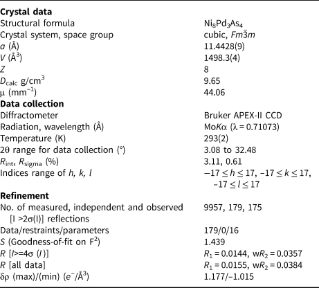
All atomic positions were located by direct methods and subsequently refined anisotropically. Inspection of the difference-Fourier map revealed that maximum positive and negative peaks were 1.177 and –1.015 e−/Å3, respectively. The refinement yielded a relatively short Pd–As3 distance of 2.3698 Å within the [As3Pd6] octahedra (see below). Refinement allowing the occupancy of As3 atom at the 4b position (½, ½, ½,) to vary showed no tendency of this atom to depart from the full occupancy. Refinement with the disordered As3 atom at the adjacent 24e position (x, ½, ½) resulted in unacceptably short Pd–As3 contacts and is considered as less probable than the model with As3 at the 4b position. Details of data collection, crystallographic data and refinement are in Table 4. Atomic coordinates and anisotropic displacement parameters are presented in Table 5, respectively and interatomic distances are given in Table 6.
Table 4. Crystal data and structure refinement for the synthetic analogue of nipalarsite.

w = 1/[σ2(F o2)+(0.0092P)2+41.4800P] where P = (F o2+2F c2)/3
Table 5. Atomic coordinates and equivalent isotropic and anisotropic displacement parameters (Å2) for the synthetic analogue of nipalarsite.

Table 6. Selected interatomic distances (Å) in the structure of the synthetic analogue of nipalarsite.

The crystallographic information files have been deposited with the Principal Editor of Mineralogical Magazine and are available as Supplementary material (see below).
Powder X-ray diffraction
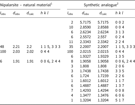
Powder X-ray diffraction data of nipalarsite (Table 7) were obtained from an isolated grain (Fig. 2b) using a Rigaku R-AXIS Rapid II diffractometer equipped with a cylindrical image plate detector, in Debye–Scherrer geometry (d = 127.4 mm; CoKα radiation). The data were integrated using the software package OSC2XRD (Britvin et al., Reference Britvin, Dolivo-Dobrovolsky and Krzhizhanovskaya2017). As only a few reflections were detected the unit-cell refinement was performed on the synthetic material.
Table 7. Powder X-ray diffraction data (d in Å) obtained from nipalarsite and its synthetic analogue.

1Obtained by Rigaku R-AXIS Rapid II diffractometer equipped with a cylindrical image plate detector, Debye-Scherrer geometry (d = 127.4 mm; CoKα radiation).
2Powder diffractometer in Bragg-Brentano geometry, CuKα radiation.
Powder X-ray diffraction data of the synthetic analogue of nipalarsite were collected on a Bruker D8 Advance diffractometer using CuKα radiation and the LynxEye XE detector in Bragg–Brentano geometry. The data were indexed by means of the structure model derived from the single-crystal diffraction data (see above). The unit-cell refinement was performed by the CelRef program (Laugier and Bochu, Reference Laugier and Bochu2003), yielding refined unit-cell parameters of a = 11.4352(6) Å and V = 1495.3 Å3.
Description of the crystal structure
The crystal structure of nipalarsite (Fig. 4) contains two Ni atom positions (both at Wyckoff position 32f), one Pd atom position (Wyckoff 24e), and three As atom positions (Wyckoff 4a, 24d and 4b). This yields 120 atoms within a unit-cell and the formula Ni8Pd3As4 for Z = 8.

Fig. 4. Crystal structure of nipalarsite showing the edge-sharing framework of [Ni8As10] supertetrahedra. The [As3Pd6] octahedra are emphasised.
As is typical for intermetallic phases, the nipalarsite crystal structure is characterised by atoms with complex coordination environments and high coordination numbers. Ni1 is coordinated by 13 atoms (4 As, 7 Ni and 3 Pd), while the Ni2 atom has a coordination number of 12 (3 As, 6 Ni and 3 Pd). Ni1–As distances are in the range 2.3309–2.5301 Å. Ni2–As distances are equal to 2.3358 Å. Ni–Ni distances vary between 2.5988 Å and 2.7280 Å. Pd atoms show 4 + 4 Ni contacts at distances of 2.7231 Å and 2.7650 Å, respectively. The Pd coordination is completed by three As2 atoms at 2.9025 Å and a short distance to the As3 site (2.3698 Å).
The crystal structure of nipalarsite can be considered as a stuffed derivative of the Mg6Cu16Si7 structure type (Bergmann and Waugh, Reference Bergman and Waugh1956), which is also referred to as the Th6Mn23 structure type in the Inorganic Crystal Structure Database (Fachinformationszentrum Karlsruhe, 2018). Considering this relation, the nipalarsite chemical composition can be expressed as Pd6Ni16As7As1 (for Z = 4), which is directly comparable to that of Mg6Cu16Si7(□), where □ = vacancy. In nipalarsite, As3 atoms occupy the 4b position of the space group Fm ![]() $\bar{3}$m. This position is empty in the Mg6Cu16Si7 structure type.
$\bar{3}$m. This position is empty in the Mg6Cu16Si7 structure type.
Nipalarsite is an intermetallic phase and its structural arrangement is not easy to visualise. As was mentioned by Holman et al. (Reference Holman, Morosan, Casey, Li, Ong, Klimczuk, Felser and Cava2008) for synthetic phases with the Mg6Ni16Si7 structure type, such structures can be described conveniently in terms of large intermetallic polyhedra. The nipalarsite structure contains a cluster of eight Ni atoms formed from two interpenetrating Ni4 tetrahedra (Fig. 5a). As is indicated in Fig. 5b, this cluster is subsequently surrounded by 10 As atoms forming the [Ni8As10] supertetrahedra, which can be selected as a basic structural motive used for a structural description. The nipalarsite structure can be then viewed as an edge-sharing framework of the [Ni8As10] supertetrahedra (Fig. 4). An important feature of this structural arrangement is the presence of large structural cavities. These cavities contain the Pd6 octahedra with As3 atoms at their centres. The Pd–As3 distance of 2.3698 Å in this regular [As(3)Pd6] octahedra is slightly shorter than similar Pd–As contacts in Pd-bearing arsenides (e.g. 2.425 Å in PdAs2, Furuseth et al., Reference Furuseth, Selte and Kjekshus1967), however it seems to be a feature of the nipalarsite structure. Similar short bonding distances were observed in crystal structures of polar intermetallic phases (e.g. Ca–Ca in CaAu3Ga, Lin and Corbett, Reference Lin and Corbett2008; Ag–Ag in AgPd3Se, Laufek et al., Reference Laufek, Vymazalova, Chareev, Kristavchuk, Lin, Drahokoupil and Vasilchikova2011), very likely to be because of the matrix effect of surrounding atoms. The filler atoms do not have enough space to expand the network and hence short bonds occur.

Fig. 5. Detailed view of (a) the Ni8 cluster and (b) the [Ni8As10] supertetrahedra in the nipalarsite crystal structure.
Nipalarsite does not have a structural analogue in the mineralogical system. From a chemical point of view, the most related minerals are majakite, PdNiAs, (Evstigneeva et al., Reference Evstigneeva, Kabalov and Schneider2000) and menshikovite, Pd3Ni2As3 (Barkov et al., Reference Barkov, Martin, Pakhomovsky, Tolstykh and Krivenko2002). The majakite structure is based on [PdAs5] square pyramids and [NiAs4] distorted tetrahedra, the nipalarsite structure is typical for intermetallic compounds with high coordination numbers and hence is very different from that of majakite. The crystal structure of menshikovite is not known.
Relation of nipalarsite to synthetic Ni8Pd3As4
The structural identity of the natural and synthetic phase was confirmed by electron back-scattered diffraction (EBSD) measurements on the natural sample (grains in Fig. 2c,d) and comparison of X-ray diffraction data obtained from natural and synthetic Ni8Pd3As4.
The collected diffraction data from natural nipalarsite fit very well to those of synthetic Ni8Pd3As4 (Table 7). Moreover, the EBSD patterns (also known as Kikuchi patterns) derived from the crystal structure of Ni8Pd3As4 phase, fit very well to the measured patterns obtained from the natural grains of nipalarsite. The natural sample was prepared for investigation by etching the mechanically polished surface with colloidal silica (OP-U) for 15 min. to reduce the surface damage. The EBSD patterns were collected and processed using the proprietary computer program AZtec HKL (Oxford Instruments). The values of the mean angular deviation (MAD, i.e. goodness of fit of the solution) between the calculated and measured Kikuchi bands range between 0.53° and 0.39°. These values reveal a very good match; as long as values of mean angular deviation are <1, they are considered as indicators of an acceptable fit. A TESCAN Mira 3GMU scanning electron microscope combined with an EBSD system (Nordlys Nano detector, Oxford Instruments) was used for the measurements. The solid angles calculated from the patterns were compared with a structural model proposed match containing 90 reflectors to index the patterns. The EBSD patterns obtained from the natural material (18 measurements on different spots on natural nipalarsite) were found to match the patterns generated from our structural model (Fig. 6).

Fig. 6. EBSD image of natural nipalarsite; in the right pane, the Kikuchi bands are indexed.
Genetic implications and conclusions
Nipalarsite was found in association with other PGMs, disseminated sulfides and hydrous silicates in the intercumulus of orthopyroxene and plagioclase. It crystallised in intergrowths with isomertieite, hollingworthite, other PGMs and pentlandite. In some cases, nipalarsite replaces symplectites of menshikovite and pentlandite.
The Pd–Ni–As system was studied experimentally at 450°C and 790°C by Gervilla et al. (Reference Gervilla, Makovicky, Makovicky and Rose-Hansen1994). The existence of many binary and only two ternary compounds was established at 450°C, PdNiAs (majakite) and Pd3Ni2As3 (menshikovite). Nipalarsite was not observed at 450°C or at higher temperatures investigated by Gervilla et al. (Reference Gervilla, Makovicky, Makovicky and Rose-Hansen1994). It is likely that the solid solution of stillwaterite (Pd8As3) dissolving Ni (observed by Gervilla et al., Reference Gervilla, Makovicky, Makovicky and Rose-Hansen1994) breaks down at lower temperatures and nipalarsite is formed. The synthetic analogue of nipalarsite was synthesised for this study at 350°C. Apparently its temperature of formation is lower than that of majakite and menshikovite, which is confirmed by the mineral association, where menshikovite and pentlandite form symplectites replaced by nipalarsite. Consequently, the proposed new mineral was probably formed in post magmatic, hydrothermal conditions at lower temperatures, equal or below 350°C. However, its occurrence at higher temperatures under different thermodynamic conditions is not excluded.
Supplementary material
To view supplementary material for this article, please visit https://doi.org/10.1180/mgm.2019.70
Acknowledgements
The authors acknowledge Ulf Hålenius, Chairman of the CNMNC and its members for helpful comments on the submitted data. Constructive comments made by Louis J. Cabri, Andrei Barkov, an anonymous reviewer and Structures Editor Peter Leverett are greatly appreciated; they improved the quality of the manuscript. The editorial handling by Stuart Mills is also acknowledged. We thank Dr. A.A. Zolotarev (XRD Center of the St. Petersburg State University) for the help in collection of the single-crystal XRD data. This study was supported by the Russian Academy of Sciences, Program of Fundamental Research and by the Grant Agency of the Czech Republic (Project no. 18-15390S to AV). The work of DAC is supported by Act 211 Government of the Russian Federation, agreement No.02.A03.21.0006 and is performed according to the Russian Government Program of Competitive Growth of Kazan Federal University.


