


1 Introduction
A steadily rotating wing at a constant angle of attack has been considered to be a simplified model of the propulsion system of an insect-inspired flapping-wing micro air vehicle (FWMAV). For insect wings, the flapping motion can be considered to be a combination of the rotational translation and flip motions. The instantaneous force on a wing during rotational translation is observed to be similar to that experienced by the same wing in pure rotation (Dickinson, Lehmann & Sane Reference Dickinson, Lehmann and Sane1999). The studies on rotating wings have also been motivated by the developments in single-winged aerial vehicles (monocopters), inspired by samaras (Low, Pheh & Foong Reference Low, Pheh and Foong2016), which use auto-rotation to assist seeds to travel as far as possible from their release point.
It has been established that the stable attachment of a leading-edge vortex (LEV) throughout a wing’s rotation is responsible for generating the high and stable lift on the wing (Maxworthy Reference Maxworthy1979; Ellington et al.
Reference Ellington, van den Berg, Willmott and Thomas1996; Lentink et al.
Reference Lentink, Dickson, Van Leeuwen and Dickinson2009). The LEV is formed as the flow separates at the leading edge of a wing (
 $\unicode[STIX]{x1D6FC}\sim 45^{\circ }$
). Jardin (Reference Jardin2017) has shown that the Coriolis acceleration enhances the outboard transport of vorticity through the LEV core, causing the LEV to remain stably attached to the wing surface. The LEV is spiral in structure, growing in size from the wing root to the wing tip. The LEV growth is constrained as it approaches the trailing edge, which, in turn, limits the aerodynamic forces generated by the LEV (Garmann & Visbal Reference Garmann and Visbal2014). The chord length,
$\unicode[STIX]{x1D6FC}\sim 45^{\circ }$
). Jardin (Reference Jardin2017) has shown that the Coriolis acceleration enhances the outboard transport of vorticity through the LEV core, causing the LEV to remain stably attached to the wing surface. The LEV is spiral in structure, growing in size from the wing root to the wing tip. The LEV growth is constrained as it approaches the trailing edge, which, in turn, limits the aerodynamic forces generated by the LEV (Garmann & Visbal Reference Garmann and Visbal2014). The chord length,
 $c$
, at a spanwise location determines the distance between the leading and the trailing edges at that location. Although the wing geometry can broadly be characterised by its aspect ratio (
$c$
, at a spanwise location determines the distance between the leading and the trailing edges at that location. Although the wing geometry can broadly be characterised by its aspect ratio (
 $A$
), which is the ratio of the wingspan (
$A$
), which is the ratio of the wingspan (
 $b$
) to the mean wing chord (
$b$
) to the mean wing chord (
 $\overline{c}$
), its shape can differ markedly based on the spanwise variation of its chord. Hence, it is interesting to investigate the optimisation of wing shape to maximise aerodynamic performance.
$\overline{c}$
), its shape can differ markedly based on the spanwise variation of its chord. Hence, it is interesting to investigate the optimisation of wing shape to maximise aerodynamic performance.
Many FWMAVs and monocopters involve wing shapes inspired by insects and samaras, for example, those reported by Yasuda & Azuma (Reference Yasuda and Azuma1997), Ulrich & Pines (Reference Ulrich and Pines2012) and Hassanalian, Throneberry & Abdelkefi (Reference Hassanalian, Throneberry and Abdelkefi2017). Some researchers (e.g. Keennon et al. Reference Keennon, Klingebiel, Won and Andriukov2012; Low et al. Reference Low, Pheh and Foong2016) have used rectangular and the modified hummingbird-wing planforms for their FWMAVs and monocopters, which may not be the best for achieving high aerodynamic performance. On the other hand, wing optimisation studies (e.g. Hassanalian et al. Reference Hassanalian, Throneberry and Abdelkefi2017) have used quasi-steady models to predict the aerodynamic forces and, hence, lacked an understanding of the impact of the unsteady forces. Moreover, these studies have not explored the influence of wing shapes on flow structures to a sufficient extent.
Ansari, Knowles & Zbikowski (Reference Ansari, Knowles and Zbikowski2008) have investigated various generic wing shapes and found reverse triangles and reverse semi-ellipses to have maximum lift among symmetric and asymmetric wings, respectively. Ellington (Reference Ellington1984) has used the Beta function to simplify the shapes observed in nature. He has characterised wing shapes by their non-dimensional radius of the
 $k$
th moment of inertia, defined by
$k$
th moment of inertia, defined by
 $\hat{r}_{k}^{k}=\int _{0}^{1}{\hat{c}}\hat{r}^{k}\text{d}\hat{r}$
, where
$\hat{r}_{k}^{k}=\int _{0}^{1}{\hat{c}}\hat{r}^{k}\text{d}\hat{r}$
, where
 ${\hat{c}}$
is the local wing chord normalised by the mean chord and
${\hat{c}}$
is the local wing chord normalised by the mean chord and
 $\hat{r}$
is the spanwise distance normalised by the wingspan. Ellington found that most insect wings obeyed the laws of wing shape,
$\hat{r}$
is the spanwise distance normalised by the wingspan. Ellington found that most insect wings obeyed the laws of wing shape,
 $\hat{r}_{2}=0.929(\hat{r}_{1})^{0.732}$
and
$\hat{r}_{2}=0.929(\hat{r}_{1})^{0.732}$
and
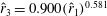 $\hat{r}_{3}=0.900(\hat{r}_{1})^{0.581}$
. However, the reasons for this conformity are unknown. Shahzad et al. (Reference Shahzad, Tian, Young and Lai2016) used these relations to generate various wing shapes. They showed an improvement in the mean lift coefficient (
$\hat{r}_{3}=0.900(\hat{r}_{1})^{0.581}$
. However, the reasons for this conformity are unknown. Shahzad et al. (Reference Shahzad, Tian, Young and Lai2016) used these relations to generate various wing shapes. They showed an improvement in the mean lift coefficient (
 $\overline{C}_{L}$
) with an increase in
$\overline{C}_{L}$
) with an increase in
 $\hat{r}_{1}$
. They designed wings of a constant
$\hat{r}_{1}$
. They designed wings of a constant
 $A$
to be of constant area and wingspan, thus having a constant disc loading. With an increase in
$A$
to be of constant area and wingspan, thus having a constant disc loading. With an increase in
 $\hat{r}_{1}$
, the area moved more outboard. The pressure distribution on their high-
$\hat{r}_{1}$
, the area moved more outboard. The pressure distribution on their high-
 $\hat{r}_{1}$
wing conformed more to the wing profile, suggesting that the wing loading is also important, in addition to the disc loading. However, the simplified shapes used in those studies may not be optimal.
$\hat{r}_{1}$
wing conformed more to the wing profile, suggesting that the wing loading is also important, in addition to the disc loading. However, the simplified shapes used in those studies may not be optimal.
Wing shapes may be optimised based on one or a combination of multiple factors including the lift coefficient, power economy, manoeuvrability, gender-related developmental constraints, dispersal or migration effects and requirement of the ability to autorotate, as can be seen in studies by Norberg (Reference Norberg1973) and Gilchrist et al. (Reference Gilchrist, Azevedo, Partridge and O’Higgins2000). In most cases, the lift coefficient is the dominant factor. Hence, a study of flow structures and the corresponding lift coefficients can provide useful insights into optimising wing planforms for MAVs. Interestingly, a recent study by Chen et al. (Reference Chen, Kolomenskiy, Nakata and Liu2018) indicates that insect forewing shape matches closely to the pressure contours on the wing surface under the LEVs. The wing-surface pressure can be directly related to the lift coefficient of the wing. However, no study appears to have employed the wing-surface pressure as a criterion for optimising wing shape.
In the present study, the use of an evolutionary approach has been proposed to systematically derive an optimised wing shape, simultaneously relating it to the effects on flow structures. This method has been inspired from the evolutionary structural optimisation typically used to optimise the designs of load-bearing structures. The evolutionary structural optimisation-based designs of load-bearing structures make an efficient use of building material to support the stresses in a structure. A similar method can be implemented in the case of a rotating wing to support the aerodynamic pressures on the wing surface. The problem considered corresponds to locally optimising lift-based performance for a wing of maximum span and constant flapping frequency, under the implied constraints that the chord cannot exceed the span and the leading edge remains straight. The first two constraints seem relevant to insects of a fixed size, thus restricting the span based on the folded wings, and under the constraint of constant flapping frequency. The optimisation process considers the evolutionary pressure to remove wing area that contributes little to the overall lift force. Our recent study (Bhat et al.
Reference Bhat, Zhao, Sheridan, Hourigan and Thompson2019) indicates that the pressure distribution on the wing surface varies with the Reynolds number. Hence, in the present computational study, various wing shapes are obtained from a generic rectangular wing at different Reynolds numbers, such that their areas support the surface pressures efficiently. Overall, the proposed method establishes a novel approach to optimise wing shapes at any given
 $Re$
to achieve a maximum lift coefficient.
$Re$
to achieve a maximum lift coefficient.
2 Methodology
The numerical method used in this study involves a model of a rotating wing, similar to that used in many studies of rotating and flapping wings (e.g. Garmann & Visbal Reference Garmann and Visbal2014; Kruyt et al. Reference Kruyt, van Heijst, Altshuler and Lentink2015; Limacher, Morton & Wood Reference Limacher, Morton and Wood2016). The flow over the wing has been simulated by solving the Navier–Stokes equations cast in a non-inertial reference frame along with the continuity constraint (see Harbig, Sheridan & Thompson Reference Harbig, Sheridan and Thompson2013; Bhat et al. Reference Bhat, Zhao, Sheridan, Hourigan and Thompson2018). The Navier–Stokes equations are solved directly using the commercial code ANSYS CFX version 17.2. The spatial and temporal discretisations were performed using second-order accurate schemes.
The model wing, having a span
 $b$
, mean chord
$b$
, mean chord
 $c$
and thickness
$c$
and thickness
 $0.01b$
, was placed at the centre of a cylindrical domain of diameter
$0.01b$
, was placed at the centre of a cylindrical domain of diameter
 $18b$
and length
$18b$
and length
 $48c$
, as has been validated by Harbig et al. (Reference Harbig, Sheridan and Thompson2013). The computational mesh for the domain was an unstructured tetrahedral mesh with triangular prism elements near the wing surface. The overall mesh consisted of approximately 10 million elements, with a grid spacing of
$48c$
, as has been validated by Harbig et al. (Reference Harbig, Sheridan and Thompson2013). The computational mesh for the domain was an unstructured tetrahedral mesh with triangular prism elements near the wing surface. The overall mesh consisted of approximately 10 million elements, with a grid spacing of
 $0.0145c$
on the wing surface. A time step of
$0.0145c$
on the wing surface. A time step of
 $0.00185T$
was chosen, where
$0.00185T$
was chosen, where
 $T$
is the total simulation time.
$T$
is the total simulation time.
The wing was maintained at a constant angle of attack (
 $\unicode[STIX]{x1D6FC}=45^{\circ }$
) throughout its rotation, which is typically used in most studies (e.g. Garmann & Visbal Reference Garmann and Visbal2014; Limacher et al.
Reference Limacher, Morton and Wood2016). It was initially accelerated over
$\unicode[STIX]{x1D6FC}=45^{\circ }$
) throughout its rotation, which is typically used in most studies (e.g. Garmann & Visbal Reference Garmann and Visbal2014; Limacher et al.
Reference Limacher, Morton and Wood2016). It was initially accelerated over
 $t=0.084T$
followed by a constant angular velocity (similar to Birch, Dickson & Dickinson (Reference Birch, Dickson and Dickinson2004) and Bhat et al. (Reference Bhat, Zhao, Sheridan, Hourigan and Thompson2018)), which corresponds to the span-based Reynolds number
$t=0.084T$
followed by a constant angular velocity (similar to Birch, Dickson & Dickinson (Reference Birch, Dickson and Dickinson2004) and Bhat et al. (Reference Bhat, Zhao, Sheridan, Hourigan and Thompson2018)), which corresponds to the span-based Reynolds number
 $$\begin{eqnarray}\displaystyle Re_{span}=U_{t}b/\unicode[STIX]{x1D708}, & & \displaystyle\end{eqnarray}$$
where
 $U_{t}$
is the velocity of the wing tip and
$U_{t}$
is the velocity of the wing tip and
 $\unicode[STIX]{x1D708}$
is the kinematic viscosity of the fluid. The length scale was chosen to be the wingspan
$\unicode[STIX]{x1D708}$
is the kinematic viscosity of the fluid. The length scale was chosen to be the wingspan
 $b$
, since Harbig et al. (Reference Harbig, Sheridan and Thompson2013) showed that the flow structure over a rotating wing of any
$b$
, since Harbig et al. (Reference Harbig, Sheridan and Thompson2013) showed that the flow structure over a rotating wing of any
 $A$
is quasi-similar if the span-based Reynolds number is maintained to be constant. Carr, DeVoria & Ringuette (Reference Carr, Devoria and Ringuette2015) have also confirmed this experimentally. It should be noted that the wing shape at a certain Reynolds number was optimised subject to constraints of a fixed wingspan and a fixed angular velocity, which are typically limited by the size and flapping-frequency constraints, respectively, of MAV wings. This resulted in a fixed wing-tip velocity (
$A$
is quasi-similar if the span-based Reynolds number is maintained to be constant. Carr, DeVoria & Ringuette (Reference Carr, Devoria and Ringuette2015) have also confirmed this experimentally. It should be noted that the wing shape at a certain Reynolds number was optimised subject to constraints of a fixed wingspan and a fixed angular velocity, which are typically limited by the size and flapping-frequency constraints, respectively, of MAV wings. This resulted in a fixed wing-tip velocity (
 $U_{t}$
), considered as the reference velocity throughout this study, as has also been done by Aono, Shyy & Liu (Reference Aono, Shyy and Liu2008), Carr et al. (Reference Carr, Devoria and Ringuette2015) and Han, Chang & Cho (Reference Han, Chang and Cho2015). Given the above constraints, the evolutionary method was employed to derive the wing shapes by maximising the lift per unit area (
$U_{t}$
), considered as the reference velocity throughout this study, as has also been done by Aono, Shyy & Liu (Reference Aono, Shyy and Liu2008), Carr et al. (Reference Carr, Devoria and Ringuette2015) and Han, Chang & Cho (Reference Han, Chang and Cho2015). Given the above constraints, the evolutionary method was employed to derive the wing shapes by maximising the lift per unit area (
 $L/S$
). Here, maximising
$L/S$
). Here, maximising
 $L$
can be a primary requirement for flying and minimising
$L$
can be a primary requirement for flying and minimising
 $S$
can result in the reduction in material required to manufacture a wing. The quantity
$S$
can result in the reduction in material required to manufacture a wing. The quantity
 $L/S$
can be non-dimensionalised as the lift coefficient, as explained later.
$L/S$
can be non-dimensionalised as the lift coefficient, as explained later.

Figure 1. Schematic of the rotating wing model and the pressure-contour-based wing cut.
The shape optimisation was initiated with a rectangular wing of unity aspect ratio. It has been observed that, as the wing rotates, the flow initially evolves until the rotation angle of
 $\unicode[STIX]{x1D719}\sim 90^{\circ }$
, past which it remains relatively stable (Bhat et al.
Reference Bhat, Zhao, Sheridan, Hourigan and Thompson2018). In the present study, the wing was rotated through
$\unicode[STIX]{x1D719}\sim 90^{\circ }$
, past which it remains relatively stable (Bhat et al.
Reference Bhat, Zhao, Sheridan, Hourigan and Thompson2018). In the present study, the wing was rotated through
 $270^{\circ }$
at
$270^{\circ }$
at
 $Re_{span}$
values of 520, 1732, 3465 and 6930, to determine the change in the optimised shapes with
$Re_{span}$
values of 520, 1732, 3465 and 6930, to determine the change in the optimised shapes with
 $Re_{span}$
. This range of
$Re_{span}$
. This range of
 $Re_{span}$
covers various insects, such as fruit flies and crane flies (Weis-Fogh Reference Weis-Fogh1973), and samaras such as those of the silver maple (Green Reference Green1980). The pressure contours on both sides of the wing were extracted at the end of the simulation. The difference in pressure between the sides contributes to the overall lift and drag acting on the wing. In the subsequent design step, the wing was cropped along a chosen pressure contour and the simulation was repeated with a new wing shape to observe the impact on the pressure distribution and overall aerodynamic force. A schematic of the wing and its coordinate system can be seen in figure 1. The evolutionary approach is elaborated in detail in § 3.2.
$Re_{span}$
covers various insects, such as fruit flies and crane flies (Weis-Fogh Reference Weis-Fogh1973), and samaras such as those of the silver maple (Green Reference Green1980). The pressure contours on both sides of the wing were extracted at the end of the simulation. The difference in pressure between the sides contributes to the overall lift and drag acting on the wing. In the subsequent design step, the wing was cropped along a chosen pressure contour and the simulation was repeated with a new wing shape to observe the impact on the pressure distribution and overall aerodynamic force. A schematic of the wing and its coordinate system can be seen in figure 1. The evolutionary approach is elaborated in detail in § 3.2.
3 Results
3.1 Leading-edge vortex and suction pressure
The LEV structure over a rotating wing is known to depend on the Reynolds number (Lentink & Dickinson Reference Lentink and Dickinson2009). At a higher
 $Re_{span}$
, the LEV is more compact with a higher spanwise vorticity flux. Since the LEV is responsible for the suction contributing to the overall lift, a change to the LEV structure with
$Re_{span}$
, the LEV is more compact with a higher spanwise vorticity flux. Since the LEV is responsible for the suction contributing to the overall lift, a change to the LEV structure with
 $Re_{span}$
can also affect the pressure distribution over the wing surface.
$Re_{span}$
can also affect the pressure distribution over the wing surface.
In the present study, the initially square wing was rotated at
 $Re_{span}=520$
and 6930. The resulting pressure distributions together with the LEV structures are shown in figure 2. High magnitude of suction pressure is present beneath the LEV structures, shown by transparent surfaces of constant
$Re_{span}=520$
and 6930. The resulting pressure distributions together with the LEV structures are shown in figure 2. High magnitude of suction pressure is present beneath the LEV structures, shown by transparent surfaces of constant
 $Q$
-criterion (Hunt, Wray & Moin Reference Hunt, Wray and Moin1988). Suction is increased at
$Q$
-criterion (Hunt, Wray & Moin Reference Hunt, Wray and Moin1988). Suction is increased at
 $Re_{span}=6930$
due to the increased surface proximity and spanwise transport of vorticity. At this
$Re_{span}=6930$
due to the increased surface proximity and spanwise transport of vorticity. At this
 $Re_{span}$
, the suction increase seems to be very sharp near the LEV boundary, highlighted as location (1) in the figure. However, at
$Re_{span}$
, the suction increase seems to be very sharp near the LEV boundary, highlighted as location (1) in the figure. However, at
 $Re_{span}=520$
, the increase in the magnitude of suction is more gradual. From this comparison, it may be inferred that, at a high
$Re_{span}=520$
, the increase in the magnitude of suction is more gradual. From this comparison, it may be inferred that, at a high
 $Re_{span}$
, the suction is concentrated over a smaller area. At
$Re_{span}$
, the suction is concentrated over a smaller area. At
 $Re_{span}=6930$
, a small region of vorticity at the wing root is transported diagonally towards the wing tip by the action of the increased Coriolis acceleration.
$Re_{span}=6930$
, a small region of vorticity at the wing root is transported diagonally towards the wing tip by the action of the increased Coriolis acceleration.

Figure 2. Wing suction pressure contours are shown for a wing of
 $A=1$
rotating at (a)
$A=1$
rotating at (a)
 $Re_{span}=520$
and (b)
$Re_{span}=520$
and (b)
 $Re_{span}=6930$
. At a high
$Re_{span}=6930$
. At a high
 $Re_{span}$
, the magnitude of suction changes abruptly at location (1). The semi-transparent surface shows the LEV structure identified using the constant
$Re_{span}$
, the magnitude of suction changes abruptly at location (1). The semi-transparent surface shows the LEV structure identified using the constant
 $Q$
-criterion. The small black dot represents the location of the wing root.
$Q$
-criterion. The small black dot represents the location of the wing root.
The net lift on a wing results from the difference between the pressures on the suction (
 $p_{s}$
) and pressure (
$p_{s}$
) and pressure (
 $p_{p}$
) sides. The pressures can be normalised as
$p_{p}$
) sides. The pressures can be normalised as
 $$\begin{eqnarray}\displaystyle p_{s}^{\ast }=p_{s}/(0.5\unicode[STIX]{x1D70C}U_{t}^{2})\quad \text{and}\quad p_{p}^{\ast }=p_{p}/(0.5\unicode[STIX]{x1D70C}U_{t}^{2}). & & \displaystyle\end{eqnarray}$$
The lift coefficient can be improved by maximising the pressure difference averaged over the wing area. This can be achieved by removing wing area where this difference is small. This method of material removal is similar to an evolutionary structural optimisation, such as that described by Xie & Steven (Reference Xie and Steven1997). However, here material was removed based on surface pressure, rather than von Mises stress relevant to structural optimisation. The approach is elaborated in the following section.
3.2 Evolution of wing shapes from pressure contours
Initially, the rectangular wing of
 $A=1$
was rotated at
$A=1$
was rotated at
 $Re_{span}=520,1732,3465$
and 6930. The normalised pressures on the wing suction side (
$Re_{span}=520,1732,3465$
and 6930. The normalised pressures on the wing suction side (
 $p_{s}^{\ast }$
) and the pressure side (
$p_{s}^{\ast }$
) and the pressure side (
 $p_{p}^{\ast }$
) were extracted. The criterion for material removal was chosen to be the difference
$p_{p}^{\ast }$
) were extracted. The criterion for material removal was chosen to be the difference
 $\unicode[STIX]{x0394}p^{\ast }=p_{p}^{\ast }-p_{s}^{\ast }$
, since it contributes to the lift coefficient. The comparison of
$\unicode[STIX]{x0394}p^{\ast }=p_{p}^{\ast }-p_{s}^{\ast }$
, since it contributes to the lift coefficient. The comparison of
 $p_{s}^{\ast }$
of the four different
$p_{s}^{\ast }$
of the four different
 $Re_{span}$
can be seen in figure 3(a–d), together with the comparison of
$Re_{span}$
can be seen in figure 3(a–d), together with the comparison of
 $p_{p}^{\ast }$
in figure 3(e,f). It is observed that the distribution of
$p_{p}^{\ast }$
in figure 3(e,f). It is observed that the distribution of
 $p_{s}^{\ast }$
changes with
$p_{s}^{\ast }$
changes with
 $Re_{span}$
. However, there is an insignificant change in
$Re_{span}$
. However, there is an insignificant change in
 $p_{p}^{\ast }$
. Note that the pressure acting on the wing edges is neglected as the wing thickness is very small (1 % of
$p_{p}^{\ast }$
. Note that the pressure acting on the wing edges is neglected as the wing thickness is very small (1 % of
 $b$
). The contours of
$b$
). The contours of
 $\unicode[STIX]{x0394}p^{\ast }$
are shown in figure 3(i–l).
$\unicode[STIX]{x0394}p^{\ast }$
are shown in figure 3(i–l).

Figure 3. The contours of
 $\unicode[STIX]{x0394}p^{\ast }$
(bottom row) are obtained by subtracting
$\unicode[STIX]{x0394}p^{\ast }$
(bottom row) are obtained by subtracting
 $p_{s}^{\ast }$
(top row) from
$p_{s}^{\ast }$
(top row) from
 $p_{p}^{\ast }$
(middle row) for
$p_{p}^{\ast }$
(middle row) for
 $Re_{span}=520$
, 1732, 3465 and 6930, in columns one to four, respectively. The black dot represents the position of the wing root and the black horizontal line (at the top of each panel) represents the leading edge. The coloured contours in the last row are superimposed with the black contour lines of constant rejection ratios.
$Re_{span}=520$
, 1732, 3465 and 6930, in columns one to four, respectively. The black dot represents the position of the wing root and the black horizontal line (at the top of each panel) represents the leading edge. The coloured contours in the last row are superimposed with the black contour lines of constant rejection ratios.
It can be seen that a high
 $\unicode[STIX]{x0394}p^{\ast }$
is concentrated in the region underneath the LEV, since it creates a large suction. A large area near the wing root and the trailing edge exerts a very low magnitude of pressure. Such inefficiently used material may be eliminated using a criterion for rejection, referred to as the rejection ratio,
$\unicode[STIX]{x0394}p^{\ast }$
is concentrated in the region underneath the LEV, since it creates a large suction. A large area near the wing root and the trailing edge exerts a very low magnitude of pressure. Such inefficiently used material may be eliminated using a criterion for rejection, referred to as the rejection ratio,
 $RR$
. Sections of the wing surface satisfying the following condition are removed from the model:
$RR$
. Sections of the wing surface satisfying the following condition are removed from the model:
 $$\begin{eqnarray}\displaystyle \frac{{\unicode[STIX]{x0394}p^{\ast }}_{mn}}{{\unicode[STIX]{x0394}p^{\ast }}_{max}}<RR_{i}, & & \displaystyle\end{eqnarray}$$
where the subscript
 $i$
denotes the design step number,
$i$
denotes the design step number,
 ${\unicode[STIX]{x0394}p^{\ast }}_{mn}$
is the value of
${\unicode[STIX]{x0394}p^{\ast }}_{mn}$
is the value of
 $\unicode[STIX]{x0394}p^{\ast }$
at a location of coordinates [
$\unicode[STIX]{x0394}p^{\ast }$
at a location of coordinates [
 $m,n$
] on the wing surface and
$m,n$
] on the wing surface and
 ${\unicode[STIX]{x0394}p^{\ast }}_{max}$
is the maximum value of
${\unicode[STIX]{x0394}p^{\ast }}_{max}$
is the maximum value of
 $\unicode[STIX]{x0394}p^{\ast }$
on the wing surface. The modified wing shapes are rotated at the same Reynolds numbers to evaluate the impact on the lift coefficients. In the subsequent design step (
$\unicode[STIX]{x0394}p^{\ast }$
on the wing surface. The modified wing shapes are rotated at the same Reynolds numbers to evaluate the impact on the lift coefficients. In the subsequent design step (
 $i+1$
), the initial rectangular wing is again cropped using a modified rejection ratio by introducing the evolutionary rate (
$i+1$
), the initial rectangular wing is again cropped using a modified rejection ratio by introducing the evolutionary rate (
 $ER$
), such that
$ER$
), such that
 $$\begin{eqnarray}\displaystyle RR_{i+1}=RR_{i}+ER,\quad i=1,2,3,\ldots & & \displaystyle\end{eqnarray}$$
In the present study, design steps are performed with the initial rejection ratio
 $RR_{1}=0.1$
and the evolutionary rate
$RR_{1}=0.1$
and the evolutionary rate
 $ER=0.1$
. To provide an overview of the various wing shapes that can be produced at different values of
$ER=0.1$
. To provide an overview of the various wing shapes that can be produced at different values of
 $RR$
, the contours of constant-
$RR$
, the contours of constant-
 $RR$
criteria are superimposed onto the colour map of
$RR$
criteria are superimposed onto the colour map of
 $\unicode[STIX]{x0394}p^{\ast }$
contours in figure 3(i–l). The wing planform in design step
$\unicode[STIX]{x0394}p^{\ast }$
contours in figure 3(i–l). The wing planform in design step
 $i$
was obtained by cropping the rectangular wing along the contour of
$i$
was obtained by cropping the rectangular wing along the contour of
 ${\unicode[STIX]{x0394}p^{\ast }}_{mn}/{\unicode[STIX]{x0394}p^{\ast }}_{max}=RR_{i}$
. In some cases, such as for
${\unicode[STIX]{x0394}p^{\ast }}_{mn}/{\unicode[STIX]{x0394}p^{\ast }}_{max}=RR_{i}$
. In some cases, such as for
 $RR_{4}=0.4$
, where the wing root was completely removed, the wingspan was reduced. To maintain a constant wingspan, the wing was provided with an extension using a small strip at the wing root, with a normalised chord
$RR_{4}=0.4$
, where the wing root was completely removed, the wingspan was reduced. To maintain a constant wingspan, the wing was provided with an extension using a small strip at the wing root, with a normalised chord
 $c_{p}/b=0.1$
. In all shapes, the origin was maintained to be at the centre of the chord at the wing root.
$c_{p}/b=0.1$
. In all shapes, the origin was maintained to be at the centre of the chord at the wing root.
3.3 Optimisation of wing shapes using the evolutionary approach
The original rectangular wing shape was modified by creating new planforms using the evolutionary method, as discussed in § 3.2. The modified planforms were also simulated to rotate at the same
 $Re_{span}$
as that of the rectangular wing. First, for
$Re_{span}$
as that of the rectangular wing. First, for
 $Re_{span}=520$
, the time traces of the lift (
$Re_{span}=520$
, the time traces of the lift (
 $L$
) were extracted and compared, as shown in figure 4. Here, the rejection ratio
$L$
) were extracted and compared, as shown in figure 4. Here, the rejection ratio
 $RR_{0}=0$
corresponds to the original rectangular planform. It can be seen that
$RR_{0}=0$
corresponds to the original rectangular planform. It can be seen that
 $L$
reaches a peak during the initial acceleration and then drops. Furthermore, after the rotation of approximately
$L$
reaches a peak during the initial acceleration and then drops. Furthermore, after the rotation of approximately
 $100^{\circ }$
,
$100^{\circ }$
,
 $L$
reaches a stable value due to the stable LEV, as also shown by Birch et al. (Reference Birch, Dickson and Dickinson2004) and Carr et al. (Reference Carr, Devoria and Ringuette2015). Hence, the mean lift (
$L$
reaches a stable value due to the stable LEV, as also shown by Birch et al. (Reference Birch, Dickson and Dickinson2004) and Carr et al. (Reference Carr, Devoria and Ringuette2015). Hence, the mean lift (
 $\overline{L}$
) can be obtained by averaging over the final
$\overline{L}$
) can be obtained by averaging over the final
 $30^{\circ }$
of rotation. It can be seen that
$30^{\circ }$
of rotation. It can be seen that
 $\overline{L}$
reduces with
$\overline{L}$
reduces with
 $RR$
due to a reduction in wing area. This reduction can be represented by the relative lift,
$RR$
due to a reduction in wing area. This reduction can be represented by the relative lift,
 $\overline{L}/\overline{L}_{0}$
, where
$\overline{L}/\overline{L}_{0}$
, where
 $\overline{L}_{0}$
is the mean lift over the rectangular wing at the same
$\overline{L}_{0}$
is the mean lift over the rectangular wing at the same
 $Re_{span}$
. Similarly, the wing area (
$Re_{span}$
. Similarly, the wing area (
 $S$
) relative to that of the rectangular wing (
$S$
) relative to that of the rectangular wing (
 $S_{0}$
) can be represented by
$S_{0}$
) can be represented by
 $S/S_{0}$
.
$S/S_{0}$
.

Figure 4. The time traces of
 $L$
are shown for the wing planforms obtained by rejection ratios
$L$
are shown for the wing planforms obtained by rejection ratios
 $RR_{2}=0.2$
(red),
$RR_{2}=0.2$
(red),
 $RR_{3}=0.3$
(green) and
$RR_{3}=0.3$
(green) and
 $RR_{4}=0.4$
(blue), rotating at
$RR_{4}=0.4$
(blue), rotating at
 $Re_{span}=520$
. The ratio
$Re_{span}=520$
. The ratio
 $RR_{0}$
(black) corresponds to the original rectangular planform.
$RR_{0}$
(black) corresponds to the original rectangular planform.
It can be seen in figure 5(a) that, even though
 $\overline{L}/\overline{L}_{0}$
on the wing is reduced with
$\overline{L}/\overline{L}_{0}$
on the wing is reduced with
 $RR$
, the relative area,
$RR$
, the relative area,
 $S/S_{0}$
, is reduced significantly more. This results in an improved mean lift coefficient, calculated as
$S/S_{0}$
, is reduced significantly more. This results in an improved mean lift coefficient, calculated as
 $$\begin{eqnarray}\displaystyle \overline{C}_{L}=\frac{\overline{L}}{0.5\unicode[STIX]{x1D70C}U_{t}^{2}S}. & & \displaystyle\end{eqnarray}$$
Here, the quantities
 $\unicode[STIX]{x1D70C}$
and
$\unicode[STIX]{x1D70C}$
and
 $U_{t}$
are maintained to be constant. Hence,
$U_{t}$
are maintained to be constant. Hence,
 $\overline{C}_{L}$
can be considered as a non-dimensional representation of
$\overline{C}_{L}$
can be considered as a non-dimensional representation of
 $\overline{L}/S$
. As shown in figure 5(b), the value of
$\overline{L}/S$
. As shown in figure 5(b), the value of
 $\overline{C}_{L}$
increases with
$\overline{C}_{L}$
increases with
 $RR$
, with the peak reached at
$RR$
, with the peak reached at
 $RR=0.3$
. Beyond
$RR=0.3$
. Beyond
 $RR=0.3$
,
$RR=0.3$
,
 $\overline{C}_{L}$
starts decreasing, indicating that
$\overline{C}_{L}$
starts decreasing, indicating that
 $RR=0.3$
gives the maximum lift coefficient at
$RR=0.3$
gives the maximum lift coefficient at
 $Re_{span}=520$
. Note that, in the evolutionary structural optimisation, the material is removed iteratively at any given
$Re_{span}=520$
. Note that, in the evolutionary structural optimisation, the material is removed iteratively at any given
 $RR_{i}$
, until the steady state is reached. On the contrary, in this evolutionary approach, only one cropping iteration is performed at a given
$RR_{i}$
, until the steady state is reached. On the contrary, in this evolutionary approach, only one cropping iteration is performed at a given
 $RR_{i}$
, since the pressures on the wings will get readjusted after rotating the cropped wing. After any iteration, there will always be some part of the wing area satisfying the condition in (3.2), and hence no steady state can be reached. Moreover, the incremental material removal at every iteration will require significantly more design changes and simulations, resulting in considerably more expensive computations. An example of such iterative process at
$RR_{i}$
, since the pressures on the wings will get readjusted after rotating the cropped wing. After any iteration, there will always be some part of the wing area satisfying the condition in (3.2), and hence no steady state can be reached. Moreover, the incremental material removal at every iteration will require significantly more design changes and simulations, resulting in considerably more expensive computations. An example of such iterative process at
 $Re_{span}=520$
is shown in figure 5(b). Here, the wing has been cropped iteratively at the steps
$Re_{span}=520$
is shown in figure 5(b). Here, the wing has been cropped iteratively at the steps
 $RR=0.1$
and
$RR=0.1$
and
 $RR=0.2$
. The reduction in the wing area relative to the original rectangular wing area (
$RR=0.2$
. The reduction in the wing area relative to the original rectangular wing area (
 $S_{0}$
) is shown by the quantity
$S_{0}$
) is shown by the quantity
 $\unicode[STIX]{x0394}S^{\ast }=(S-S_{0})/S_{0}$
. The improvement in
$\unicode[STIX]{x0394}S^{\ast }=(S-S_{0})/S_{0}$
. The improvement in
 $\overline{C}_{L}$
for
$\overline{C}_{L}$
for
 $RR=0.1$
follows a similar trend, initially, as in the non-iterative process, followed by a reduction in
$RR=0.1$
follows a similar trend, initially, as in the non-iterative process, followed by a reduction in
 $\overline{C}_{L}$
. Furthermore, for
$\overline{C}_{L}$
. Furthermore, for
 $RR=0.2$
, the improvement in
$RR=0.2$
, the improvement in
 $\overline{C}_{L}$
is less than 3 %. All the
$\overline{C}_{L}$
is less than 3 %. All the
 $\overline{C}_{L}$
values from these two
$\overline{C}_{L}$
values from these two
 $RR$
criteria are lower than
$RR$
criteria are lower than
 $RR=0.3$
. Hence, the maximum value of
$RR=0.3$
. Hence, the maximum value of
 $\overline{C}_{L}$
is indeed at
$\overline{C}_{L}$
is indeed at
 $RR=0.3$
, which can be obtained even with the faster non-iterative process.
$RR=0.3$
, which can be obtained even with the faster non-iterative process.

Figure 5. (a) At
 $Re_{span}=520$
, the stepwise design variations of the mean lift relative to that of the rectangular wing (
$Re_{span}=520$
, the stepwise design variations of the mean lift relative to that of the rectangular wing (
 $\overline{L}/\overline{L}_{0}$
), the wing areas relative to that of the rectangular wing (
$\overline{L}/\overline{L}_{0}$
), the wing areas relative to that of the rectangular wing (
 $S/S_{0}$
) and the normalised radii of the second moment of area (
$S/S_{0}$
) and the normalised radii of the second moment of area (
 $\hat{r}_{2}$
). (b) The variation of the mean lift coefficient (
$\hat{r}_{2}$
). (b) The variation of the mean lift coefficient (
 $\overline{C}_{L}$
). The variations in
$\overline{C}_{L}$
). The variations in
 $\overline{C}_{L}$
using the iterative cropping method at
$\overline{C}_{L}$
using the iterative cropping method at
 $RR=0.1$
and 0.2 have also been compared. (c) The spanwise variations in the sectional lift coefficient (
$RR=0.1$
and 0.2 have also been compared. (c) The spanwise variations in the sectional lift coefficient (
 $\text{d}\overline{C}_{L}/\text{d}r^{\ast }$
) for various
$\text{d}\overline{C}_{L}/\text{d}r^{\ast }$
) for various
 $RR$
.
$RR$
.
The improvement in
 $\overline{C}_{L}$
with
$\overline{C}_{L}$
with
 $RR$
can be attributed to the change in the spanwise distribution of pressure, which can be observed by evaluating the sectional lift coefficient (
$RR$
can be attributed to the change in the spanwise distribution of pressure, which can be observed by evaluating the sectional lift coefficient (
 $\text{d}\overline{C}_{L}/\text{d}r^{\ast }$
) along the wingspan. Here,
$\text{d}\overline{C}_{L}/\text{d}r^{\ast }$
) along the wingspan. Here,
 $r^{\ast }$
represents the radial location of a wing section normalised by the wingspan. Coefficient
$r^{\ast }$
represents the radial location of a wing section normalised by the wingspan. Coefficient
 $\text{d}\overline{C}_{L}/\text{d}r^{\ast }$
can be obtained at a spanwise section by integrating
$\text{d}\overline{C}_{L}/\text{d}r^{\ast }$
can be obtained at a spanwise section by integrating
 $\unicode[STIX]{x0394}p^{\ast }$
along the chord at that section. The spanwise variations in
$\unicode[STIX]{x0394}p^{\ast }$
along the chord at that section. The spanwise variations in
 $\text{d}\overline{C}_{L}/\text{d}r^{\ast }$
for various values of
$\text{d}\overline{C}_{L}/\text{d}r^{\ast }$
for various values of
 $RR$
are compared in figure 5(c). It can be seen that, with an increase in
$RR$
are compared in figure 5(c). It can be seen that, with an increase in
 $RR$
,
$RR$
,
 $\text{d}\overline{C}_{L}/\text{d}r^{\ast }$
reduces inboard and increases significantly outboard. The peak value of
$\text{d}\overline{C}_{L}/\text{d}r^{\ast }$
reduces inboard and increases significantly outboard. The peak value of
 $\text{d}\overline{C}_{L}/\text{d}r^{\ast }$
, seen roughly near
$\text{d}\overline{C}_{L}/\text{d}r^{\ast }$
, seen roughly near
 $r^{\ast }=0.9$
, decreases beyond
$r^{\ast }=0.9$
, decreases beyond
 $RR=0.4$
. Although the peak value for
$RR=0.4$
. Although the peak value for
 $RR=0.4$
is slightly higher than that for
$RR=0.4$
is slightly higher than that for
 $RR=0.3$
, the overall variation in
$RR=0.3$
, the overall variation in
 $\text{d}\overline{C}_{L}/\text{d}r^{\ast }$
at
$\text{d}\overline{C}_{L}/\text{d}r^{\ast }$
at
 $RR=0.4$
shows lower values throughout the span, except in the range
$RR=0.4$
shows lower values throughout the span, except in the range
 $0.8<r^{\ast }<0.95$
. Therefore,
$0.8<r^{\ast }<0.95$
. Therefore,
 $\overline{C}_{L}$
obtained for
$\overline{C}_{L}$
obtained for
 $RR=0.3$
is the highest.
$RR=0.3$
is the highest.
In general, the modified planforms obtained from the design evolution were found to have a significantly greater
 $\overline{C}_{L}$
than the rectangular wing. This process was repeated for different
$\overline{C}_{L}$
than the rectangular wing. This process was repeated for different
 $Re_{span}$
and the values of
$Re_{span}$
and the values of
 $\overline{C}_{L}$
were computed to determine the optimum
$\overline{C}_{L}$
were computed to determine the optimum
 $RR$
. The variation in
$RR$
. The variation in
 $\overline{C}_{L}$
with
$\overline{C}_{L}$
with
 $RR$
for various
$RR$
for various
 $Re_{span}$
is shown as a contour map in figure 6(a). It can be seen that, for any
$Re_{span}$
is shown as a contour map in figure 6(a). It can be seen that, for any
 $Re_{span}$
,
$Re_{span}$
,
 $\overline{C}_{L}$
reaches a maximum value at
$\overline{C}_{L}$
reaches a maximum value at
 $RR=0.3$
and starts decreasing beyond this ratio. Hence, optimised wing shapes can be obtained with
$RR=0.3$
and starts decreasing beyond this ratio. Hence, optimised wing shapes can be obtained with
 $RR=0.3$
across all Reynolds numbers. The values of
$RR=0.3$
across all Reynolds numbers. The values of
 $\overline{C}_{L}$
for these optimised wing shapes are plotted as a function of
$\overline{C}_{L}$
for these optimised wing shapes are plotted as a function of
 $Re_{span}$
in figure 6(b). The comparison with the values for the original rectangular wing at the same
$Re_{span}$
in figure 6(b). The comparison with the values for the original rectangular wing at the same
 $Re_{span}$
shows a remarkable 40 % improvement in
$Re_{span}$
shows a remarkable 40 % improvement in
 $\overline{C}_{L}$
. Moreover, the rotations of a fruit fly wing and of a bumblebee forewing were also simulated at various
$\overline{C}_{L}$
. Moreover, the rotations of a fruit fly wing and of a bumblebee forewing were also simulated at various
 $Re_{span}$
to compare their
$Re_{span}$
to compare their
 $\overline{C}_{L}$
values. It should be noted that the geometrical parameters of the optimised wings are different from those observed in nature, since there might be several other factors affecting the wing morphology, as discussed later. In fact, although the
$\overline{C}_{L}$
values. It should be noted that the geometrical parameters of the optimised wings are different from those observed in nature, since there might be several other factors affecting the wing morphology, as discussed later. In fact, although the
 $A$
values of the optimised wings do not match with those of the insect wings, they are within the optimum range of
$A$
values of the optimised wings do not match with those of the insect wings, they are within the optimum range of
 $A$
at the respective span-based Reynolds numbers shown in our recent work (Bhat et al.
Reference Bhat, Zhao, Sheridan, Hourigan and Thompson2019).
$A$
at the respective span-based Reynolds numbers shown in our recent work (Bhat et al.
Reference Bhat, Zhao, Sheridan, Hourigan and Thompson2019).

Figure 6. (a) The contours of
 $\overline{C}_{L}$
plotted on the plane of
$\overline{C}_{L}$
plotted on the plane of
 $RR$
and
$RR$
and
 $Re_{span}$
. (b) The variation of
$Re_{span}$
. (b) The variation of
 $\overline{C}_{L}$
plotted against
$\overline{C}_{L}$
plotted against
 $Re_{span}$
for the rectangular wing, optimised shapes at
$Re_{span}$
for the rectangular wing, optimised shapes at
 $RR=0.3$
and planforms of a fruit fly wing and a bumblebee wing. The optimised
$RR=0.3$
and planforms of a fruit fly wing and a bumblebee wing. The optimised
 $\overline{C}_{L}$
values are highlighted with black dots in (a) and the corresponding shapes are shown in grey colour in (b).
$\overline{C}_{L}$
values are highlighted with black dots in (a) and the corresponding shapes are shown in grey colour in (b).
Table 1. Characteristics of the wing shapes.

From figure 6(b), it is clear that the optimised wings have more area outboard. Hence, their centroids are further away from the wing root compared to a rectangular wing. The normalised radii of the first and second moment of inertia, i.e.
 $\hat{r}_{1}$
and
$\hat{r}_{1}$
and
 $\hat{r}_{2}$
, respectively, for various wings are summarised in table 1. This shows that the wings with a higher
$\hat{r}_{2}$
, respectively, for various wings are summarised in table 1. This shows that the wings with a higher
 $\hat{r}_{1}$
have a higher
$\hat{r}_{1}$
have a higher
 $\overline{C}_{L}$
. Interestingly, forewings of insects are found to have a larger area outboard and a recent study by Chen et al. (Reference Chen, Kolomenskiy, Nakata and Liu2018) shows that these wings provide most of the lift, whereas the hindwings mostly aid in manoeuvrability. The values of
$\overline{C}_{L}$
. Interestingly, forewings of insects are found to have a larger area outboard and a recent study by Chen et al. (Reference Chen, Kolomenskiy, Nakata and Liu2018) shows that these wings provide most of the lift, whereas the hindwings mostly aid in manoeuvrability. The values of
 $\hat{r}_{1}$
and
$\hat{r}_{1}$
and
 $\hat{r}_{2}$
for the bumblebee forewing are higher than those for the rectangular wing and the fruit fly wing and lower than those for the optimised wings and so is its
$\hat{r}_{2}$
for the bumblebee forewing are higher than those for the rectangular wing and the fruit fly wing and lower than those for the optimised wings and so is its
 $\overline{C}_{L}$
, consistent with the findings of Shahzad et al. (Reference Shahzad, Tian, Young and Lai2016). Therefore, in this case,
$\overline{C}_{L}$
, consistent with the findings of Shahzad et al. (Reference Shahzad, Tian, Young and Lai2016). Therefore, in this case,
 $\overline{C}_{L}$
can be considered to be artificially increased, since a larger percentage of the area of the cropped wings is subjected to higher velocities.
$\overline{C}_{L}$
can be considered to be artificially increased, since a larger percentage of the area of the cropped wings is subjected to higher velocities.
However, it must be noted that this relation between
 $\hat{r}_{1}$
,
$\hat{r}_{1}$
,
 $\hat{r}_{2}$
and
$\hat{r}_{2}$
and
 $\overline{C}_{L}$
is not always the same. For example, as shown in figure 5, the value of
$\overline{C}_{L}$
is not always the same. For example, as shown in figure 5, the value of
 $\hat{r}_{2}$
, for the wing shapes derived by increasing
$\hat{r}_{2}$
, for the wing shapes derived by increasing
 $RR$
, increases. However, the value of
$RR$
, increases. However, the value of
 $\overline{C}_{L}$
is decreased beyond
$\overline{C}_{L}$
is decreased beyond
 $RR=0.3$
, even if its
$RR=0.3$
, even if its
 $\hat{r}_{2}$
is increased. This is because
$\hat{r}_{2}$
is increased. This is because
 $\overline{C}_{L}$
is affected not only by
$\overline{C}_{L}$
is affected not only by
 $\hat{r}_{2}$
, but also by the change to the mean wing-surface pressure caused by the proximity of the trailing edge vortex after cropping. The increase in
$\hat{r}_{2}$
, but also by the change to the mean wing-surface pressure caused by the proximity of the trailing edge vortex after cropping. The increase in
 $\hat{r}_{2}$
contributes to an increase in
$\hat{r}_{2}$
contributes to an increase in
 $\overline{C}_{L}$
, whereas the proximity of the opposite sign vorticity from the trailing edge contributes to a decrease in the magnitude of the mean surface pressure, and hence to a decrease in
$\overline{C}_{L}$
, whereas the proximity of the opposite sign vorticity from the trailing edge contributes to a decrease in the magnitude of the mean surface pressure, and hence to a decrease in
 $\overline{C}_{L}$
. The distance
$\overline{C}_{L}$
. The distance
 $d_{LT}$
between the LEV and the trailing edge at a certain spanwise location can be obtained, as shown in figure 7(a). Here, the LEV has been identified using the constant
$d_{LT}$
between the LEV and the trailing edge at a certain spanwise location can be obtained, as shown in figure 7(a). Here, the LEV has been identified using the constant
 $Q$
-criterion and the spanwise location is chosen to be at
$Q$
-criterion and the spanwise location is chosen to be at
 $\hat{r}_{2}$
to allow comparison across various wing shapes. It can be seen in figure 7(b) that
$\hat{r}_{2}$
to allow comparison across various wing shapes. It can be seen in figure 7(b) that
 $d_{LT}/b$
reduces at the first design step and remains relatively stable until
$d_{LT}/b$
reduces at the first design step and remains relatively stable until
 $RR=0.3$
. On the other hand, there is an increase in
$RR=0.3$
. On the other hand, there is an increase in
 $\hat{r}_{2}$
with
$\hat{r}_{2}$
with
 $RR$
, which would increase
$RR$
, which would increase
 $\overline{C}_{L}$
. Beyond
$\overline{C}_{L}$
. Beyond
 $RR=0.3$
,
$RR=0.3$
,
 $d_{LT}/b$
is observed to drop while having no significant change to
$d_{LT}/b$
is observed to drop while having no significant change to
 $\hat{r}_{2}$
. Thus,
$\hat{r}_{2}$
. Thus,
 $\overline{C}_{L}$
is expected to decrease beyond
$\overline{C}_{L}$
is expected to decrease beyond
 $RR=0.3$
, which is consistent with our observations. Therefore, it is important to derive a wing profile such that the counteracting effects of
$RR=0.3$
, which is consistent with our observations. Therefore, it is important to derive a wing profile such that the counteracting effects of
 $\hat{r}_{2}$
and trailing edge proximity are optimised to achieve the maximum
$\hat{r}_{2}$
and trailing edge proximity are optimised to achieve the maximum
 $\overline{C}_{L}$
. The proposed evolutionary approach demonstrates the derivation of such optimum wing profile.
$\overline{C}_{L}$
. The proposed evolutionary approach demonstrates the derivation of such optimum wing profile.

Figure 7. (a) The minimum distance (
 $d_{LT}$
) between the LEV, shown by the blue contour, and the trailing edge (TE), is calculated at a spanwise section at
$d_{LT}$
) between the LEV, shown by the blue contour, and the trailing edge (TE), is calculated at a spanwise section at
 $\hat{r}_{2}$
. Here, the black line represents the wing cross-section with the leading edge shown by a filled circle and the trailing edge shown by a hollow circle. (b) The variation of the normalised distance
$\hat{r}_{2}$
. Here, the black line represents the wing cross-section with the leading edge shown by a filled circle and the trailing edge shown by a hollow circle. (b) The variation of the normalised distance
 $d_{LT}/b$
with changing
$d_{LT}/b$
with changing
 $RR$
for wings rotating at
$RR$
for wings rotating at
 $Re_{span}=520$
.
$Re_{span}=520$
.
As can be seen in figure 8, the wing-surface pressures are distributed more efficiently on the optimised wings than on a rectangular wing. At
 $Re_{span}=1732$
, 3465 and 6930, it can be seen that the wing shapes are just sufficient to support the LEV structures. Moreover, when compared to a rectangular wing, the magnitude of the suction pressure for the optimised wings has been slightly reduced by the action of the opposite sign vorticity from the trailing edge. This is because the trailing edge has moved closer to the leading edge in the inboard area of the wing. However, this reduced magnitude is insignificant compared to the increase in
$Re_{span}=1732$
, 3465 and 6930, it can be seen that the wing shapes are just sufficient to support the LEV structures. Moreover, when compared to a rectangular wing, the magnitude of the suction pressure for the optimised wings has been slightly reduced by the action of the opposite sign vorticity from the trailing edge. This is because the trailing edge has moved closer to the leading edge in the inboard area of the wing. However, this reduced magnitude is insignificant compared to the increase in
 $\overline{C}_{L}$
from eliminating a large amount of low-performing area. Furthermore, unlike for rectangular wings, a small amount of trailing-edge vorticity is also observed to tilt into the wake at a location of approximately 30 % of the span of the optimised wings. This may be due to the inability of the trailing-edge vortex to advect the vorticity along the trailing edge beyond a certain point. The trailing edge becomes nearly parallel to the chord at the midspan location, requiring the advection of the trailing-edge vorticity along the chordwise direction. The separation of this vorticity from the trailing edge might affect the suppression of the suction pressure, restoring a higher
$\overline{C}_{L}$
from eliminating a large amount of low-performing area. Furthermore, unlike for rectangular wings, a small amount of trailing-edge vorticity is also observed to tilt into the wake at a location of approximately 30 % of the span of the optimised wings. This may be due to the inability of the trailing-edge vortex to advect the vorticity along the trailing edge beyond a certain point. The trailing edge becomes nearly parallel to the chord at the midspan location, requiring the advection of the trailing-edge vorticity along the chordwise direction. The separation of this vorticity from the trailing edge might affect the suppression of the suction pressure, restoring a higher
 $\overline{C}_{L}$
.
$\overline{C}_{L}$
.

Figure 8. Normalised surface pressures on the optimised shapes (
 $RR=0.3$
) are distributed efficiently at (a)
$RR=0.3$
) are distributed efficiently at (a)
 $Re_{span}=520$
, (b)
$Re_{span}=520$
, (b)
 $Re_{span}=1732$
, (c)
$Re_{span}=1732$
, (c)
 $Re_{span}=3465$
and (d)
$Re_{span}=3465$
and (d)
 $Re_{span}=6930$
. The LEV structures are represented by the semi-transparent isosurfaces of constant
$Re_{span}=6930$
. The LEV structures are represented by the semi-transparent isosurfaces of constant
 $Q$
-criterion.
$Q$
-criterion.
Some studies (Lee, Lua & Lim Reference Lee, Lua and Lim2016; Jardin & Colonius Reference Jardin and Colonius2018) indicate that
 $\overline{C}_{L}$
is dependent on both the wing aspect ratio and Rossby number. Our recent study (Bhat et al.
Reference Bhat, Zhao, Sheridan, Hourigan and Thompson2019) has shown that, at a constant span-based Reynolds number,
$\overline{C}_{L}$
is dependent on both the wing aspect ratio and Rossby number. Our recent study (Bhat et al.
Reference Bhat, Zhao, Sheridan, Hourigan and Thompson2019) has shown that, at a constant span-based Reynolds number,
 $\overline{C}_{L}$
decreases with an increase in
$\overline{C}_{L}$
decreases with an increase in
 $A$
. Also,
$A$
. Also,
 $\overline{C}_{L}$
has been shown to decrease with an increase in the span-based Rossby number
$\overline{C}_{L}$
has been shown to decrease with an increase in the span-based Rossby number
 $Ro_{b}=r_{2}/b=\hat{r}_{2}$
. In the present case, as the wing is cropped, reducing the mean chord,
$Ro_{b}=r_{2}/b=\hat{r}_{2}$
. In the present case, as the wing is cropped, reducing the mean chord,
 $A$
and
$A$
and
 $\hat{r}_{2}$
are both simultaneously increased, which can cause a decrease in
$\hat{r}_{2}$
are both simultaneously increased, which can cause a decrease in
 $\overline{C}_{L}$
. However, with a constant rotation rate, the velocity at the radius of gyration is also increased, which can increase
$\overline{C}_{L}$
. However, with a constant rotation rate, the velocity at the radius of gyration is also increased, which can increase
 $\overline{C}_{L}$
. Therefore, a combined effect of these factors is observed, which might provide an additional explanation to the observed variation in
$\overline{C}_{L}$
. Therefore, a combined effect of these factors is observed, which might provide an additional explanation to the observed variation in
 $\overline{C}_{L}$
with
$\overline{C}_{L}$
with
 $RR$
.
$RR$
.
3.4 Effects on power economy
Although the main optimised parameter was the lift coefficient, or specifically the lift force per unit area, the impact of the derived optimal shapes on the power economy (
 $PE$
) was also investigated. The power economy is defined as the ratio of the mean lift coefficient and the mean power coefficient (
$PE$
) was also investigated. The power economy is defined as the ratio of the mean lift coefficient and the mean power coefficient (
 $PE=\overline{C}_{L}/\overline{C}_{P}$
), where the mean power coefficient is
$PE=\overline{C}_{L}/\overline{C}_{P}$
), where the mean power coefficient is
 $\overline{C}_{P}=(\overline{\unicode[STIX]{x1D70F}}_{y}\unicode[STIX]{x1D6FA})/(0.5\unicode[STIX]{x1D70C}U_{t}^{3}S)$
. Here,
$\overline{C}_{P}=(\overline{\unicode[STIX]{x1D70F}}_{y}\unicode[STIX]{x1D6FA})/(0.5\unicode[STIX]{x1D70C}U_{t}^{3}S)$
. Here,
 $\overline{\unicode[STIX]{x1D70F}}_{y}$
is the mean fluid mechanical torque acting along the axis of rotation and
$\overline{\unicode[STIX]{x1D70F}}_{y}$
is the mean fluid mechanical torque acting along the axis of rotation and
 $\unicode[STIX]{x1D6FA}$
is the constant angular velocity. The comparison of the values of
$\unicode[STIX]{x1D6FA}$
is the constant angular velocity. The comparison of the values of
 $PE$
for the optimised wing shapes at different Reynolds numbers with those for the rectangular wing is shown in figure 9(a). This demonstrates that the power economy of the optimised shapes is lower for any given Reynolds number than that for the rectangular wing. It is important to note that the improvement in
$PE$
for the optimised wing shapes at different Reynolds numbers with those for the rectangular wing is shown in figure 9(a). This demonstrates that the power economy of the optimised shapes is lower for any given Reynolds number than that for the rectangular wing. It is important to note that the improvement in
 $\overline{C}_{L}$
of the optimised wing shapes is huge (
$\overline{C}_{L}$
of the optimised wing shapes is huge (
 ${\sim}50\,\%$
) compared to the reduction in their
${\sim}50\,\%$
) compared to the reduction in their
 $PE$
(
$PE$
(
 ${\sim}15\,\%$
). The reduction in
${\sim}15\,\%$
). The reduction in
 $PE$
with increasing
$PE$
with increasing
 $\hat{r}_{1}$
is also in accordance with the results of Shahzad et al. (Reference Shahzad, Tian, Young and Lai2016). Interestingly, the fruit fly wing is observed to have
$\hat{r}_{1}$
is also in accordance with the results of Shahzad et al. (Reference Shahzad, Tian, Young and Lai2016). Interestingly, the fruit fly wing is observed to have
 $PE$
higher than that of the rectangular wing, even while having a similar
$PE$
higher than that of the rectangular wing, even while having a similar
 $\hat{r}_{1}$
. The reasons behind this difference were investigated further.
$\hat{r}_{1}$
. The reasons behind this difference were investigated further.

Figure 9. The variations of (a) power economy (
 $PE$
), (b)
$PE$
), (b)
 $\overline{C}_{L}/\overline{C}_{D}$
and (c) normalised location of the point of application of drag (
$\overline{C}_{L}/\overline{C}_{D}$
and (c) normalised location of the point of application of drag (
 $\hat{r}_{D}$
) with
$\hat{r}_{D}$
) with
 $Re_{span}$
are shown for the rectangular wing, optimised wing shapes and the fruit fly wing.
$Re_{span}$
are shown for the rectangular wing, optimised wing shapes and the fruit fly wing.
Wings with lower power economy require more power to overcome the mean torque
 $\overline{\unicode[STIX]{x1D70F}}_{y}$
. This torque is derived from the mean drag coefficient (
$\overline{\unicode[STIX]{x1D70F}}_{y}$
. This torque is derived from the mean drag coefficient (
 $\overline{C}_{D}$
) and the radial location of the centre of pressure. Here, both
$\overline{C}_{D}$
) and the radial location of the centre of pressure. Here, both
 $\overline{C}_{L}$
and
$\overline{C}_{L}$
and
 $\overline{C}_{D}$
directly depend on the wing-surface pressures. However, the ratio
$\overline{C}_{D}$
directly depend on the wing-surface pressures. However, the ratio
 $\overline{C}_{L}/\overline{C}_{D}$
increases with Reynolds number (Harbig et al.
Reference Harbig, Sheridan and Thompson2013), which might be responsible for the increase in
$\overline{C}_{L}/\overline{C}_{D}$
increases with Reynolds number (Harbig et al.
Reference Harbig, Sheridan and Thompson2013), which might be responsible for the increase in
 $PE$
with
$PE$
with
 $Re_{span}$
. To observe the effect of wing shape, the variation of
$Re_{span}$
. To observe the effect of wing shape, the variation of
 $\overline{C}_{L}/\overline{C}_{D}$
with
$\overline{C}_{L}/\overline{C}_{D}$
with
 $Re_{span}$
was plotted for different wings, as shown in figure 9(b). Although the optimised wings have lower
$Re_{span}$
was plotted for different wings, as shown in figure 9(b). Although the optimised wings have lower
 $\overline{C}_{L}/\overline{C}_{D}$
than the rectangular wing, the difference is less than 5 %. This implies that the increase in
$\overline{C}_{L}/\overline{C}_{D}$
than the rectangular wing, the difference is less than 5 %. This implies that the increase in
 $\overline{C}_{L}$
of the optimised wings is accompanied by an increase in
$\overline{C}_{L}$
of the optimised wings is accompanied by an increase in
 $\overline{C}_{D}$
by nearly an equal amount. Therefore, the significant contribution to the change in
$\overline{C}_{D}$
by nearly an equal amount. Therefore, the significant contribution to the change in
 $PE$
must be from the change in the moment arm. Hence, the variation of the normalised location of the point of application of drag (
$PE$
must be from the change in the moment arm. Hence, the variation of the normalised location of the point of application of drag (
 $\hat{r}_{D}=r_{D}/b$
) was plotted for different wings, as shown in figure 9(c). The optimised wings have higher
$\hat{r}_{D}=r_{D}/b$
) was plotted for different wings, as shown in figure 9(c). The optimised wings have higher
 $\hat{r}_{D}$
, which explains the increase in
$\hat{r}_{D}$
, which explains the increase in
 $\overline{C}_{P}$
. The fruit fly wing has the lowest
$\overline{C}_{P}$
. The fruit fly wing has the lowest
 $\hat{r}_{D}$
, and therefore the highest
$\hat{r}_{D}$
, and therefore the highest
 $PE$
. Decreasing
$PE$
. Decreasing
 $\hat{r}_{1}$
can further decrease
$\hat{r}_{1}$
can further decrease
 $\hat{r}_{D}$
to obtain even higher
$\hat{r}_{D}$
to obtain even higher
 $PE$
. Insect wings could have evolved to their present shapes as a result of a compromise between maximum lift coefficient and maximum power economy. There may be several other factors, such as the resistance to bending and resistance to torsion, which require a broader chord inboard (Ennos Reference Ennos1989; Wootton Reference Wootton1992). The evolution of insect wing morphology has also been affected by environmental factors and the requirement for thermo-regulation, as has been discussed by Kingslover & Koehl (Reference Kingslover and Koehl1994) and Johansson, Söderquist & Bokma (Reference Johansson, Söderquist and Bokma2009). It may be interesting to note that the forewings of insects like bumblebees have a larger area outboard, i.e. a high value of
$PE$
. Insect wings could have evolved to their present shapes as a result of a compromise between maximum lift coefficient and maximum power economy. There may be several other factors, such as the resistance to bending and resistance to torsion, which require a broader chord inboard (Ennos Reference Ennos1989; Wootton Reference Wootton1992). The evolution of insect wing morphology has also been affected by environmental factors and the requirement for thermo-regulation, as has been discussed by Kingslover & Koehl (Reference Kingslover and Koehl1994) and Johansson, Söderquist & Bokma (Reference Johansson, Söderquist and Bokma2009). It may be interesting to note that the forewings of insects like bumblebees have a larger area outboard, i.e. a high value of
 $\hat{r}_{1}$
, and their integral wings (forewing and hindwing together) have a lower
$\hat{r}_{1}$
, and their integral wings (forewing and hindwing together) have a lower
 $\hat{r}_{1}$
(Chen et al.
Reference Chen, Kolomenskiy, Nakata and Liu2018).
$\hat{r}_{1}$
(Chen et al.
Reference Chen, Kolomenskiy, Nakata and Liu2018).
Overall, it was observed that a higher
 $\overline{C}_{L}$
would require a larger area outboard. However, the value of
$\overline{C}_{L}$
would require a larger area outboard. However, the value of
 $\overline{C}_{D}$
would also increase simultaneously, as both the values depend on pressure. Hence, the power requirement to overcome the drag would also increase. One method of reducing the drag is to lower the angle of attack. However, it has been shown by Kruyt et al. (Reference Kruyt, van Heijst, Altshuler and Lentink2015) that lower angles are beneficial for the wings of very large
$\overline{C}_{D}$
would also increase simultaneously, as both the values depend on pressure. Hence, the power requirement to overcome the drag would also increase. One method of reducing the drag is to lower the angle of attack. However, it has been shown by Kruyt et al. (Reference Kruyt, van Heijst, Altshuler and Lentink2015) that lower angles are beneficial for the wings of very large
 $A$
(and at a high
$A$
(and at a high
 $Re_{span}$
). This is because, at a low
$Re_{span}$
). This is because, at a low
 $Re_{span}$
, lower angles of attack may create a smaller LEV, which would create a lower suction. Hence, the lift coefficient would also decrease, which is not desirable.
$Re_{span}$
, lower angles of attack may create a smaller LEV, which would create a lower suction. Hence, the lift coefficient would also decrease, which is not desirable.
Another method of reducing the power requirement is to lower the inertial torque that scales with
 $\hat{r}_{2}$
. For a simple flat plate planform, the radius of the second moment of area,
$\hat{r}_{2}$
. For a simple flat plate planform, the radius of the second moment of area,
 $\hat{r}_{2}(S)$
, is the same as that of the radius of mass moment of inertia,
$\hat{r}_{2}(S)$
, is the same as that of the radius of mass moment of inertia,
 $\hat{r}_{2}(m)$
. However,
$\hat{r}_{2}(m)$
. However,
 $\hat{r}_{2}(m)$
can be changed from
$\hat{r}_{2}(m)$
can be changed from
 $\hat{r}_{2}(S)$
by using a non-uniform thickness of the wing. Accordingly, the centre of mass can be shifted inward for the same planform by adding more mass to its root. The centre of pressure, which affects
$\hat{r}_{2}(S)$
by using a non-uniform thickness of the wing. Accordingly, the centre of mass can be shifted inward for the same planform by adding more mass to its root. The centre of pressure, which affects
 $\overline{C}_{L}$
and
$\overline{C}_{L}$
and
 $\overline{C}_{D}$
, is dependent on the spanwise wing area distribution, as seen in this study. Therefore, a larger
$\overline{C}_{D}$
, is dependent on the spanwise wing area distribution, as seen in this study. Therefore, a larger
 $\overline{C}_{L}$
can be obtained by more outwards wing area. Simultaneously, a lower inertial torque will be required to rotate or flap the wing when the centre of mass is moved inward using a thicker wing root. Interestingly, it can be seen that insect wings have a thick axillary area at the wing root, where all the wing venation is connected. The veins are thinner towards the tip, helping
$\overline{C}_{L}$
can be obtained by more outwards wing area. Simultaneously, a lower inertial torque will be required to rotate or flap the wing when the centre of mass is moved inward using a thicker wing root. Interestingly, it can be seen that insect wings have a thick axillary area at the wing root, where all the wing venation is connected. The veins are thinner towards the tip, helping
 $\hat{r}_{2}(m)$
to be located more inward. Such design may help the wings to have a larger
$\hat{r}_{2}(m)$
to be located more inward. Such design may help the wings to have a larger
 $\overline{C}_{L}$
and a lower
$\overline{C}_{L}$
and a lower
 $\overline{C}_{P}$
simultaneously.
$\overline{C}_{P}$
simultaneously.
Autorotating samaras do not require an internal power. The force driving their motion is provided by gravity. However, they require some additional features, such as a spanwise twist in the wing, to be able to autorotate. The twist helps in initiating the autorotation by providing an asymmetric resistance to the air flow when the seed starts falling (Norberg Reference Norberg1973). It also creates a uniform induced flow along the span, which is beneficial for the uniform distribution of the aerodynamic forces (Low et al.
Reference Low, Pheh and Foong2016). Moreover, the leading edge of a samara wing is tilted slightly down at its root. The angle made by the leading edge with the horizontal plane is called the coning angle,
 $\unicode[STIX]{x1D6FD}$
. A low and critical value of
$\unicode[STIX]{x1D6FD}$
. A low and critical value of
 $\unicode[STIX]{x1D6FD}$
is maintained to be constant when the low, radially inward aerodynamic force is balanced by the centrifugal force (Norberg Reference Norberg1973). At a constant rotational velocity, the low centrifugal force can be achieved by adjusting the location of the centre of mass,
$\unicode[STIX]{x1D6FD}$
is maintained to be constant when the low, radially inward aerodynamic force is balanced by the centrifugal force (Norberg Reference Norberg1973). At a constant rotational velocity, the low centrifugal force can be achieved by adjusting the location of the centre of mass,
 $\hat{r}_{1}(m)$
, radially inward. Indeed, in samaras, the heavy seed at the root of its lightweight wing helps in maintaining the centre of mass close to the root (
$\hat{r}_{1}(m)$
, radially inward. Indeed, in samaras, the heavy seed at the root of its lightweight wing helps in maintaining the centre of mass close to the root (
 $0.1<\hat{r}_{1}(m)<0.2$
).
$0.1<\hat{r}_{1}(m)<0.2$
).
However, as mentioned earlier, the focus of the present study is the improvement in
 $\overline{C}_{L}$
, which is shown to be significantly higher for the optimised shapes. The relatively small reduction in
$\overline{C}_{L}$
, which is shown to be significantly higher for the optimised shapes. The relatively small reduction in
 $PE$
is noted as a secondary effect of this process.
$PE$
is noted as a secondary effect of this process.
4 Discussion
It should be noted that, in nature, several factors may contribute to evolved wing shapes. For example, power economy is also important for flights involving flapping wings. In the present study, with wings held at
 $\unicode[STIX]{x1D6FC}=45^{\circ }$
, the pressure distribution contributed to both lift and drag almost equally. Hence, even though the lift coefficient improved with the optimisation, the drag coefficient would also be increased, requiring a higher power coefficient to rotate the wing. The power input can be reduced by reducing the angle of attack, which increases the mean lift-to-drag ratio, or by reducing
$\unicode[STIX]{x1D6FC}=45^{\circ }$
, the pressure distribution contributed to both lift and drag almost equally. Hence, even though the lift coefficient improved with the optimisation, the drag coefficient would also be increased, requiring a higher power coefficient to rotate the wing. The power input can be reduced by reducing the angle of attack, which increases the mean lift-to-drag ratio, or by reducing
 $\hat{r}_{1}$
, which reduces the inertial torque. Insect wings employ different angles of attack, depending on the wing aspect ratio and Reynolds number (Kruyt et al.
Reference Kruyt, van Heijst, Altshuler and Lentink2015). Moreover, insect wings have a thick axillary area at the wing root, which reduces the value of
$\hat{r}_{1}$
, which reduces the inertial torque. Insect wings employ different angles of attack, depending on the wing aspect ratio and Reynolds number (Kruyt et al.
Reference Kruyt, van Heijst, Altshuler and Lentink2015). Moreover, insect wings have a thick axillary area at the wing root, which reduces the value of
 $\hat{r}_{1}$
. Other considerations include environmental factors and a requirement for thermo-regulation (Kingslover & Koehl Reference Kingslover and Koehl1994). Unlike flapping wings, samaras undergo autorotation under the action of gravity. For autorotation, wing shapes need a spanwise twist and a concentration of mass at their roots, discussed by Norberg (Reference Norberg1973) and Low et al. (Reference Low, Pheh and Foong2016).
$\hat{r}_{1}$
. Other considerations include environmental factors and a requirement for thermo-regulation (Kingslover & Koehl Reference Kingslover and Koehl1994). Unlike flapping wings, samaras undergo autorotation under the action of gravity. For autorotation, wing shapes need a spanwise twist and a concentration of mass at their roots, discussed by Norberg (Reference Norberg1973) and Low et al. (Reference Low, Pheh and Foong2016).
In the present study, the wings were designed to have a straight leading edge, whereas insect wings and samaras are found to have a slightly curved leading edge with a smooth transition to the wing tip. This might allow a smoother merging of the LEV and the tip vortex. Nevertheless, the evolutionary approach discussed here provides a basis to optimise wing shapes as a preliminary step. It can be further employed, in addition to considering other constraints, to optimise wing shapes according to required operating conditions or constraints. The present work demonstrates a capability of optimising wing shapes using this novel method, showing a significant increase in the lift coefficient.
5 Conclusions
Wing shape is an important parameter affecting the flight performance of MAVs. Many past studies of rotating wings, inspired from insects and samaras, have employed generic wing planforms. However, wing shapes can be optimised to improve their performance. Previous optimisation studies have used optimisation methods together with quasi-steady force prediction models. However, they have not fully explored the coupled influence of selected shapes on flow structures.
An evolutionary approach was implemented to optimise the shapes of rotating wings as Reynolds number was varied, using three-dimensional direct numerical simulations. The optimised shapes were efficient in their use of material to support the aerodynamic pressures. Mean lift coefficient of the wing (
 $\overline{C}_{L}$
) significantly improved in successive evolution steps. The artificial increase in
$\overline{C}_{L}$
) significantly improved in successive evolution steps. The artificial increase in
 $\overline{C}_{L}$
was partially due to the increased
$\overline{C}_{L}$
was partially due to the increased
 $\hat{r}_{2}$
. However, it was found to be limited by the increasing
$\hat{r}_{2}$
. However, it was found to be limited by the increasing
 $A$
, which limited the growth of the LEV, such that the maximum
$A$
, which limited the growth of the LEV, such that the maximum
 $\overline{C}_{L}$
was obtained for
$\overline{C}_{L}$
was obtained for
 $RR$
of 0.3. The optimised shapes showed a reasonable variation with Reynolds number. In general, optimised wings exhibited larger areas outboard. These shapes supported the LEV structures more efficiently than rectangular wings, often used in typical experimental and numerical models in studies of samara and insect-wing aerodynamics.
$RR$
of 0.3. The optimised shapes showed a reasonable variation with Reynolds number. In general, optimised wings exhibited larger areas outboard. These shapes supported the LEV structures more efficiently than rectangular wings, often used in typical experimental and numerical models in studies of samara and insect-wing aerodynamics.
Wing shapes of samaras and insects are likely to have evolved subject to several performance parameters, combined with biomechanical and environmental factors. However, the necessity of generating near-maximum lift coefficient is likely to be a common factor. The study demonstrates a new approach to optimise wing shape, primarily directed at maximising lift coefficient. It also takes into account the effects of the shape on flow structures. This approach could be extended to take account of other constraints to optimise wing shapes for small monocopters and FWMAVs.
Acknowledgements
The authors acknowledge a generous computing time allocation from the National Computational Infrastructure (NCI) and Pawsey Supercomputer Centre (Merit Grants n67 and d71), and support through the Australian Research Council (grant no. DP150102879).


