


The last several decades have seen a surge in available technologies for documenting spatial information on archaeological projects. Total stations have all but replaced everything else for recording point data (Dibble Reference Dibble1987; Kvamme et al. Reference Kvamme, Ernenwein and Markussen2006; McCoy and Ladefoged Reference McCoy and Ladefoged2009; McPherron Reference McPherron2005). GNSS technology is becoming less expensive and more accurate (Hill et al. Reference Hill, Limp, Casana, Laugier and Williamson2019; McCoy and Ladefoged Reference McCoy and Ladefoged2009; Roosevelt Reference Roosevelt2014). Terrestrial lidar scanning is an increasingly conventional form of data collection and analysis (Lerma et al. Reference Lerma, Navarro, Cabrelles and Villaverde2010; Opitz Reference Opitz, Opitz and Cowley2013), and photogrammetry via handheld and low-elevation aerial photography is almost indispensable (Douglass et al. Reference Douglass, Lin and Chodoronek2015; Hill et al. Reference Hill, Rowan and Kersel2014; Roosevelt et al. Reference Roosevelt, Cobb, Moss, Olson and Ünlüsoy2015). Simultaneously, the trend toward exclusively digital data collection or paperless archaeology is the new normal on many projects. Data generated from fieldwork are increasingly born digital and integrated in coherent workflows that tie together stratigraphic recording, artifact documentation, excavation notes, 3D modeling, sample collecting, and spatial analyses. The results include improved and streamlined data curation, data access, and postexcavation analyses (Forte Reference Forte2014; Olson et al. Reference Olson, Placchetti, Quartermaine and Killebrew2013; Roosevelt et al. Reference Roosevelt, Cobb, Moss, Olson and Ünlüsoy2015; for some critiques of the boom in digital approaches, see Averett et al. Reference Averett, Gordon and Counts2016). 3D point data collection often remains an obstacle for the efficient and integrated gathering of spatial data on archaeological projects. It is worth contemplating novel technological solutions that can improve both the efficiency of point data collection during archaeological fieldwork and the interpretive value of digital recording. The following is a brief introduction to one such technology—Indoor Positioning Systems (IPS), often called “indoor GPS.” A case study of the IPS system offered by Marvelmind (marvelmind.com) deployed at the Chalcolithic (4600–3600 BC) site of Horvat Duvshan, Israel, demonstrates the potential application of this technology to improve workflow practices for spatial data collection. The current state of IPS technology is promising but may not yet be field ready.
A POINT DATA BOTTLENECK
In an analog past, one common approach to recording 3D point data on archaeological excavations involved using a line level on a string that was tied to a reference mark with a known height and a local coordinate (often the southwest corner of an excavation unit). Anyone who required a 3D coordinate within the excavation unit could pull the string level, hold it against a plumb line positioned above the point, and then measure the X, Y, and Z distances with measuring tapes (Figure 1). The resulting 3D coordinates were entered in field notes. This process was not particularly accurate, quick, or easy to do without an extra pair of hands, but it is possible to set this system up anywhere necessary across large or discontinuous excavation areas. Consequently, it made 3D point data accessible to anyone who needed it, at all times.

FIGURE 1. (left to right) Madeline Duppenthaler, Wesam Esaid, Morag Kersel, and Emma McCullough-Stearns using a line level and tapes to measure a coordinate. (Photo by Y. Rowan, courtesy of the Eastern Badia Archaeological Project.)
Modern digital techniques are not so democratic and accessible. The two most common tools for digital 3D point data collection are more accurate but less easily accessible, and they are sometimes slower than this older analog approach. Total stations and GNSS technologies are still reasonably expensive and usually require a trained operator. In the case of total stations, instruments are expensive enough that projects often only have one available to support relatively large excavation areas. Although robotic total stations can make this a one-person operation, such machines are a relative rarity for excavations due to their price, so two operators are typically required. Similarly, although data can be output from a total station to either a tablet or computer in the field, data is more commonly gathered on board a total station or specialized data collector and then downloaded later. Typically, this results in a system in which a single total station operator collects a list of measured points that must be synched to a central database and the point data passed back to those who need it. Total station data collection also relies on the setup of the machine within a useful range of where it is needed and—in the case of large sites—this can require significant time costs in setting up, using, and taking down the system (Bissaro-Júnior et al. Reference Bissaro-Júnior, Ghilardi, Bueno, Manzoli, Adorni, Muniz, Guilherme, De Souza Filho, Negri and Hsiou2018; Gutiérrez et al. Reference Gutiérrez, Erny, Friedman, Godsey and Gradoz2016). Although total stations are significantly more accurate than the string method described above, they are often a chokepoint in the collection of data during excavation. There are new low-cost options to make accurate GNSS data more accessible and affordable for archaeological projects (Hill et al. Reference Hill2019). These devices, however, are still expensive enough that there may be few available on site, often with a single operator collecting point data that once again must be synched to a central database and then made accessible to the people who needed the original point data.
Although archaeological projects now commonly rely on 3D photogrammetry to record excavations from day to day or over a set interval, or to document finds, important context changes, and critical anthropogenic features, 3D photogrammetry workflows usually rely on underlying point data collection via ground control points (GCPs) for accurate georeferencing (Hill Reference Hill2019). Point data collection can still be a significant holdup in collecting and processing 3D photogrammetry data on site. Often, excavators wait for the point data specialist and later have to track down the required GCP coordinate data. Is there a better way?
INDOOR POSITIONING SYSTEMS?
A relatively new category of technology may open a door for making 3D point data more widely accessible on excavations. Sometimes called “indoor GPS,” Indoor Positioning Systems (IPS) are a category of hardware that can provide point positioning information without requiring access to the radio signals from remote GNSS satellite constellations, which are commonly blocked indoors. Multiple companies are actively developing and marketing new IPS systems, driven by two use cases: indoor robotics navigation, and the tracking of customers, merchandise, and assets for retailers and logistics companies (Amsters et al. Reference Amsters, Demeester, Stevens, Lauwers, Slaets, Cruvinel and Valente2019; Hwangbo et al. Reference Hwangbo, Kim, Lee and Kim2017; Jimenez et al. Reference Jimenez, Schwarzl and Martin2019).
Several competing companies offer IPS systems that rely on a variety of ranging technologies (Wi-Fi signals, Bluetooth, inertial sensors, etc.)—including systems from Sewio, Pozyx, Localino, Ubisense, and Here—which vary widely in cost, functionality, and reported accuracy. One of the currently most promising systems for archaeology is offered by Marvelmind (marvelmind.com). This IPS system uses ultrasonic sensors and time of flight (ToF) measurements with trilateration calculations to produce 3D location information. Critically, these systems are affordable (current price for a starter kit is $399 USD), they provide ±2 cm accuracy out of the box, and they can output a standard NMEA data stream (a widely used GNSS/GPS data standard) over USB, which can be parsed by many third-party software suites and hardware systems. The Marvelmind system can be georeferenced so that the NMEA data output provides real-world or local coordinates in real time.
The Marvelmind IPS system uses a series of static beacons (a minimum of four for 3D positioning) placed around the area to be measured. Each beacon can send and receive a continuous stream of hypersonic signals used for ranging. A radio modem connected to a PC acts as a central controller for the system, and then at least one beacon operates as a rover (called a “hedgehog” in the Marvelmind nomenclature). Each hedgehog receives the signals from all of the static beacons and sends this information to the central PC (Figure 2). The PC performs trilateration calculations to find the position of the hedgehog and then sends that information back to the hedgehog, which outputs this positioning data over USB to a tablet. The effective range for each beacon is 30 m, so each set of four beacons is limited to an area smaller than 30 × 30 m (Figure 3). The Marvelmind system is, however, highly scalable, given that additional static beacons (up to 250 per modem) can be added to the system to extend the range over larger and larger areas. These areas do not need to be contiguous. Additionally, although Marvelmind lists the out-of-the-box accuracy as ±2 cm, it is possible to configure the system to provide >1 cm accuracy by reducing the update rate below 8 Hz (Marvelmind Robotics Reference Robotics2021). The beacons are also configurable and flexible. Basic beacons have built-in batteries with significant battery life, and ruggedized beacons are available for outdoor conditions and can be powered over longer periods with external power sources.

FIGURE 2. Screenshot of the Marvelmind dashboard GUI, which runs the system and can be adjusted to set up georeferencing, control accuracy and update rate, and configure output. Green circles are stationary beacons; the blue circle is hedgehog location.
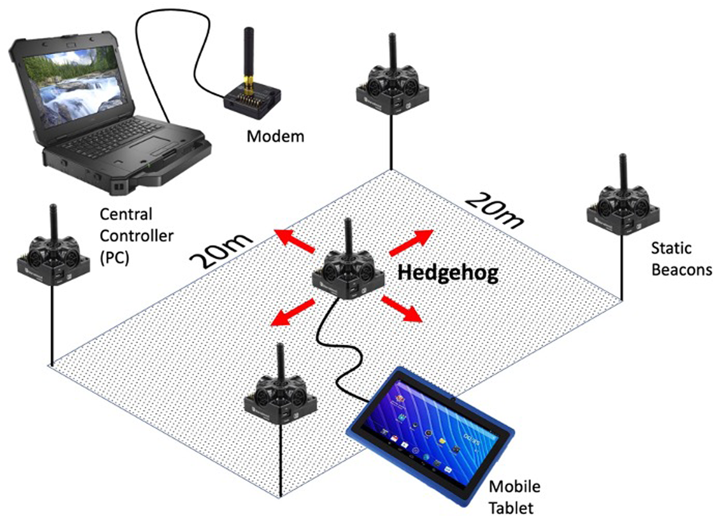
FIGURE 3. Schematic of Marvelmind layout for data collection (figure prepared by A. C. Hill).
This system does have some practical limitations that constrains functionality for archaeological field applications. This hardware is, as the term “indoor GPS” denotes, not primarily developed for outdoor work. One important drawback is the effect of wind on ultrasonic measurement. Although the system uses filters to reduce errors, winds that are strong enough will affect the accuracy of the system (Jimenez et al. Reference Jimenez, Schwarzl and Martin2019). Marvelmind asserts that errors due to wind are negligible at distances under 10–20 m and are only likely to affect further distances when winds are loud enough to be audible to humans. In practice, in the field, we noticed that the hedgehog position could begin to wander—from centimeters to tens of centimeters—at moderate wind speeds, particularly when it was gusty. This could definitely limit the practicality of relying on this technology in places where significant wind is a daily environmental condition, and it will require further testing.
Although the Marvelmind system was chosen for this test, based on the features described above, other systems may be fruitful for investigation and testing as well. The systems offered by Pozyx, for instance, have similar cost and accuracy claims. Their “Creator” system is aimed at hobbyists and will connect with common, low-cost Arduino or Raspberry Pi systems. Although this system does not, currently, seem to be able to output data in an NMEA stream the way the Marvelmind system does, experiments with coupling accurate GNSS data with Pozyx positioning data seem promising (Di Pietra et al. Reference Di Pietra, Dabove and Piras2020). Similarly, a recent article by Almeida-Warren and colleagues (Reference Almeida-Warren, Braun and Carvalho2021) investigates the archaeological utility of a related kind of low-cost device—the DistoX2—which couples a laser rangefinder fitted with a compass and clinometer, and it offers an additional alternative technological solution for environments where total stations and GNSS are not practical.
HOW DOES THIS HELP?
An always-on IPS system has several potential benefits over traditional point data collection systems for archaeological fieldwork. The most obvious is that it can work in GPS-denied environments, and it is more cost effective than a total station. In conditions such as rockshelters and cave sites, this might be an excellent alternative data collection solution. A continuous IPS system also has the capacity to provide widespread access to point data in any digital, paperless recording system. Once set up, the fact that the system can pass NMEA positioning data over USB to a computer or tablet means that the system acts as a direct replacement for almost any method that accepts external GPS data. This makes passing positioning data to third-party hardware and software relatively straightforward, including specialized database programs for archaeological field note recording (e.g., Smith et al. Reference Smith, Howland and Levy2015). Marvelmind also offers a software development kit (SDK) that would allow more direct incorporation into proprietary field recording software. Any user on site could have their own “hedgehog” attached to their data collection tablet and would be able to record accurate 3D coordinates into their data collection database in real time without relying on a specialist or a single piece of hardware (i.e., survey-grade GNSS or the total station operator and their prism pole). In large excavations, multiple hedgehogs could operate simultaneously so that any area, square, or trench supervisor; technical specialist; or data recorder could record 3D coordinates at all times. Coordinates are recorded as needed, and they would be accessible for importing directly into the tablet of each person collecting such things as photogrammetry photo sets. This would alleviate data collection bottlenecks for photogrammetry GCP recording.
POINT DATA VERSUS DIGITIZING
Another key difference between this sort of IPS system and total stations or GNSS systems is the update rate and dynamic recording capabilities. The out-of-the-box update rate for the Marvelmind system, at 2 cm accuracy, is 8 Hz (8 updates per second). This is fast enough that the system can be used by drones for real-time navigation, and it is significantly faster than traditional survey systems. Such an IPS system is more akin to heads-up digitizing with a pen plotter (Morgan and Wright Reference Morgan and Wright2018), where users can dynamically trace 3D shapes in real space with the hedgehog rather than, for instance, slowly placing a total station prism pole—one point at a time—to produce a series of points that can later be interpolated to produce an approximation of shape. Similarly, because this data can be passed to a variety of third-party devices, recording shape data in a variety of formats (3D polygons, lines, and points) directly into a GIS program would be feasible. GNSS systems can also update at better than 1 Hz, of course, and record “tracks,” but given that accurate centimeter-level GNSS systems require the use of a cumbersome survey pole in order to maintain a clear view of the sky, this is generally impractical for fine-scale, detailed shape recording.
CASE STUDY
In 2019, the Galilee Prehistory Project (GPP) purchased a basic introductory set of beacons and a modem to test this hardware on site with new excavations at the Chalcolithic site of Horvat Duvshan, Israel. Horvat Duvshan is located on the central Korazim plateau, approximately 7 km north of the Sea of Galilee and immediately adjacent to Moshav Elifelet. The site was identified by Claire Epstein in the 1970s, surveyed by Yosef Stepansky in the 1990s, and excavated on a limited basis in the early 2010s (Smithline Reference Smithline2013). In 2019, the GPP began new excavations at Horvat Duvshan as part of the larger regional plan to survey and excavate a series of Chalcolithic settlements around the greater Galilee region (Hill et al. Reference Hill, Price and Rowan2016; Price et al. Reference Price, Hill, Rowan and Kersel2016; Rowan and Kersel Reference Rowan, Kersel, Spencer, Brody and Mullins2014; Rowan et al. Reference Rowan, Kersel, Hill and Urban2020). The excavations at Horvat Duvshan were designed to expand our knowledge of Chalcolithic life in the eastern Galilee, a region and period that remains underexplored despite extensive surveys in the area (Hill et al. Reference Hill, Price and Rowan2016; Rowan et al. Reference Rowan, Kersel, Hill and Urban2020). The earlier survey of the site (Stepansky Reference Stepansky2014) identified a series of surface features (stone structures) that were believed to date to the Chalcolithic, and many of these, as well as a complex palimpsest of later structures, are visible in our initial drone surveys (Figure 4). A series of excavation units opened on several of these features sought to date them and begin to establish their function (Figure 5).
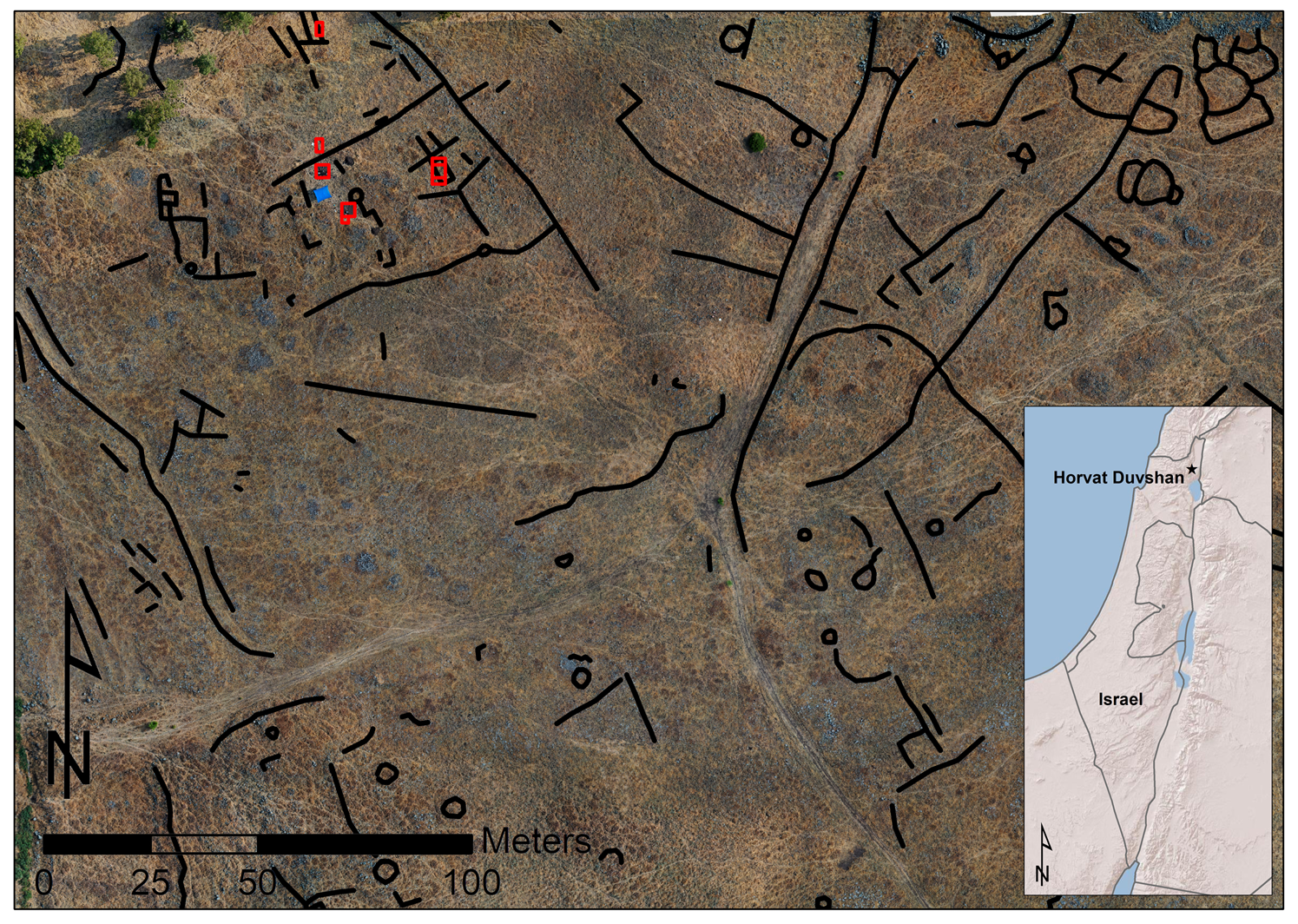
FIGURE 4. (main) orthophotograph of Horvat Duvshan, with visible surface features marked in black and excavation areas shown in red; (inset) locator map for Horvat Duvshan. (Orthophoto by A.C. Hill, courtesy of the Galilee Prehistory Project).
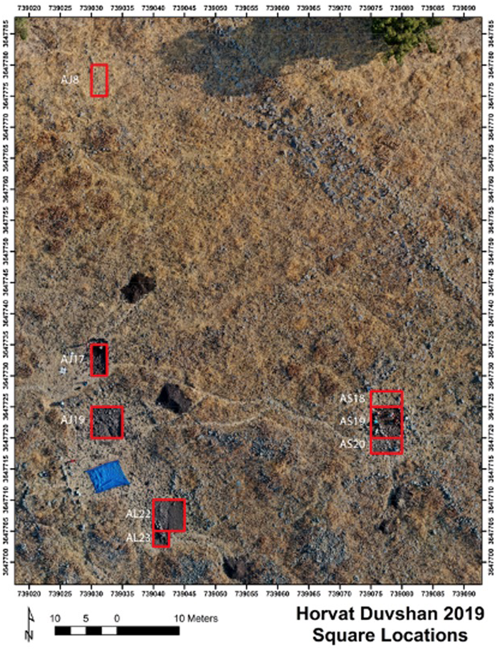
FIGURE 5. Detail of Horvat Duvshan showing 2019 excavation areas. (Orthophoto by A. C. Hill, courtesy of the Galilee Prehistory Project).
The GPP has been using a mostly paperless recording system for several years now, with area supervisors recording notes, sketches, and form data on iPads using FileMaker Pro. We use a combination of a Leica total station and Emlid GNSS hardware for point data collection (Hill et al. Reference Hill2019), including for excavation stakeout, artifact and sample point provenience collection, and GCP collection for handheld, pole, and drone aerial photography. The total station is often a data collection bottleneck for us. We are a relatively small project, usually consisting of no more than 20 people on site at a time, but we still run into problems when the total station might be needed, simultaneously, for recording stratigraphic and artifact data in excavation units in disparate areas of the site, across the wider landscape for GCP recording for drone survey, and for traditional terrestrial survey data collection. We recognized that the project would benefit greatly from a hardware solution that made spatial data more easily accessible to more users on site.
We set up the Marvelmind system around one excavation area at Horvat Duvshan, consisting of three 5 × 5 m grid squares—AS18, AS19, and AS20 (Figure 5). This area contained an apparent Chalcolithic structure, visible on the surface, which we excavated between July 16 and August 7, 2019 (Figure 6). The static beacons were set up in semipermanent locations by driving long rebar stakes into the ground and then bolting short lengths of metal-conduit pipe to the rebar stakes. The fixed beacons could then be mounted in consistent/permanent spots, on the metal conduit, on a daily basis, via custom 3D printed mounts (https://n2t.net/ark:/87296/s69g6b) that held them in the optimum position for recording the excavation area (Figure 7).

FIGURE 6. Beginning of excavations in square AS19, with wall systems on the surface clearly visible. (Photo by A. C. Hill, courtesy of the Galilee Prehistory Project).
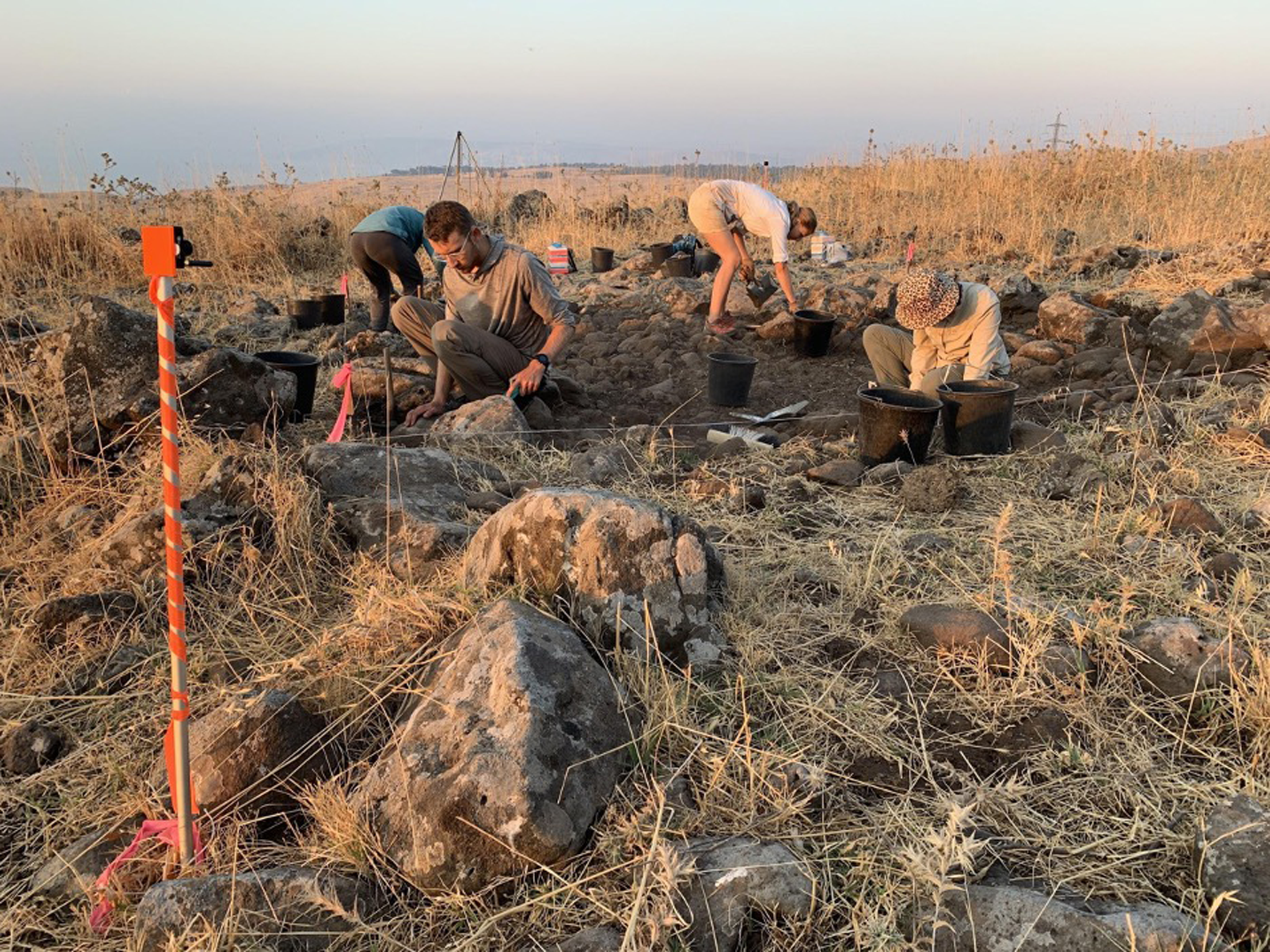
FIGURE 7. A fixed beacon on a 3D printed mount, affixed to a metal conduit. Wrapped in flagging tape, the conduit pipe is more visible, so the beacon is not moved accidentally. (Photo by A. C. Hill, courtesy of the Galilee Prehistory Project).
The entire Marvelmind system is controlled by a central computer connected to a proprietary modem that communicates with all of the static beacons and the hedgehog. This computer is not used to collect data, but just to run the system. For our test, we utilized a custom ruggedized field computer built specifically for this kind of extended fieldwork application (https://n2t.net/ark:/87296/s65p4d). This computer was connected to the Marvelmind modem via a USB cable and was running the Marvelmind system control software (called “Dashboard”). Any Windows- or Linux-based machine could be used for this purpose, but the computer used here was chosen for several reasons. First, this simple, low-powered Windows 10–based computer consists of a Latte Panda single-board computer (the entire computer operates off a small, single, low-powered circuit board) powered from a large rechargeable lithium-ion battery. This combination can run the Marvelmind system for up to 14 hours in the field, without shutting down or recharging. Once set up, the central controller does not need to be monitored, so the case for this computer could be closed and left to run quietly at the margin of the site where it would not be in the way of excavations.
The hedgehog gets its position data via wireless communication with the central controller described above, but it can output its position to a separate device. There are many potential workflows for recording data from the hedgehog, but for our pilot study, we opted for a simple setup using powerful and well-known open-source GIS software. We connected a single hedgehog to an older Surface Pro 2 Windows tablet, which acted as our data collector. We configured the hedgehog to pass NMEA position data to QGIS running on the Surface Pro via a USB cable and using the QGIS “Live GPS Tracking” system (QGIS Development Team 2021), which can be set up to accept the incoming NMEA data stream (Figures 8 and 9). To record data, the hedgehog needed to be tethered to the Windows tablet via a micro USB cable and then placed over the point to be surveyed. This was not ideal, and in a future setup, a wireless interface would be preferable.

FIGURE 8. Photo showing the rugged computer (in back) running the controller software, and the Surface Pro tablet running QGIS with the hedgehog plugged in via USB. (Photo by A. C. Hill, courtesy of the Galilee Prehistory Project).

FIGURE 9. Screenshot of the live “GPS” position (circle with plus sign) from the hedgehog, in QGIS, with a drone-derived orthophoto basemap.
The hedgehog does not store data—it only passes position information in real time to a computer or tablet via USB. The final format of the data will depend on the software or app used to record the data stream. In this case, using QGIS running on a Windows device, we stored and exported the position data as point and polyline shapefiles that could then be brought into ArcGIS as part of our normal post-season mapping process. But it would also be possible, for instance, to output the data in other formats, such as comma delimited .csv files for point data or .kml files that could be brought into Google Earth. This would be easy in the workflow described because the data is being recorded in a full-featured and open-source GIS program, but this might also be possible in many other workflows.
The Marvelmind hedgehogs are not designed as point collection tools for surveying. They are primarily intended for continuous position monitoring for larger devices, such as vehicles, that will have a permanent fixed mount. The case for the hedgehog has a simple, flat bottom, without a standard tripod or survey tripod mount, or an exact survey reference mark for establishing the point of measurement. We experimented with two ways of using the hedgehogs to record coordinates for points of interest and assumed that the measurement reference point for the hedgehog was the center of the base of the case. First, we could take measurements by placing the hedgehog directly over the point to be measured. This was easy and allowed the hedgehog to sit in place while the position was recorded in the tablet. However, this is problematic in many cases if the point to be measured does not have line of sight to the beacons. Alternatively, we mounted the hedgehog on a standard survey pole, using a custom 3D printed mount (https://n2t.net/ark:/87296/s6201f). The spirit level on the survey pole could then be used to ensure that the hedgehog was directly over the point of interest, and we could measure the vertical offset to the base of the hedgehog. Future tests could better investigate errors introduced by these two methods.
Setting up the system had some significant, but anticipated, problems that required many hours of problem-solving and troubleshooting in the field. The primary difficulty was getting the system appropriately georeferenced. When it is first brought online, the system will attempt to measure the distance between each pair of beacons and create a local grid in which to measure the location of the hedgehog. For many uses, this arbitrary local coordinate system would be fine, but for our purposes, we are primarily interested in having the hedgehog provide real-world coordinates that match up to the coordinate system being used on site. Marvelmind provides an option for this. Users can center the grid origin on a beacon and provide georeferencing information for that beacon in WGS84 coordinates in decimal degrees format. The Z height can be manually adjusted to a known benchmark elevation. However, because Marvelmind has a relatively small user base and this use case is at the margin of the current functionality of the system, it was difficult to get the coordinate set permanently to orient the grid to local north and to tune the system so that measured coordinates with the hedgehog would match UTM coordinates recorded with our GNSS equipment. At the time of the pilot test in 2019, this georeferencing was difficult to figure out from the user manual, and there was relatively little in the way of online discussions of this issue. The graphical user interface (GUI) for setting up the system, using the proprietary Marvelmind “Dashboard” software, often seemed counterintuitive or difficult to set up persistently. However, by late 2020—and after several firmware updates—some of these issues seem to be resolved. It is hoped that this will make the system easier to deploy in the future. Alternatively, it might be possible to accept an error in the georeferencing of the system and correct it through postprocessing, although this would be a less elegant solution.
Eventually, we were able to georeference the system and successfully pass 3D coordinate data to QGIS. We then confirmed that the data from the hedgehog lined up with our known coordinates. One instant way of confirming the functionality of the system was by using recently processed orthophotographs of the site as basemaps in QGIS and comparing the position of the hedgehog against the orthophotographs in real time. With the system working correctly, we collected a limited set of polyline data to demonstrate the functionality of the system (Figure 10) before putting the test aside to concentrate on finishing the excavation. This resulted, primarily, in a polyline sketch of the main western wall in square AS19, to the extent that it was visible on the surface at the beginning of excavation.
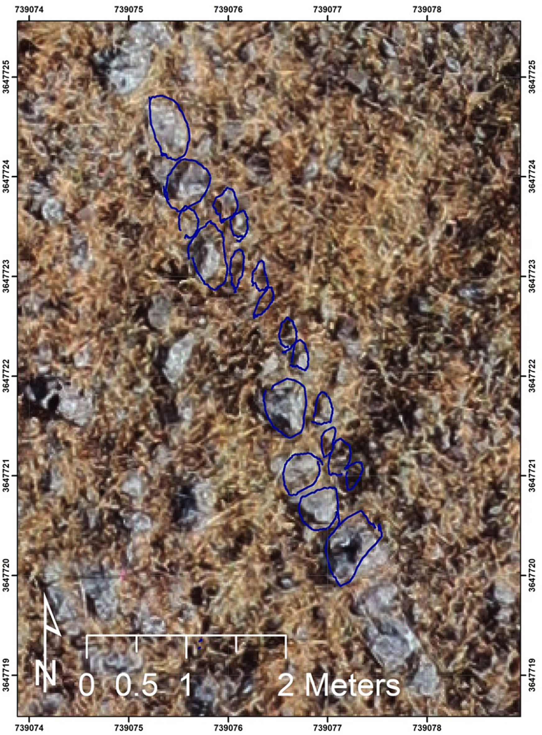
FIGURE 10. Traces of wall stones, using the Marvelmind system, on the western wall of the structure in square AS19 at Horvat Duvshan before excavation.
DISCUSSION
Our pilot project with the Marvelmind system was not intended to replace our normal spatial data collection process. We were not attempting to integrate the system entirely into our fieldwork data process. And we were not, for instance, trying to connect it to our paperless recording system. Instead, we were pilot-testing it in the field to see whether it would work reliably and efficiently under real-world conditions. To that end, we only carried out a limited test of the system to examine how setting it up and collecting data with it might work. In a future deployment, it would be ideal to test the accuracy of the system versus a total station rigorously under a wider range of field conditions. Additionally, we would test a link between the hedgehogs and our paperless recording system so that UTM point coordinates could be passed directly to the site-wide database system for use by individual area supervisors to record point data in their tablets, creating the efficient recording system that an IPS system makes possible.
One of the main features of the Marvelmind system that makes it so appealing for incorporating into data collection is this ability to “pretend” to be a GNSS system by outputting a standard NMEA positioning stream. Many apps, software packages, and even third-party hardware are built to utilize this type of dataflow. Passing this data to QGIS running on a Windows-based tablet is one such option, but there are many other potential workflows on different fieldwork devices (such as iOS or Android tablets, or even traditional data collectors). However, many archaeological projects rely on arbitrary, local coordinate systems that can be difficult to reconcile with the “mock” GNSS data that is being produced by the Marvelmind system in the process described above. For projects where it is already difficult to reconcile GNSS data with local coordinate data, this may not be the best option. It might be possible to configure the system to operate directly in a local grid system, but setting up the link between the hedgehog and the data recording would be more difficult and is beyond the scope of this article.
The availability of always-on, easily accessible, 3D position data gets at an important difference between the value of photogrammetry and the value of hand-drawn site plans (for further discussion of hand drawing, see Morgan and Wright Reference Morgan and Wright2018). In many modern digital excavation workflows, the recording of very high-resolution and accurate photogrammetry models has virtually replaced the collection of analog recording in the form of “hand-drawn” plan and section drawing. Spatially accurate and high-resolution photogrammetry often leads to the assumption that any useful information about 3D relationships can be extracted after the fact during postprocessing and GIS analysis (Roosevelt et al. Reference Roosevelt, Cobb, Moss, Olson and Ünlüsoy2015). However, we should not dismiss the interpretive power of plans and drawings in the field, where researchers are able to highlight the crucial details of structures, strata, and artifacts in situ and in person, and the act of recording individual features can help individuals to understand the archaeology better (Morgan and Wright Reference Morgan and Wright2018). Although many projects are utilizing digital tools, such as tablets, to move analog drawing into a digital workflow, the hardware presented here has the potential to take this a step further by allowing the digitization and extraction of critical features while still recording 3D data at higher levels of accuracy than might be easily accomplished with traditional drawing methods. This greater level of detail recording is possible because of the continual motion tracking of the hedgehogs in real time, making it possible to record complex vector data shapes (for instance, recording data as points, polylines, or polygons). This is not possible with traditional tools such as total stations and GNSS systems, which are primarily designed to collect point data.
CONCLUSION
As tested in 2019, the Marvelmind system was almost—but not quite—ready for deployment in the manner we attempted. The biggest problem was the initial setup of the system. We had difficulty getting the system georeferenced accurately and having that setup persist from day to day. However, some of this was likely user error, given that some of the setup in the controller GUI is not straightforward and was, at the time, not clear either in the user manual or on online forums. Additional problems came from position drift due to wind interference. However, this problem could probably be improved by increasing the resolution setting of the system via a slower update rate and possibly by switching to the ruggedized “outdoor” version of the hardware available from Marvelmind. In terms of the bugs or inconsistency in the firmware, this might be resolved by further testing and time spent with setup, as well as by fixes in the several major firmware updates that have been released since our test. The next major step for attempting to utilize this system with the Galilee Prehistory Project will be a much longer deployment, where reliability across an entire season is assessed. This would allow for a careful assessment of accuracy—tested versus total station data—across all environmental conditions encountered.
Although this “indoor GPS,” or IPS, system is not yet an easily implemented survey-grade tool for archaeological fieldwork, IPS systems have the potential to become an important element in a born-digital fieldwork data-collection system within a variety of fieldwork workflows. IPS systems offer significant benefits for archaeologists working in GPS-denied environments such as cave sites and rockshelters. Such systems can provide always-on access to spatial data and put this data in the hands of people who need access to it constantly: area supervisors, excavators, materials specialists. The update rate and dynamic flexibility of the system means that it could be used as a digitizing tool to record critical features identified by archaeologists in the field. A more functional setup and proper implementation could result in fewer bottlenecks and improved GIS data collection in the field for many projects. Given the current state of the technology, we would encourage archaeologists to begin testing these systems, but they should expect to encounter problems that need context-specific, on-the-fly troubleshooting.
Acknowledgments
We gratefully acknowledge the funding support from the Oriental Institute of the University of Chicago. Thanks go to Uri Berger and David Ilan for logistical and intellectual support. Thanks also to Yosef Stepansky, who shared generously of his time and expertise. Thanks to Madeline Duppenthaler, Wesam Esaid, and Emma McCullough-Stearns for their work with the Eastern Badia Archaeological Project. Special thanks to our intrepid crew for the 2019 excavations at Horvat Duvshan: Lucas Arthur, Jennifer Feng, Blair Heidkamp, Molly Kaplan, Max Price, Julian Thibeau, Ruth Tweedy, and Mollie Wilkinson.
Data Availability Statement
The small shapefile produced as part of the case study described here is available at DOI:10.6084/m9.figshare.14888982.


