1. Introduction
Colloids (here particles  $10\ \textrm {nm}\text {--}10\ {\rm \mu}\textrm {m}$ in characteristic size) can adsorb from immiscible fluid phases bounding an interface (e.g. gas/liquid or non-polar/polar liquid phases) and relocate onto the interface, where they straddle the surface, immersing themselves partly in each phase and forming a monolayer ( figure 1a for a gas/liquid interface; for reviews cf. Binks & Horozov Reference Binks and Horozov2006; Garbin, Crocker & Stebe Reference Garbin, Crocker and Stebe2012a; Deshmukh et al. Reference Deshmukh, van den Ende, Stuart, Mugele and Duits2015; Maestro, Santini & Guzmán Reference Maestro, Santini and Guzmán2018). The adsorption is driven by changes in the fluid interfacial energy and the surface energies of the colloid. Thus when a colloid locates to the bounding surface, it removes part of its surface from contact with one phase, and replaces this contact with contact with the opposite phase. Relocation also removes part of the original fluid interface as the particle is now situated on the surface (Ballard, Law & Bon Reference Ballard, Law and Bon2019). For a spherical colloid of radius
  $a$ relocating, for example, from a non-polar to a polar phase, the change in surface energies on relocation is given by
  $- {\rm \pi}{a^2}\gamma (1 + \cos \theta )^{2}$, where
  $\gamma$ is the tension of the interface,
  $\theta$ is equal to the contact angle as measured through the polar phase and the equilibrium immersion depth
  $d$ is given by
  ${{d}/{a} = 1 + \cos \theta }$, where
  $d$ is measured from the interface to the bottom of the colloid (figure 1a). When the surface of the colloid is partially wetting into the polar phase (
 $\cos \theta \ne -1$), the energy of adsorption can be much greater than the thermal energy, creating the situation that the colloids both straddle the surface and remain irreversibly trapped, forming a relatively permanent colloidal monolayer even if they are active colloidal particles (Fei, Gu & Bishop Reference Fei, Gu and Bishop2017; Yariv Reference Yariv2017). This large energy barrier for particle detachment can be circumvented by large in-plane compressive stresses (see, e.g. Garbin, Crocker & Stebe (Reference Garbin, Crocker and Stebe2012b), Razavi et al. (Reference Razavi, Cao, Lin, Lee, Tu and Kretzschmar2015) and Poulichet & Garbin (Reference Poulichet and Garbin2015)).

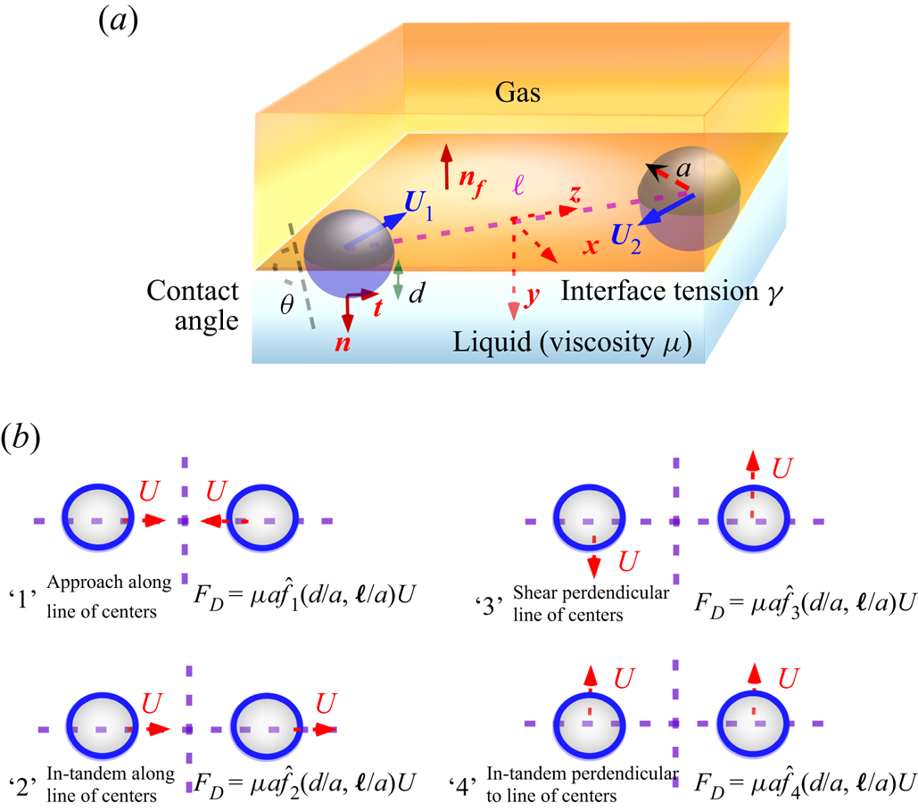
Figure 1. (a) Schematic of the pairwise hydrodynamic interaction between colloids straddling a gas/liquid interface and (b) top view of the fluid interface for the canonical motions in Stokes flow for the pairwise interaction of two particles restricted to motion on the surface.
Colloidal monolayers are the subject of broad technological interest, principally because of their effectiveness in stabilizing foams and emulsion. The trapped particles sterically prevent the interfaces of the bubbles and drops from coalescing, and thereby maintain the stability of the intervening film of the dispersed phase (‘Pickering’ emulsions, Binks Reference Binks2002; Herzig et al. Reference Herzig, White, Schofield, Poon and Clegg2007; Wu & Ma Reference Wu and Ma2016; Huang et al. Reference Huang, Su, Yang, Li, Chen, Li, Zhou, Li and Song2017). Colloidally stabilized dispersions find many applications in food products, consumer products (creams and lotions) and in materials fabrication (solid foams).
Once trapped at the interface, colloids can be subject to external forces exerted in the plane of the surface, e.g. charged (magnetic) particles driven by electric (magnetic) fields, or shear or dilatational flows imposed on the particle-laden interface. These external and hydrodynamic forces cause particle movement in the plane of the surface. Movement can also be driven by interparticle interactions, e.g. repulsive electrostatic (Danov & Kralchevsky Reference Danov and Kralchevsky2006; Oettel & Dietrich Reference Oettel and Dietrich2008) or magnetic (Vandewalle et al. Reference Vandewalle, Clermont, Terwagne, Dorbolo, Mersch and Lumay2012) forces for charged or magnetic particles, respectively, or attractive van der Waals forces (Bresme & Oettel Reference Bresme and Oettel2007). Attached particles are also subject to attractive (‘capillary’) interparticle forces, derived from overlapping local curvature changes between the particles induced by the anisotropy in particle shape, surface roughness of the contact line along the particle surface or, for larger and heavier colloids, surface depressions due to the particle weight (Kralchevsky & Nagayama Reference Kralchevsky and Nagayama2000; Stamou, Duschl & Johannsmann Reference Stamou, Duschl and Johannsmann2000; Danov & Kralchevsky Reference Danov and Kralchevsky2010). The motion generated by these external forces, flows and interparticle interactions is resisted by viscous tractions exerted on the colloids by the fluids in the adjoining phases. Thus, in addition to their importance in dispersion technology, colloidal monolayers at a fluid interface serve as a model for studying particle dynamics and hydrodynamic interaction in two dimensions under a broad array of external forces and self-interactions. As such, the model can be used to gain insight into many phenomena associated with two-dimensional (2-D) particle dynamics, including self-organization, microstructure formation (chains and patterns), crystallization, phase transitions and surface rheology, and how these phenomena are tuned by the forces, interactions and hydrodynamics. This insight can guide the design of new particle-constructed materials using a bottom-up approach. (Park & Lee Reference Park and Lee2014; Booth & Dryfe Reference Booth and Dryfe2015).
In this study, attention is focused on the hydrodynamic interactions of a pair of spherical colloids as they translate along the surface of a flat 2-D fluid landscape separating gas from a liquid phase (figure 1a). Several investigations have examined, both experimentally and theoretically, hydrodynamic interaction in conjunction with understanding 2-D particle dynamics, and we briefly review these. The most relevant for this study are examinations of the pairwise interaction of two spherical colloids attached to a planar fluid interface, and driven together by capillary attraction (Vassileva et al. Reference Vassileva, van den Ende, Mugele and Mellema2005; Boneva et al. Reference Boneva, Christov, Danov and Kralchevsky2007, Reference Boneva, Danov, Christov and Kralchevsky2009; Dalbe et al. Reference Dalbe, Cosic, Berhanu and Kudrolli2011; Dani et al. Reference Dani, Keiser, Yeganeh and Maldarelli2015). These studies measured the separation distance as a function of time ( $\ell (t)$, figure 1a). They also modeled the motion by assuming Stokes flow, as the Reynolds numbers are typically small due to the small size of the colloids and the fact that flows driven by capillary attraction (or any of the interparticle interactions) are small. They also assumed the interface is undeformed by the flow and remains flat, as the viscous forces in the generated flows are small relative to surface tension forces (small capillary number, Ca) and the particle penetration depth does not change. Here, for the gas/liquid interface (figure 1a), the capillary number is defined as
  $Ca=\mu U/\gamma$, where
  $\gamma$ is the tension of the gas/liquid interface,
  $\mu$ is the Newtonian viscosity of the liquid phase bounding the interface and
  $U$ is the characteristic colloid velocity. In addition, the rotation of the colloids due to the translation is neglected, under the assumption that the contact line pins the motion due to surface roughness (Dörr & Hardt Reference Dörr and Hardt2015; Dörr et al. Reference Dörr, Hardt, Masoud and Stone2016).
With the above assumptions, the hydrodynamic motion of a pair of particles can be decomposed, due to the linearity of the Stokes equations and the fact that the interface is assumed flat and undeformed by the flow, into four canonical motions as shown in figure 1(b) for a gas/liquid interface. Two motions are modes in which the colloids move along the line of centres, either ‘1’ approaching or moving away from each other with velocity  $U$ or ‘2’ moving in-tandem with velocity
  $U$. Two are modes in which the colloids move perpendicular to the line of centres, either ‘3’ a shear motion in which the particles move in equal and opposite directions with velocity
  $U$ or ‘4’ an in-tandem motion. With each mode there is a drag exerted on the particle in the flow direction which can be formulated in terms of non-dimensional drag coefficients (non-dimensionalized by
  $\mu aU$). These drag coefficients are a function of the immersion depth (
 $d/a$) and separation distance
  $\ell /a$. Thus for the modes along the line of centres, the dimensional drag on the particles along the centre-to-centre axis are given by
  ${\hat f_i}(d/a,\ell /a )\mu aU$ (i=1, 2), where
  ${\hat f_i}(d/a,\ell /a)$ is the drag coefficient (non-dimensionalized by
  $\mu aU$). For the modes involving motion perpendicular to the line of centres, the dimensional drag is
  ${\hat f_i}(d/a,\ell )\mu aU$ (
 $i=3, 4$), and
  ${\hat f_i}(d/a,\ell )$ are the non-dimensional drag coefficients (figure 1b). (Note, for interfaces bounded by two liquids, all these coefficients are also a function of the the viscosity ratio of the fluids; in this case the coefficients are non-dimensionalized by one of the two viscosities.) These drag coefficients have not been computed, although the coefficient for an isolated particle translating along a flat surface (
 $k (d/a)$, non-dimensionalized by
  $\mu aU$) has been obtained as a function of immersion depth and the viscosity ratio using either eigenfunction expansion (O'Neill, Ranger & Brenner Reference O'Neill, Ranger and Brenner1985), finite element (Danov et al. Reference Danov, Aust, Durst and Lange1995; Danov, Dimova & Pouligny Reference Danov, Dimova and Pouligny2000), boundary integral (Fischer, Dhar & Heinig Reference Fischer, Dhar and Heinig2006; Pozrikidis Reference Pozrikidis2007) or integral transform methods (Dani et al. Reference Dani, Keiser, Yeganeh and Maldarelli2015; Dörr et al. Reference Dörr, Hardt, Masoud and Stone2016). In the pairwise interaction studies, since the colloids straddling the interface are driven by capillary attraction, which is centrosymmetric, the separation distance is given by a balance of the capillary interaction force
  $F_{cap, \parallel }$ and the drag for mutual approach
  ${{F_{cap,\parallel }} = \mu a{{\hat f}_1}(d/a,\ell /a){{}}}$. In Vassileva et al. (Reference Vassileva, van den Ende, Mugele and Mellema2005), Dalbe et al. (Reference Dalbe, Cosic, Berhanu and Kudrolli2011), Boneva et al. (Reference Boneva, Christov, Danov and Kralchevsky2007, Reference Boneva, Danov, Christov and Kralchevsky2009) and Dani et al. (Reference Dani, Keiser, Yeganeh and Maldarelli2015), for
  ${{\hat f}_1}(d/a,\ell /a)$ the following approximation is used:
 \begin{equation} \frac{{{{\hat f}_1}(d/a,\ell /a)}}{{k(d/a)}} \approx\, \frac{\hat f_{1,\infty}(\ell /a)}{6{\rm \pi}} , \end{equation}
where  ${{\hat f_{1,\infty }(\ell /a)}/{6{\rm \pi} }}$ is the drag coefficient for the pairwise approach of two particles completely immersed in a liquid divided by the Stokes drag coefficient of an isolated particle completely immersed in the liquid (both coefficients non-dimensionalized by
  $\mu aU$). The pairwise interaction drag coefficients in an infinite medium for mutual approach and the other three modes have all been computed (for a summary, see Jeffrey & Onishi (Reference Jeffrey and Onishi1984) and Appendix A, § A.2). Note that for the gas/liquid interface, (1.1) is exact (for all four modes) for the case of an immersion depth
  $d/a=1$ and either a gas/liquid interface or equal viscosities for the bounding phases. This follows from the fact that for these cases, the shear stress on the fluid surface is zero, and this makes the flow field underneath the interface exactly the same as the flow field around a sphere in an infinite medium. For this reason, the isolated drag coefficient for a sphere straddling a gas/liquid interface is 1/2 the drag on a sphere in an infinite medium, or
  $3{\rm \pi}$, and the drag coefficients
  ${{\hat f}_i}(d/a,\ell /a)$ are equal to 1/2 the coefficients in an infinite medium,
  $\hat {f}_{i,\infty }(\ell /a)$, as also follows from (1.1). (For equal viscosities and
  $d/a=1$,
  $k(d/a=1)=6{\rm \pi}$ and
  ${{\hat f}_i}(d/a,\ell /a)=\hat {f}_{i,\infty }(\ell /a)$, in agreement with (1.1).) In Vassileva et al. (Reference Vassileva, van den Ende, Mugele and Mellema2005), Dalbe et al. (Reference Dalbe, Cosic, Berhanu and Kudrolli2011), Boneva et al. (Reference Boneva, Christov, Danov and Kralchevsky2007, Reference Boneva, Danov, Christov and Kralchevsky2009) and Dani et al. (Reference Dani, Keiser, Yeganeh and Maldarelli2015), the measured separation distance with time agreed with the theoretical prediction using (1.1), although the theory was tested for liquid–liquid systems in which the viscosities were equal or not very disparate and hence the colloids interacted as if they were in a infinite medium, or the immersion depth was close to
  $d/a=1$ for a system with disparate viscosities acting as a gas/liquid interface.
Many experimental and theoretical studies have investigated hydrodynamic interactions among multiple colloidal particles straddling a fluid interface. For external flows applied to the interface, examples are: Laal Dehghani, Khare & Christopher (Reference Laal Dehghani, Khare and Christopher2017) and Barman & Christopher (Reference Barman and Christopher2016); they studied a surface shear (Couette) flow, undertaking a 2-D Stokesian dynamics simulation which included the interparticle forces of capillary and electrostatic repulsion, and later extended this work to study aggregation in the absence of an imposed flow (Laal-Dehghani & Christopher Reference Laal-Dehghani and Christopher2019; Rahman, Laal-Dehghani & Christopher Reference Rahman, Laal-Dehghani and Christopher2019b; Rahman et al. Reference Rahman, Laal-Dehghani, Barman and Christopher2019a). In these studies, pairwise hydrodynamic interactions are accounted for by (1.1). For shear flow imposed across the interface, Vidal & Botto (Reference Vidal and Botto2017) examined theoretically the Stokes drag on a planar array of immobile colloids straddling a gas/liquid interface ( $d/a=1$) by placing the array, fully immersed, at the midplane of a channel with a shear flow and using the symmetry of the configuration to find the drag on the particles at the gas/liquid interface as 1/2 the fully immersed drag. De Corato & Garbin (Reference De Corato and Garbin2018) and Huerre, De Corato & Garbin (Reference Huerre, De Corato and Garbin2018) examined microstructure development for particles attached to a planar or spherical gas/liquid interface under rapid surface expansion, and the related capillary attraction between these particles under normal rapid periodic forcing in the inviscid rather than the Stokes limit.
Several studies have examined the 2-D self-organization of colloids attached to a fluid interface as driven by interparticle interaction forces. Mesoscopic discrete element and Brownian dynamics simulations equate the Stokes drag force on the particles to the interparticle interactions and a stochastic Brownian force, see Nishikawa et al. (Reference Nishikawa, Maenosono, Yamaguchi and Okubo2003), Fujita et al. (Reference Fujita, Nishikawa, Okubo and Yamaguchi2004), Nishikawa et al. (Reference Nishikawa, Fujita, Maenosono, Yamaguchi and Okudo2006), Millett & Wang (Reference Millett and Wang2011), and Uzi, Ostrovski & Levy (Reference Uzi, Ostrovski and Levy2016). These studies, for colloids attached to planar fluid surfaces, focus on simulating the self-organization, with detailed modelling (including the use of diffuse interface theory) of the capillary attraction and electrostatic interaction forces, and of the frictional forces with a solid surface beneath the interface if the fluid interface overlays a substrate. But the effect of hydrodynamic interactions between the particles as in figure 1(b), are not addressed, as the fluid drag forces on the particles are formulated using the Stokes drag force on a single, isolated particle,  $k\mu a U$, independent of the immersion depth.
A model 2-D particle system for understanding interparticle interactions which has attracted considerable attention consists of particles which are magnetized by an external magnetic field. These particles are either attached to a gas/aqueous interface (e.g. Vandewalle et al. Reference Vandewalle, Clermont, Terwagne, Dorbolo, Mersch and Lumay2012; Lumay et al. Reference Lumay, Obara, Weyer and Vandewalle2013; Vandewalle, Obara & Lumay Reference Vandewalle, Obara and Lumay2013; Darras et al. Reference Darras, Mignolet, Vandewalle and Lumay2018) or are completely wetted by an aqueous phase and lie in a liquid layer immediately above an inverted planar meniscus (Zahn, Méndez-Alcaraz & Maret Reference Zahn, Méndez-Alcaraz and Maret1997; Rinn et al. Reference Rinn, Zahn, Maass and Maret1999; Zahn & Maret Reference Zahn and Maret1999; Kollmann et al. Reference Kollmann, Hund, Rinn, Nägele, Zahn, König, Maret, Klein and Dhont2002; Löwen et al. Reference Löwen, Messina, Hoffmann, Likos, Eisenmann, Keim, Gasser, Maret, Goldberg and Palberg2005) or between two plates (Du, Hilou & Biswal Reference Du, Hilou and Biswal2018; Hilou et al. Reference Hilou, Du, Kuei and Biswal2018). When the field is applied normal to the interface, the resultant magnetic dipoles repel each other, while when the field is applied with a horizontal component, the magnetized particles can move in the surface plane. Brownian dynamics simulations have been undertaken to model the experiments in which the particles are completely submerged and translate next to the inverted fluid interface and repel each other due to a normal magnetic field (Zahn et al. Reference Zahn, Méndez-Alcaraz and Maret1997; Rinn et al. Reference Rinn, Zahn, Maass and Maret1999; Kollmann et al. Reference Kollmann, Hund, Rinn, Nägele, Zahn, König, Maret, Klein and Dhont2002). These simulations incorporate pairwise hydrodynamic interactions in an infinite medium using the Rotne–Prager approach formulation, and demonstrate by comparison with experiments that the self-diffusivity is enhanced by the presence of hydrodynamic interactions for the repulsive  $r^{-3}$ interparticle potential corresponding to the magnetic dipolar repulsion. The importance of incorporating hydrodynamic interactions in the dynamics of a colloid monolayer confined to the midplane between two parallel walls is detailed in the Stokesian dynamics studies of Pesché & Nägele (Reference Pesché and Nägele2000a,Reference Pesché and Nägeleb) using different interparticle potentials. Pairwise hydrodynamic interaction was accounted for using the drag coefficients for an infinite medium augmented to include the interaction with the wall. Although in these later studies the particles are completely immersed and not attached to the interface (and surface specific forces like capillary attraction were not examined), they can be considered models for surface confined colloids for the case in which
  $d/a=1$ and the colloids are attached to a gas/liquid interface or an interface bounding phases of equal viscosity. Similarly, Bleibel et al. (Reference Bleibel, Domínguez, Günther, Harting and Oettel2014) highlighted the importance of hydrodynamic interaction in the motion of colloid particles restricted to a plane in a liquid by demonstrating that the hydrodynamic interaction can give rise to anomalous fast diffusion. Lattice–Boltzmann methods have also been applied to model the self-organization of magnetized colloids attached to an interface – e.g. Xie, Davies & Harting (Reference Xie, Davies and Harting2016, Reference Xie, Davies and Harting2017) examined, on planar and spherical fluid interfaces, the interaction of magnetic ellipsoidal and Janus particles that are tilted (relative to the surface tangent) by an external magnetic field to create surface deformation and capillary attraction. Although the Lattice–Boltzmann method implicitly incorporates hydrodynamic interactions between the particles, these effects are not specifically studied.
The above summary highlights the importance of accounting for hydrodynamic interactions in describing the 2-D dynamics of colloids attached to a fluid interface. The summary also notes that the inclusion of pairwise interaction has only approximately been accounted for by using either the approximation (1.1), or by assuming  $d/a=1$ and the interface to be a gas/liquid surface or a liquid/liquid interface with equal bulk phase viscosities (in which case (1.1) is exact). The purpose of this study is to provide a more exact treatment of pairwise interaction by numerically solving for the drag coefficients for the four canonical motions of figure 1(b) as a function of the immersion depth, and to assess the validity of (1.1) for all modes. In this way, we particularly aim to understand the correct dependence of the drag coefficients on the immersion depth.
2. Formulation
We consider the general motion in quasi-steady Stokes flow of a pair of colloids of identical radius  $a$ moving arbitrarily with velocities
  $\boldsymbol {U}_{1}$ and
  $\boldsymbol {U}_{2}$ along a fluid interface (figure 1a) between a gas and an incompressible Newtonian liquid phase (viscosity
  $\mu$). We solve only for the translational motion of the colloids along the interface (contact line pinning is assumed to prevent rotation). The fluid interface is assumed to be stress-free and remain flat up to the contact lines on the particle surfaces, even as the particles move (small capillary number), and the immersion depth
  $d$ of the particle into the liquid, as defined by its contact angle, is identical for both particles and remains constant as the colloids translate along the surface. The mass conservation (incompressibility constraint) and the Stokes field equations for flow in the underlying fluid are:
 \begin{gather} \boldsymbol{\nabla} \boldsymbol{\cdot} {\boldsymbol{v}} = 0 \end{gather}
 \begin{gather}- \boldsymbol{\nabla} p + \nabla^{2} {\boldsymbol{v}}= 0, \end{gather}
where  $\nabla ^2$ is the Laplacian (non-dimensionalized by the particle radius
  $a$),
$a$),  $\boldsymbol {v}$ is the local fluid velocity field non-dimensionalized by
  $U$ which scales the magnitude of the velocities
  $\boldsymbol {U}_{1}$ and
  $\boldsymbol {U}_{2}$, and
  $p$ is the pressure normalized by
  ${{{\mu U}}/{a}}$, where
  $\mu$ is the viscosity of the liquid.
The velocity normal to the fluid surface is zero and the tangential shear stress is zero,  $({\boldsymbol {I}} - {\boldsymbol {n}}_{f} {\boldsymbol {n}}_{f}) \boldsymbol {\cdot } \{ {\boldsymbol {\nabla } {\boldsymbol {v}} + {{(\boldsymbol {\nabla } {\boldsymbol {v}})}^{\dagger} }} \} \boldsymbol {\cdot } {\boldsymbol {n}} _{f}= {\boldsymbol {0}}$ where
  ${\boldsymbol {n}}_{f}$ is the normal vector to the upper gas/liquid interface, and the gradients in the fluid velocity are evaluated at the fluid interface. This stress free condition is formulated for the two orthogonal tangential directions normal to the fluid surface. At the surface of the particles, the normal component of the fluid velocity at the surface,
  $\boldsymbol {v}_s \boldsymbol {\cdot } \boldsymbol {n}$, where
  $\boldsymbol {n}$ is a unit normal (figure 1a) is equal to the normal component of the particle velocity at the surface (
 $(\boldsymbol {U}_{i}/U) \boldsymbol {\cdot } \boldsymbol {n} = \boldsymbol {v}_s \boldsymbol {\cdot } \boldsymbol {n}$).
The hydrodynamic motion that we are studying in this manuscript assumes that the contact line is pinned (due, for example, to surface roughness), and therefore the particles only translate but do not rotate along the planar surface. Pinning of the contact line indicates no relative motion between the solid and the surface, a no-slip condition. In general, slip at the interface is formulated through a Navier slip condition with slip coefficient  $\lambda$:
 \begin{equation} \boldsymbol{t} \boldsymbol{\cdot} (\boldsymbol{U}_{i}/U - \boldsymbol{v}_{s}) = \frac{\lambda}{a} \boldsymbol{n} \boldsymbol{\cdot} (\boldsymbol{\nabla} \boldsymbol{v}+\boldsymbol{\nabla} \boldsymbol{v}^{{{\dagger}}})_{s} \boldsymbol{\cdot} \boldsymbol{t}, \end{equation}
where  $\boldsymbol {t}$ is a unit tangent vector to the colloid surface (figure 1a), and
  $\lambda =0$ corresponds to no-slip. In our study, instead of assuming a zero slip coefficient, we use a small finite value
  $\lambda /a=0.01$. Our reason is related to our finite element technique utilized to obtain numerical solutions (implemented with the COMSOL Multiphysics numerical software package). For
  $\lambda /a=0.01$, velocity gradients near the surface are reduced relative to the no-slip case, and a less dense meshing is required near the surface to obtain converged solutions for the translational drag coefficient. The finite element solution requires the inversion of the matrix of constants that approximate the variables in the elements of the mesh; the smaller the mesh, the smaller the matrix and the fewer iterations are required to obtain an accurate inversion. The fewer the iterations, the smaller the computation time. Some test solutions were undertaken with a zero slip condition for
  $d/a=1$, and these simulations required denser meshing and resulted in longer computational times for obtaining solutions for the translational drag coefficients. Converged values for the drag coefficient assuming a no-slip coefficient were within one or two per cent of the values obtained for
  $\lambda /a=0.01$. This in fact is consistent with O'Neill et al. (Reference O'Neill, Ranger and Brenner1985), who obtained analytical calculations for the drag coefficient of a colloid straddling a gas/liquid interface for a single particle symmetrically located at the interface. They showed that the translational coefficient for a single particle for this case is
  ${ 3} {\rm \pi}(({1 + 2\lambda /a})/({1 + 3\lambda /a})) \approx {3} {\rm \pi}( 1-\lambda /a)$, and hence the no slip-coefficient is within one per cent of the value for the drag coefficient for no-slip conditions.
The hydrodynamic flow generates a traction on the surface of the translating particle, and for each flow realization (figure 1b) these are given (in non-dimensional form) by:
 \begin{equation} {\boldsymbol{F}}_{P} = \mathop{{\int\!\!\!\!\!\int}\mkern-21mu {\bigcirc}}_{\varGamma _P} \left( {\boldsymbol{\sigma} \boldsymbol{\cdot} {\boldsymbol{n}}} \right) \textrm{d}s, \end{equation}
where  $\varGamma _P$ denotes the portion of the particle surface in contact with the liquid, and
  $\boldsymbol {\sigma } =-p\boldsymbol {I} + \boldsymbol {\nabla } \boldsymbol {v}+\boldsymbol {\nabla } \boldsymbol {v}^{{\dagger} }$ is the total stress tensor. From the computed traction, the drag coefficients are computed as described further on. The hydrodynamic equations and boundary conditions were solved using the COMSOL Multiphysics numerical software, which uses the finite element method to solve the field equations and boundary conditions as described in Appendix A. Appendix A also provides details of the validation of the calculations.
3. Results
In the following, we treat separately the hydrodynamics and calculated drag coefficients for the two modes along the line of centres (§ 3.1) and the two modes perpendicular to the line of centres (§ 3.2).
3.1. Motion along line of centres
Figure 2(a) shows a schematic of the two particles approaching each other along their line of centres ( $z$ axis), one translating along the interface with velocity
  $U$ in the positive
  $z$ direction and the other moving in negative
  $z$ direction with velocity
  $-U$ in the laboratory frame (canonical motion ‘1’, figure 1b). Assuming that the liquid underlying the interface is an aqueous phase, figure 3 demonstrates the magnitude of the flow field around the two particles, either hydrophilic (
 $\theta ={\rm \pi} /3, d/a=1.5$), neutral (
 $\theta ={\rm \pi} /2, d/a=1$) or hydrophobic (
 $\theta =2{\rm \pi} /3, d/a=0.5$), assuming the liquid is water. The plane shown is the symmetry plane for the
  $z$ motion, i.e.
  $x=0$, with
  ${{v}_{x}=0}$. The colour scheme for the flow field in the figure provides the magnitude of the velocity in the
  $x=0$ plane scaled by the colloid velocity
  ${U}$, i.e
  ${{[ {{{v}}_z^2 + {{v}}_y^2} ]^{1/2}}/U}$. The flow field also shows vectors of the velocity in this plane scaled by the velocities of the colloids,
  $U$. As would be expected, the more hydrophilic the particle is, the greater its penetration in the liquid phase and the larger is the hydrodynamic disturbance under the free interface. For the hydrophilic
  $d/a=1.5$ and neutrally wetting (
 $d/a=1.0$) immersion depths, the flow between the colloids is a squeezing lubrication flow, with high velocity developing between the colloids. The colloids can in principle touch (as their equators are on or below the interface), although lubricating hydrodynamic stresses (see below) will prevent the contact. The maximum velocity in the region between the colloids occurs slightly below their equator (and down from the free surface), and interestingly, the magnitude of the velocity is low just underneath the interface. The plane perpendicular to the interface and equidistant between the two spheres (
 $z=0$) is a plane of reflectional symmetry (a separatrix), with the velocity in the
  $z$ direction equal to zero and the
  $y$ velocity as in figure 2(c), which accounts for the removal of the fluid between the colloids. Since the velocity at the free interface in the
  $x$ direction is required to be zero (the interface remains flat), a maximum in the
  $y$ velocity develops downward, away from the interface. This maximum is largest for the hydrophilic colloid, and is larger than the velocity of the particles (
 ${\approx }1.2U$). In the case of the hydrophobic particle, with less immersion into the liquid (
 $d/a=0.5$), large velocities along the reflectional symmetry plane are not developed because there is no strong squeezing of the intervening liquid as the particles contact each other above the free surface. For this case, the maximum in the
  $y$ velocity is only half of the particle velocities. It is worth noting that while the forces on two touching neutrally wetting and hydrophilic particles are singular, they remain finite for hydrophobic spheres since the particles do not contact in the liquid phase.

Figure 2. Motion along the line of centres for two particles, one translating in the negative  $z$ direction and with velocity
  $-U$ and the other in the positive
  $z$ direction and with velocity
  $U$ on the surface of a semi-infinite liquid in the laboratory frame, (b) normalized drag coefficient, (v) velocity in the
  $y$ direction and (d) pressure in the plane
  $x=0$ and along the mid-line as a function of
  $y$, as function of interparticle separation for hydrophilic (
 $\theta ={\rm \pi} /3$,
  $d/a=1.5$), neutral (
 $\theta ={\rm \pi} /2$,
  $d/a=1$) and hydrophobic (
 $\theta =2{\rm \pi} /3$,
  $d/a=0.5$) particles, assuming the liquid to be water.

Figure 3. Streamlines and velocity maps for the motion in the  $x=0$ symmetry plane, for particles approaching along their line of centres for hydrophilic,
  $\theta ={\rm \pi} /3$,
  $d/a=1.5$, neutral,
  $\theta ={\rm \pi} /2$,
  $d/a=1$ and hydrophobic
  $\theta =2{\rm \pi} /3$,
  $d/a=0.5$ particles, assuming the liquid to be water for mutual approach along the line of centres.
The (non-dimensional) hydrodynamic drag force (i.e. the drag coefficient) in the  $z$ direction exerted on each of the particles by their mutual approach along their line of centres is denoted by
  $\hat {f}_{1}(\ell /a,d/a)$, where
  $\ell$ is the separation distance and is calculated from (2.4) for the approach realization, i.e.
  ${F}_{P,z}(\ell /a, d/a)=\hat {f}_{1}$. Plotted in figure 2(b) for three values of the immersion depth, is
  ${f}_{1}(\ell /a,d/a)= \hat {f}_{1}(\ell /a,d/a)/ k(d/a)$, which is the non-dimensional drag coefficient normalized by the (non-dimensional) drag coefficient exerted on each of these particles when the separation distance
  $\ell /a$ is very large (the single particle drag coefficient,
  ${F}_{P,z}(\ell /a \to \infty ,d/a)=k(d/a)$). The calculation of
  $k(d/a)$ is undertaken separately by locating only a single particle on the surface in the computational domain. The single particle drag results are summarized in table 2 in Appendix A for the immersion depths
  $d/a = 1.5$, 1 and 0.5. The single particle coefficients as given in table 2 show the expected result that as the immersion depth increases, the drag coefficient increases and that, owing to symmetry, the coefficient for the neutrally wetting case is one-half the Stokes drag coefficient for a particle moving in an infinite medium,
  $k(d/a=1)=3 {\rm \pi}$. In interpreting figure 2(b), we note first that for the neutrally wetting particle, due to symmetry, the drag coefficient should be equal to 1/2 the coefficient for two particles approaching along their line of centres in an infinite medium (
 $\,\hat {f}_{1,\infty }(\ell /a)$). Calculations of
  $\hat f_{1,\infty }(\ell /a)$ have been undertaken, see Jeffrey & Onishi (Reference Jeffrey and Onishi1984) and Boneva et al. (Reference Boneva, Christov, Danov and Kralchevsky2007), and their results are given in Appendix A (§ A.2) as this coefficient normalized by an isolated particle translating in an infinite medium,
  $\hat f_{1,\infty }(\ell /a)/6 {\rm \pi}$. In figure 2(b),
  $\hat {f}_{1,\infty }(\ell /a)/6 {\rm \pi}$ is plotted from Boneva et al. (Reference Boneva, Christov, Danov and Kralchevsky2007), and it is shown to agree with
  $f_{1}(\ell /a,d/a=1)$, providing further verification of the COMSOL calculations.
Figure 2(b) demonstrates that for colloids which are neutrally wetting or hydrophilic, a large drag coefficient develops as the colloids come in close contact ( $\ell /a \to 2$). As in any lubrication flow caused by the approach of two surfaces to each other, the large drag is caused by the increased viscous resistance to removing the liquid in between the particles. This resistance causes a large pressure to be developed between the colloids, as is clear in figure 2(d), and the resulting large velocities in the gap are shown in figure 2(c). As the particles approach touching, this resistance becomes infinite. However, for the non-wetting colloid, which rides with its equator above the interface, the mutual approach to contact is not accompanied by a complete removal of the fluid from between the particles. (The particles in fact can contact above the interface.) As a result, the pressures required to remove the liquid and velocity are much lower, and the drag coefficient asymptotes to a constant value as
  $\ell /a \to 2$. As a consequence of this very different behaviour between the non-wetting and wetting spheres, the useful approximation for the non-dimensional drag,
  $f_{1}(\ell /a,d/a)=\hat {f}_{1}(\ell /a,d/a)/k(d/a) \approx \,\hat f_{1,\infty }(\ell /a)/6 {\rm \pi}$, (1.1), while exact for neutrally wetting, is only approximate for
  $d=0.5$ and
  $d=1.5$. (Compare the Danov & Kralchevsky (Reference Danov and Kralchevsky2010) expression for
  $\hat {f}_{1,\infty }(\ell /a)/6 {\rm \pi}$ in figure 2(b) with the simulations for the wetting and non-wetting drag coefficients.)
Figure 4(a) shows a schematic of the two particles moving in tandem along their line of centres ( $z$ axis), both translating along the interface with velocity
  $U$ in the positive
  $z$ direction in the laboratory frame – canonical motion ‘2’ in figure 1(b). As in figure 2, assuming that the liquid underlying the interface is an aqueous phase, figure 5 demonstrates the magnitude of the flow field around two hydrophilic (
 $\theta ={\rm \pi} /3, d/a=1.5$), neutral (
 $\theta ={\rm \pi} /2, d/a=1$) and hydrophobic (
 $\theta =2{\rm \pi} /3, d/a=0.5$) particles, again assuming the liquid is water. Some of the features are the same as in figure 2. The more hydrophilic the particle is, the greater its penetration in the liquid phase and the larger the hydrodynamic disturbance under the free interface. Note, however, that unlike figure 2, the liquid between the particles is not squeezed out, but entrained and moves at a uniform velocity equal to the tandem velocities of the particles. This uniform motion of a trapped region of fluid is also clear in figure 4(c), which plots the velocity in the
  $z$ direction along the
  $y$ axis at the midplane between the particles (
 $z=0$) and perpendicular to the interface. Along this plane, for
  $y$ depths below the surface and below the particles, the
  $z$ velocity rapidly drops to zero. The pressure along the midplane is plotted in figure 4(d), and demonstrates that the pressures in the intervening fluid between the colloids are much smaller, by an order of magnitude, when compared to the the squeezing flow of figure 2. This is not surprising as the lubrication flow created when the particles approach acts to drive fluid from between the particles through the narrow gap. In addition, all pressures along the
  $y$ axis at the midplane drop to zero at the value of
  $y$ corresponding to the bottom of the colloid.

Figure 4. (a) Schematic of motion along the line of centres for two particles, both translating in the positive  $z$ direction and with velocity
  $U$ on the surface of a semi-infinite liquid in the laboratory frame, (b) normalized drag coefficient as function of interparticle separation, (c) velocity in the
  $z$ direction and (d) pressure both in the plane
  $x=0$ and along the mid-line as a function of
  $y$ for hydrophilic (
 $\theta ={\rm \pi} /3, d/a=1.5$), neutral (
 $\theta ={\rm \pi} /2, d/a=1$) and hydrophobic (
 $\theta =2{\rm \pi} /3, d/a=0.5$), particles assuming the liquid to be water.

Figure 5. Streamlines and velocity maps for the motion in the  $x=0$ symmetry plane for hydrophilic (
 $\theta ={\rm \pi} /3, d/a=1.5$), neutral (
 $\theta ={\rm \pi} /2, d/a=1$) and hydrophobic (
 $\theta =2{\rm \pi} /3, d/a=0.5$) particles assuming the liquid to be water for tandem motion along the line of centres.
The normalized drag coefficient  ${f}_{2}(\ell /a,d/a)$ for the drag exerted on each of the particles for their in-tandem motions,
  ${f}_{2}(\ell /a,d/a)= \hat {f}_{2}(\ell /a,d/a)/ k(d/a)$, is plotted as a function of
  $\ell /a$ in figure 4(b). Here
  $\hat {f}_{2}(\ell /a,d/a)$ is the non-dimensionalized coefficient for the in-tandem realization ((2.4), i.e.
  ${F}_{P,z}(\ell /a, d/a)=\hat {f}_{2}$). Note that the normalized coefficients for each of the immersion depths collapse to a single curve, which is coincident with the curve from the expression of Jeffrey & Onishi (Reference Jeffrey and Onishi1984) for the normalized drag exerted on spheres moving in a bulk medium with in-tandem motion,
  ${\hat {f}}_{2,\infty }/6{\rm \pi}$, as detailed in Appendix A. Thus the approximation for the in-tandem non-dimensional drag coefficient,
  ${\hat {f}_2}(\ell /a,d/a)/k(d/a) = {{\hat {f}}_{2,\infty }}(\ell /a)/6{\rm \pi}$, while exact for neutrally wetting because of symmetry, is also an excellent approximation for the other values of
  $d/a$.
3.2. Motion perpendicular to the line of centres
Figure 6(a) shows the schematic of the motion of the two colloids moving perpendicular to the line connecting their centres and in opposite directions, as a shearing motion along the surface. To describe the flow for this shearing motion, the magnitude of the velocity is detailed as a birds-eye view, i.e. in the plane of the fluid interface ( $y=0$) (figure 7) and in the plane perpendicular to the interface (
 $x=0$) as in the earlier two figures for the motions along the line of centres (figures 2 and 4). In the birds-eye view, the velocity is only in the
  $x$ and
  $z$ direction (as
  $v_{y}$ is equal to zero at the surface), while in the plane
  $x=0$ the motion is fully three dimensional. In agreement with the squeezing motion in figure 2, when the particles approach each other along their line of centres, the hydrodynamic disturbance increases with the immersion depth (figure 7). Because of the anti-symmetry in the shearing motion, the velocity in the birds-eye view at the surface (
 $y=0$) and along the midline between the particles (
 $x$ axis) is only in the
  $z$ direction and antisymmetric with respect to
  $x$, becoming equal to zero at the point on the centreline between the spheres, i.e. the origin
  $x=0$ (figure 6c). From the origin, for increasing
  $x/a$,
  $v_{z}$ increases to a maximum (approximately one diameter from the origin), and then subsequently decreases to zero (see figures 7 and 6c). The non-dimensional shear stress (
 $\tau _{xz}$, scaled by
  $\mu U/a$) in the plane
  $y=0$ and along the midline (
 $x$ axis) is plotted in figure 6(d) as a function of
  $x/a$. Note that along the free surface,
  $y=0$,
  $\tau _{yx}$ and
  $\tau _{yz}$ are equal to zero because the interface is stress free and hence
  $\tau _{xz}$ is the only component of the shear at the free interface. It is clear that along the midline between the particles (
 $x$ axis) as the origin is approached (
 $x=0$), the shear stress
  $\tau _{xz}$ becomes a maximum for all contact angles because the distance of separation between the colloids (edge-to-edge) is the smallest. Note that since the neutral wetting has the smallest separation, the shear stress is the largest at the origin with a peak non-dimensional value of
  ${\approx }4.0$, while the peak stress values for the particles with the other two contact angles are lower. Interestingly, while it can be expected that the peak shear stress for the hydrophobic and hydrophilic particles is less than the neutrally wetting value because they are both at greater separation, the peak corresponding to the hydrophobic particle is much less (
 ${\approx }1.2$ for
  $d/a=0.5$ and
  ${\approx }3.3$ for
  $d/a=1.5$) since the hydrophobic particle only skims along the surface, and the velocity gradient is less at the origin, see figure 7. The maximum (non-dimensional) shear stress value of 4.0 for the neutrally wetting particle can be rationalized as the difference in velocities between the two particles (
 $2U$) divided by the gap separation distance (
 $0.5a$).

Figure 6. (a) Schematic of motion perpendicular to the line of centres for two particles, one translating in the positive  $x$ direction and with velocity
  $U$ and the other in the negative
  $x$ direction and with velocity
  $-U$, on the surface of a semi-infinite liquid for hydrophilic (
 $\theta ={\rm \pi} /3, d/a=1.5$), neutral (
 $\theta ={\rm \pi} /2, d/a=1$) and hydrophobic (
 $\theta =2{\rm \pi} /3, d/a=0.5$) particles (assuming the liquid is water) in the laboratory frame, (b) normalized drag coefficient as function of interparticle separation, (c) velocity in the
  $z$ direction along the
  $x$-axis at the interface
  $y=0$ and (d) shear stress
  $\tau _{zx}$ in the plane
  $y=0$ and along the midline
  $x$ axis.

Figure 7. Streamlines and velocity maps for the motion for a birds-eye view in the plane of the surface ( $y=0$) and and in a plane perpendicular to the surface (
 $x=0$) for shear motion perpendicular to the line of centres for hydrophilic (
 $\theta ={\rm \pi} /3, d/a=1.5$), neutral (
 $\theta ={\rm \pi} /2, d/a=1$) and hydrophobic (
 $\theta =2{\rm \pi} /3, d/a=0.5$) particles (assuming the liquid is water).
The normalized drag coefficient  ${f}_{3}(\ell /a,d/a)$ for the drag exerted (in the x-direction) on each of the particles for their perpendicular motion,
  ${f}_{3}(\ell /a,d/a)= \hat {f}_{3}(\ell /a,d/a)/ k(d/a)$, where
  $\hat {f}_{3}(\ell /a,d/a)$ is the non-dimensionalized coefficient ((2.4), i.e.
  ${F}_{P,x}(\ell /a, d/a)=\hat {f}_{3}$), is plotted as a function of
  $\ell /a$ in figure 6(b). As the hydrophilic and neutrally wetting particles approach (
 $\ell /a \to 2$), this resistance becomes dramatically high and tends to infinity. However, for the non-wetting colloid, which translates with its equator above the interface, the shear stress goes to a constant value as the separation distance tends to zero (
 $\ell /a \to 2$) because the particles do not touch each other as in the previous case of the mutual approach along the line of centres (figure 3). Because of the symmetry for the neutrally wetting spheres, the normalized drag coefficient
  ${f}_{3}(\ell /a,d/a)$ is equal (see figure 6b) to that computed by Jeffrey & Onishi (Reference Jeffrey and Onishi1984) for the drag exerted on particles in an infinite medium moving perpendicular to their line of centres and in opposite directions,
  ${\hat f_{3,\infty }}(\ell /a)/6{\rm \pi}$, as detailed in Appendix A. However, as with the case for the squeezing flow of two approaching colloids, the normalized drag coefficients for the other two wetting angles do not collapse to the Jeffrey & Onishi (Reference Jeffrey and Onishi1984) expression. Note that clearly in the case of partial wetting, the normalized drag for the particles moving along the surface asymptotes to a constant value as
  $\ell /a \to 2$, but the Jeffrey & Onishi (Reference Jeffrey and Onishi1984) expression is divergent in this limit. Hence the approximation for the non-dimensional drag,
  $\hat {f}_{3}(\ell /a,d/a)/k(d/a)= {{\hat f}_{3,\infty }}(\ell /a)/6{\rm \pi}$, while exact for neutrally wetting, is only approximate for
  $d=0.5$ and
  $d=1.5$, which is the identical conclusion arrived at for the squeezing flow caused by mutual approach.
Figure 8(a) shows the schematic of the motion of the two colloids moving perpendicular to the line connecting their centres and in tandem. Flow fields are given for this motion in a birds-eye view on the interface ( $y=0$) and in the plane
  $x=0$ perpendicular to the interface (figure 9). The birds-eye view demonstrates clearly that the in-tandem motion, which is symmetric about the midline (
 $x$ axis), causes liquid between the colloids to be caught and move in the
  $x$ direction approximately at the particle velocity for the hydrophilic and neutrally wetting colloids. For the hydrophobic particles, whose hydrodynamic disturbance due to the in-tandem motion is generally smaller than the other two contact angles, the fluid caught between the spheres moves at a smaller velocity (
 ${\approx }0.6\text {--}0.8$ of the particle velocity) and hence is left behind as the particles move in the
  $x$ direction. (The perspective shown in the plane
  $x=0$ provides a similar conclusion, as does the plot of the velocity in the
  $x$ direction, figures 9 and 8c.)

Figure 8. (a) Schematic of motion perpendicular to the line of centres for two particles, both translating in the (minus)  $x$ direction and with velocity
  $U$, on the surface of a semi-infinite liquid for hydrophilic (
 $\theta ={\rm \pi} /3, d/a=1.5$), neutral (
 $\theta ={\rm \pi} /2, d/a=1$) and hydrophobic (
 $\theta =2{\rm \pi} /3, d/a=0.5$) particles (assuming the liquid is water), in the laboratory frame, (b) normalized drag coefficient as function of interparticle separation, (c) velocity in the
  $x$ direction in the plane
  $x=0$ as a function of
  $y$ and (d) pressure in the plane
  $y=0$ and along the mid-line,
  $z=0$.

Figure 9. Streamlines and velocity maps for the tandem motion perpendicular to the line of centres, for a birds-eye view on the surface  $y=0$ and perpendicular to the surface (
 $x=0$) for hydrophilic (
 $\theta ={\rm \pi} /3, d/a=1.5$), neutral (
 $\theta ={\rm \pi} /2, d/a=1$) and hydrophobic (
 $\theta =2{\rm \pi} /3, d/a=0.5$) particles (assuming the liquid is water).
The non-dimensional pressure ( $P$, scaled by
  $\mu U/a$) in the plane
  $y=0$ and along the midline
  $x$ axis is plotted in figure 8(e) as a function of
  $x/a$. Because of the symmetry – in the birds-eye view – in this in-tandem motion, the pressure along the midline between the particles (
 $x$ axis) is antisymmetric with respect to
  $x$, becoming equal to zero at the point on the centreline between the spheres, i.e. the origin
  $z=0$ (figure 8d). An understanding of this pressure profile can be obtained by considering the in-tandem perpendicular motion to be the sum of two flows: in the first case, the upstream velocity is
  $U$ in the minus
  $x$ direction with the spheres immobile (i.e. the reference frame of the particles) and in the second the spheres and fluid are moving at a uniform velocity
  $U$ in the positive
  $x$ direction (uniform motion). The pressure field for the uniform motion is equal to zero, and hence the pressure field in the particle frame is the field observed in figure 8(d). Far from the spheres (
 $x/a$ approximately 10 and larger) the pressure is zero, and it then increases with decreasing
  $x/a$ up to a maximum at
  $x/a \approx 1$. The increase in pressure represents the viscous resistance countering the movement of liquid through the gap between the spheres. The viscous resistance decreases as the liquid passes through the gap and opens up, and the pressure correspondingly decreases and becomes negative (
 $-1 < x/a < 0$) before asymptoting to zero for
  $x/a<-10$. Although the neutrally wetting particles have the smallest separation, the highest pressure is developed by the hydrophilic particle
  ${\approx }0.7$, since more of the sides of the particles are exposed to the liquid squeezing through the gap, and the viscous resistance is the highest.
The normalized drag coefficient  ${f}_{4}(\ell /a,d/a)$ for the drag exerted on each of the particles for their perpendicular-tandem motion,
  ${f}_{4}(\ell /a,d/a)= \hat {f}_{4}(\ell /a,d/a)/ k(d/a)$, where
  $\hat {f}_{4}(\ell /a,d/a)$ is the non-dimensionalized coefficient ((2.4), i.e.
  ${F}_{P,x}(\ell /a, d/a)=\hat {f}_{4}$), is plotted as a function of
  $\ell /a$ in figure 8(b). Note that the normalized coefficients for each of the immersion depths collapse to a single curve, which is coincident with the curve from the expression of Jeffrey & Onishi (Reference Jeffrey and Onishi1984) for the drag exerted on spheres moving in a bulk medium in perpendicular tandem motion,
  ${\hat {f}}_{4,\infty }/6{\rm \pi}$, as detailed in Appendix A. Thus, the approximation for the perpendicular tandem non-dimensional drag coefficient,
  ${\hat {f}_4}(\ell /a,d/a) /k(d/a)= {{\hat {f}}_{4,\infty }}(\ell /a)/6{\rm \pi}$, which is exact for the neutrally wetting case because of symmetry, is also valid for the other values of
  $d/a$.
4. Discussion and conclusion
This study has focused on the hydrodynamic interaction of two identical particles (radius  $a$) floating on a flat gas–liquid interface (low capillary number). The particles are assumed to translate only along the surface with the particle immersion depth (
 $d$, as determined from the contact angle or particle wettability) assumed fixed. The hydrodynamic resistance coefficients for Stokes flow corresponding to the complete set of pairwise relative motions have been calculated as a function of the interparticle separation distance (
 $\ell$) and the particle immersion depth (
 $d$). These are (figure 1b) relative motions ‘2’ and ‘4’ for in-tandem motion along (‘2’) and perpendicular (‘4’) to the line of centres, and ‘1’ and ‘3’ for oppositely directed motion along (‘1’) and perpendicular (‘3’) to the line of centres. For each relative motion at a particular immersion depth, we have defined a scaled resistance or normalized drag coefficient
  $f_{i}(\ell , d/a)$,
  $i=1\ldots 4$ which is the resistance coefficient divided by the drag coefficient of an isolated particle translating along the surface at the same immersion depth (
 $k(d/a)$). For in-tandem motions, we found that the scaled resistance coefficients for different immersion depths collapse into one curve as a function of separation distance. These curves correspond to the curves of Jeffrey & Onishi (Reference Jeffrey and Onishi1984) for the normalized hydrodynamic drag coefficients of two particles moving in-tandem and completely immersed in a liquid,
  ${\hat {f}_{2,\infty }}(\ell /a)/6{\rm \pi}$, along line of centres and
  ${\hat {f}_{4,\infty }}(\ell /a)/6{\rm \pi}$, perpendicular to line of centres, as normalized by the drag of an isolated, completely immersed particle. For oppositely directed motions, the scaled resistance coefficients do not collapse for different immersion depths to the corresponding normalized drag coefficient curves for particles in an infinite medium (
 ${\hat {f}_{i,\infty }}(\ell /a)/6{\rm \pi}$,
  $i=1$ and 3). These scaled resistances are a strong function of the immersion depth. In particular when the particle preferentially wets the liquid (contact angles less than
  ${\rm \pi} /2$), the scaled resistance increases without bound as the separation distance tends to zero because of the unbounded increase in the lubrication forces. For oppositely directed motions in which the particle resides predominantly in the gas phase, the scaled resistance tends to a finite value at zero separation since at contact, the fluid remains entrained in the gap between the particles. Only for neutral wetting do the scaled resistances collapse to the curves for particles immersed in an infinite medium, due to the symmetry of the motion.
The drag coefficients that we have obtained –  $\hat {f}_{i}(\ell /a,d/a)$ (
 $i=1,\ldots 4$) – for the complete set of relative motions can be directly used to calculate the trajectories of particle pairs straddling an interface and subject to either external or interparticle forces along the plane of the surface. If the forces create oppositely directed motions (e.g. ‘1’ or ‘3’), the dependence of the drag coefficients on the immersion depth (or contact angle) which have been detailed can have a very significant effect on the resultant trajectories. To illustrate this, we examine pair trajectories when the particles are subject to a capillary force arising from surface roughness. In this case, an interparticle force arises because the particle roughness creates a deformation around each particle as the liquid meniscus attaches to an undulating contact line (figure 10a). The overlap of these deformations in the gap between the particles creates a force between the particles (Stamou et al. Reference Stamou, Duschl and Johannsmann2000; Kralchevsky, Denkov & Danov Reference Kralchevsky, Denkov and Danov2001; Loudet et al. Reference Loudet, Alsayed, Zhang and Yodh2005; Danov & Kralchevsky Reference Danov and Kralchevsky2010). In the case in which gravitational effects are negligible, this capillary attraction force is the dominant interaction. (Gravitational effects become important when the Bond number,
  $Bo= \Delta \rho g{a^2}/\gamma$ (here
  $\Delta \rho$ is the absolute value of the density difference between the particle and liquid) becomes order one or larger.) For the capillary attraction induced by contact line deformation, if we consider the interface to be pinned in small displacements about a circular contact line representing an (average) equilibrium wetting with contact angle
  $\theta$ and contact radius
  $r_{c}=a\sin \theta$, then the capillary force can be calculated as a sum of contributions corresponding to each of the wavenumbers in a Fourier decompositon of these displacements. The leading order interaction is the second mode of displacement for each colloid; for the case in which the displacements are in phase, the force is attractive and largest with the interaction energy quadrapolar and the force,
  $F_{cap, \parallel }$, centrosymmetric, and given dimensionally by:
 \begin{equation}F_{cap, \parallel}={-}\frac{48{\rm \pi}\gamma H^2 a^4 \sin^{4}\theta}{l^{5}} , \end{equation}
where  $H$ is the amplitude of the second mode in the decomposition and assumed to be the same for both colloids,
  $\gamma$ is the gas/liquid surface tension and
  $\ell$ the separation distance. Hence two particles which are oriented with their deformations in phase will only move towards each other in mutual approach, and their separation distance as a function of time (
 $t$) is given (neglecting inertial effects) by a balance between the capillary force (4.1) and the hydrodynamic drag for mutual approach (
 ${\mu a \hat {f}_{1}(\ell /a,d/a)({1}/{2})({\textrm {d}l}/{\textrm {d}t}})$),
 \begin{equation} \mu a \hat{f}_{1}(\ell/a,d/a) \frac{1}{2} \frac{\textrm{d}l}{\textrm{d}t}={-}\frac{48{\rm \pi}\gamma H^2 a^4 \sin^{4}\theta}{l^{5}}. \end{equation}
Integrating (4.2) provides the interparticle separation as a function of time. The results are shown, for the three contact angles, dimensionally in figure 10(b) for colloids with  $a=10\ {\rm \mu}\textrm {m}$,
  $H=10\ \textrm {nm}$,
  $\mu =0.001\ \textrm {Kg}\ \textrm {m}^{-1}\ \textrm {s}^{-1}$ (water) and
  $\gamma =72\ \textrm {mN}\ \textrm {m}^{-1}$ (clean air/water surface). The integration is begun at an initial separation of
  $5a$ and ends when
  $\ell =2.1a$. The more the particle is immersed into the liquid phase, the longer the time to contact due to the reduced capillary attraction and the larger hydrodynamic resistance. It is seen that the hydrophobic colloids (
 $\theta =120^{\circ }$) take 1.5 s to come to the nearly touching separation of
  $\ell =2.1a$, while the neutrally wetting colloids (
 $\theta =90^{\circ }$) come together in 15 s and hydrophilic colloids (
 $\theta =60^{\circ }$) come together in the longest time (125 s). The hydrodynamic interaction between the particles does become important as the separation decreases, and we observe this from the shape of the trajectories if plotted linearly rather than logarithmically in time. In this case, the separation distance decreases very rapidly for the hydrophobic colloids relative to the hydrophilic ones.

Figure 10. (a) Surface roughness causes an undulating contact line which deforms the interface and creates a capillary attraction force, and (b) dimensional interparticle separation ( $\ell$) as a function of time (
 $t$) for the mutual approach of two colloids along their line of centres driven by the capillary attraction (4.1) for
  $a=10\ {\rm \mu}\textrm {m}$ and
  $H=10\ \textrm {nm}$.
The correct modeling of this pairwise hydrodynamic interaction is a necessary building block in efforts to simulate the evolving microstructure of surface-adsorbed colloids in applications in which either (i) the colloids are subject to in-plane surface forces to organize or assemble them into desired mesostructures or (ii) an underlying externally imposed hydrodynamic flow induces particle structure on a fluid interface (e.g. Laal Dehghani et al. Reference Laal Dehghani, Khare and Christopher2017). We envision that the primary use of our study is to implement accurate simulations of the assembly process in which the hydrodynamic resistance forces are described as pairwise and account for relative lubrication, shearing and in-tandem motions as well as dependence on the immersion depth. As an example, this methodology can be implemented to study the formation and deformation of crystalline particle interfacial microstructures under various steady and pulsatile underlying flows. Additionally, in coalescence of droplets in Pickering emulsions, dilatational deformation at the interface is of high importance in stabilizing droplets with low or inhomogeneous particle coverage (Vignati, Piazza & Lockhart Reference Vignati, Piazza and Lockhart2003), and the redistribution of particles on the droplet surfaces can be described with this approach.
Supplementary material
Supplementary material is available at https://doi.org/10.1017/jfm.2021.170.
Declaration of interests
The authors report no conflict of interest.
Appendix A
A.1. Numerical solution methods and computation parameters
To undertake the simulations, spherical colloids of equal radius  $a$, straddling the interface and translating along the
  $z$ axis (line of centres) or the
  $x$ axis (perpendicular to the line of centres) are located in the computational domain of a rectangular box in which the depth in the
  $z$ direction is 35
 $a$. For motion in the
  $z$ direction, the box extended 70
 $a$ in the
  $x$ direction and 250
 $a$ in the
  $z$ as shown in figure 11(a). As the gas phase is assumed to exert negligible tractions on the part of the colloid in contact with the gas, the particle boundaries are constructed as sections of spheres with immersion depths
  $d$ into the liquid phase. The spheres are placed equidistant from the origin, a distance
  $\ell$ apart (centre-to-centre) and at the top of the computational domain which represents the gas/liquid interface (figure 11a). The velocities are then prescribed for the
  $z$ motion (approach or in-tandem). Gradients in velocity are set equal to zero (symmetry conditions) along the sides of the box perpendicular to the
  $x$ and
  $y$ directions to simulate infinite conditions. In the flow direction (entrance and exit perpendicular to the
  $z$-direction), the flow velocity was set equal to zero on one side and the pressure on the opposite side. The dimensions shown allowed the drag of 3
 ${\rm \pi}$ for a single particle for
  $d/a=1$ on an unbounded surface in
  $x$ and
  $z$ and above a semi-infinite phase in
  $y$ to be obtained to within a few per cent. Reduction of the box size to 200
 $a$ by 60
 $a$ (in
  $x$) and by 30
 $a$ in depth led to values of the drag coefficients that changed by less than one per cent. To obtain these results, an asymmetry in dimension was necessary with a much larger length required in the flow direction to allow the velocity to relax to zero. In the other directions, the symmetry conditions required a smaller distance to obtain the single particle drag result. The box was similarly constructed for motion in the
  $x$ direction, with the flow direction (now
  $x$) extending 250
 $a$ and the sides perpendicular to the
  $z$ direction set a distance 70
 $a$.
$a$.

Figure 11. (a) Computational domain depicted for hemispherical sections ( $d/a=1$), and (b) top view of a fully resolved mesh on the free interface for approach and
  $d/a=1$ and
  $\ell /a = 2.5$.
Solutions for the fluid flow are obtained by using COMSOL Multiphysics version 5.2 finite element solver. The volume of the computational domain is discretized into tetrahedral elements by first applying triangular meshes to the surfaces and then subdividing the volume into tetrahedra. In setting up the simulation, the maximum and minimum sizes for the lengths of the surface ( $\eta _{max} /a$ and
  $\eta _{min} /a$, respectively) and contact line edge elements (
 $\xi _{max} /a$ and
  $\xi _{min} /a$) are specified, and the triangular mesh on the surface and tetrehedral mesh in the volume are then constructed. The Stokes equations are then solved on this mesh using finite-element approximation, and a convergence criterion for the inversion of the finite element matrix is set to 0.0001 % relative error tolerance. (Typically less than 20 iterations are necessary to reach convergence.)
The drag coefficient is computed and revised to asymptotic convergence through mesh refinement. An iteration procedure is implemented in which the parameters for the surface and edge elements of the mesh are reduced and the drag coefficient recomputed until the recomputed values differ by less than 2 % from the previous iteration. To validate the calculations, the translation of an isolated particle at different immersion depths is simulated and the drag coefficient ( $k(d/a)$) is calculated. In table 1 are given, as illustration of the meshing refinement, the last two iterations in the calculation of the isolated drag coefficient
  $k(d/a)$ for
  $d/a=1$ where the theoretical value for
  $k$ is 3
 ${\rm \pi}$ owing to the symmetry. In table 2 are summarized the converged values for
  $k(d/a)$ for the three values of the immersion depth
  $d/a$ studied, and comparisons with either the theoretical value (for
  $d/a=1$), or literature values using a boundary integral technique (for
  $d/a=0.5$) (Pozrikidis Reference Pozrikidis2007), a transform technique (for
  $d/a=1.5$) (Dani et al. Reference Dani, Keiser, Yeganeh and Maldarelli2015) or an expansion about
  $d/a=1$, for
  $d/a=0.5$ and
  $d/a=1.5$ (Dörr et al. Reference Dörr, Hardt, Masoud and Stone2016). The computed values are within about 5 % of the literature values. A further validation of the calculations for the two particle interactions are the results as noted in §§ 3.1 and 3.2 that for
  $d/a =1$, the normalized drag coefficients for the canonical motions (
 $\,f_{i}(\ell /a, d/a=1)$) should correspond exactly with the normalized coefficients in the infinite medium (i.e.
  ${f_{i,\infty }}(\ell /a)$) as required by symmetry. The plots of the drag coefficients for
  $d/a=1$ show this agreement, and in particular for the case in table 3 for
  $\ell /a=2.2$,
  $f_{1}(d/a=1,l/a=2.2)$ is within 3 % of Boneva et al. (Reference Boneva, Christov, Danov and Kralchevsky2007). In figure 11(b), for
  $\ell /a=2.5$ and
  $d/a=1$, is depicted, as an illustration, the surface mesh of triangular elements for the free interface at convergence for the case of approaching colloids. For this case, table 4 details the number of mesh vertices, the number of tetrahedral volume elements, and the numbers of surface triangular and edge elements.
Table 1. Mesh Refinement for an isolated translating particle.

Table 2. Drag coefficients for isolated translating particles.

Table 3. Mesh Refinement for two colloidal particles (a) when they approach each other (b) translating in opposite directions perpendicular to their lines of centres.

Table 4. Mesh Statistics for two translating spheres at convergence for the case of approach with  $d/a=1$ and
  $\ell /a=2.5$.

A.2. Drag coefficients for completely immersed particles
For motions along the line of centres (figure 1b and § 3.1), two spheres straddling the surface either approach each other with equal but opposite velocities or move in tandem with equal velocities. The drag coefficients for these cases, when the spheres are immersed in an infinite medium, are  $\hat {f}_{1,\infty }$ and
  $\hat {f}_{2,\infty }$, respectively. For
  $\hat {f}_{1,\infty }$ the expression is formulated as Jeffrey & Onishi (Reference Jeffrey and Onishi1984):
 \begin{equation} \hat{f}_{{1,\infty}}/6{\rm \pi} = {{X_{11}^{A}-X_{12}^{A}}} \end{equation}
When the spheres are far apart  $\ell /a\gg 1$,
 \begin{gather} {{X_{11}^{A}}}\left(\frac{l}{a}\right) = {{\sum_{k=0}^{\infty }}}\,f_{2k}\left(\frac{2l}{a}\right)^{{-}2k} , \end{gather}
 \begin{gather}{{X_{12}^{A}}}\left(\frac{l}{a}\right) ={-}{{\sum_{k=0}^{\infty }}}\,f_{2k+1}\left(\frac{2l}{a}\right)^{{-}2k-1} \end{gather}
with  $f_{0}=1$,
  $f_{1}=3$,
  $f_{2}=9$,
  $f_{3}=19$,
  $f_{4}=93$,
  $f_{5}=387$,
  $f_{6}=1197$,
  $\ell$ is the centre to centre inter-particle separation. For nearly touching spheres, using lubrication theory, Jeffrey & Onishi (Reference Jeffrey and Onishi1984) report:
 \begin{align} {{X_{11}^{A}}} &=g_{1}\left(1-4\left(\frac{l}{a}\right)^{{-}2}\right)^{{-}1}-g_{2}\ln \left(1-4\left(\frac{2l}{a}\right)^{{-}2}\right)\nonumber\\ &\quad -g_{3} \left(1-4\left(\frac{2l}{a}\right)^{{-}2}\right)\ln\left(1-4\left(\frac{2l}{a}\right)^{{-}2}\right)+\,f_{0}-g_{1} \nonumber\\ &\quad +\sum_{m=2,\ m\ even}^{\infty} \left[ { {2^{-{m}}(2)^{{-}m}\,f_{m}-g_{1}-2m^{{-}1}g_{2}+4m^{{-}1}m_{1}^{{-}1}g_{3}}}\right] \left(\frac{2a}{l}\right)^{m}, \end{align}
where  $m_{1}=-2\delta _{m2}+(m-2)(1-\delta _{m2})$,
  $g_{1}=(2)^{-2}$,
  $g_{2}=1.8(2)^{-3}$,
  $g_{3}=9\frac {1}{42}(2)^{-3}$
 \begin{align} -{{X_{12}^{A}}} &=2\left(\frac{l}{a}\right)^{{-}1}g_{1}\left(1-4\left(\frac{l}{a}\right)^{{-}2}\right)^{{-}1}+g_{2}\ln \left(\frac{\frac{l}{a}+2}{\frac{l}{a}-2}\right)\nonumber\\ &\quad +g_{3} \left(1-4\left(\frac{l}{a}\right)^{{-}2}\right)\ln\left(\frac{\dfrac{l}{a}+2}{\dfrac{l}{a}-2}\right)+4g_{3} \left(\frac{l}{a}\right)^{{-}1}\nonumber\\ &\quad +\sum_{m=1,\ m\ odd}^{\infty } \left[ { {2^{-{m}}(2)^{{-}m}\,f_{m}-g_{1}- 2m^{{-}1}g_{2}+4m^{{-}1}m_{1}^{{-}1}g_{3}}}\right] \left(\frac{2a}{l}\right)^{m}. \end{align}
The above expressions are found to be consistent, over the complete range of  $\ell$, with the fitting obtained by Boneva et al. (Reference Boneva, Christov, Danov and Kralchevsky2007) from a bispherical solution to the problem
 \begin{equation} X_{11}^{A}-X_{12}^{A}=\left(1+\frac{a}{2(l-2a)}\right)\left[1+0.3766 \exp\left[-\frac{(\ln(l-2a)-\ln a+0.6789)^2}{6.297}\right]\right]. \end{equation}
 For spheres which move in tandem along their line of centres in an infinite medium (figure 1b and § 3.1), the drag coefficient ( $\hat {f}_{2,\infty }$) is given by
 \begin{equation} \hat{f}_{2,\infty}/6{\rm \pi} = {{X_{11}^{A}+X_{12}^{A}}}, \end{equation}
where the expressions for  $X_{11}^{A}$ and
  $X_{12}^{A}$ are given above.
For motion perpendicular to the line of centres (figure 1b and § 3.2), the drag coefficients in an infinite medium for spheres moving in opposite directions ( $\hat {f}_{3,\infty }$) is given from Jeffrey & Onishi (Reference Jeffrey and Onishi1984) by
 \begin{equation} \hat{f}_{3,\infty}/6{\rm \pi} = {{Y_{11}^{A}-Y_{12}^{A}}}; \end{equation}
for widely separated spheres by
 \begin{gather} {{Y_{11}^{A}}} = {{\sum_{k=0}^{\infty }}}\,f_{2k} (2)^{{-}2k}\left(\frac{l}{a}\right)^{{-}2k} , \end{gather}
 \begin{gather}{{Y_{12}^{A}}} ={-}{{\sum_{k=0}^{\infty }}}\,f_{2k+1}(2)^{{-}2k-1}\left(\frac{l}{a}\right)^{{-}2k-1}; \end{gather}
and for nearly touching spheres by
 \begin{gather} Y_{11}^{A}=g_2\ln(\xi ^{{-}1})+A_{11}^Y+g_3\xi \ln(\xi ^{{-}1}) , \end{gather}
 \begin{gather}-Y_{12}^{A}=g_2\ln(\xi ^{{-}1})-\frac{1}{2}A_{12}^Y+g_3\xi \ln(\xi ^{{-}1}), \end{gather}
where  $m_{1}=-2\delta _{m2}+(m-2)(1-\delta _{m2})$,
  $g_{1}=2^{-2}$,
  $g_{2}=6\frac {4}{15}(2)^{-3}$,
  $g_{3}=0$.
For spheres which move in tandem perpendicular to their lines of centres (figure 1b and § 3.2), the drag coefficient in an infinite medium  $\hat {f}_{4,\infty }$ is given by
 \begin{equation} \hat{f}_{4,\infty} = {{Y_{11}^{A}+Y_{12}^{A}}}, \end{equation}
where the expressions for  $Y_{11}^{A}$ and
  $Y_{12}^{A}$ are given above.