


1 Introduction
The deposition of a liquid layer on a solid substrate is widely encountered in a variety of industrial processes, such as coating and painting (Weinstein & Ruschak Reference Weinstein and Ruschak2004). This can be realized by imposing a relative movement between the solid and the liquid interface. Among others, one of the simplest setups for film deposition is the so-called dip coating, in which a solid plate is withdrawn from a liquid reservoir with velocity
 $U$
, giving rise to a thin film of uniform thickness. For a Newtonian liquid with viscosity
$U$
, giving rise to a thin film of uniform thickness. For a Newtonian liquid with viscosity
 ${\it\mu}$
and surface tension
${\it\mu}$
and surface tension
 ${\it\sigma}$
, the dip-coating problem is governed by the balance between the viscous and capillary forces, which is measured by the capillary number
${\it\sigma}$
, the dip-coating problem is governed by the balance between the viscous and capillary forces, which is measured by the capillary number
 $\mathit{Ca}={\it\mu}U/{\it\sigma}$
. Specifically, Landau, Levich and Derjaguin (LLD) proposed a celebrated relation, referred to as the LLD law, to relate the film thickness
$\mathit{Ca}={\it\mu}U/{\it\sigma}$
. Specifically, Landau, Levich and Derjaguin (LLD) proposed a celebrated relation, referred to as the LLD law, to relate the film thickness
 $h_{L}$
and
$h_{L}$
and
 $\mathit{Ca}$
,
$\mathit{Ca}$
,
 $$\begin{eqnarray}h_{L}=0.946\ell _{c}\mathit{Ca}^{2/3},\end{eqnarray}$$
where
 $\ell _{c}$
is the capillary length (Landau & Levich Reference Landau and Levich1942; Derjaguin Reference Derjaguin1943). The LLD law corresponds to the small-
$\ell _{c}$
is the capillary length (Landau & Levich Reference Landau and Levich1942; Derjaguin Reference Derjaguin1943). The LLD law corresponds to the small-
 $\mathit{Ca}$
asymptotics of the film deposition, and is generally believed to be valid for
$\mathit{Ca}$
asymptotics of the film deposition, and is generally believed to be valid for
 $\mathit{Ca}\lesssim 0.01$
according to a series of experimental and numerical tests (see Ruschak Reference Ruschak1985, and references therein). In addition, the liquid is assumed to be completely wetting and there is no three-phase contact line. The film deposition process on a partially wetting plate, on the other hand, can exhibit much more complicated behaviours, mostly due to the presence of moving contact lines.
$\mathit{Ca}\lesssim 0.01$
according to a series of experimental and numerical tests (see Ruschak Reference Ruschak1985, and references therein). In addition, the liquid is assumed to be completely wetting and there is no three-phase contact line. The film deposition process on a partially wetting plate, on the other hand, can exhibit much more complicated behaviours, mostly due to the presence of moving contact lines.
In the dynamic wetting with a finite contact angle, it is well known that the liquid can only be entrained when the relative speed between the contact line and the solid is beyond a threshold (Blake & Ruschak Reference Blake and Ruschak1979; Petrov & Sedev Reference Petrov and Sedev1985; Quéré Reference Quéré1991; Sedev & Petrov Reference Sedev and Petrov1991; Hocking Reference Hocking2001; Snoeijer et al. Reference Snoeijer, Delon, Fermigier and Andreotti2006; Delon et al. Reference Delon, Fermigier, Snoeijer and Andreotti2008; Snoeijer & Andreotti Reference Snoeijer and Andreotti2013). Specifically, in the dip-coating geometry, there exists a critical capillary number, below which a raised but stationary contact line relative to the reservoir can be sustained. Otherwise, the contact line keeps moving when the plate speed is large, leading to the deposition of a liquid film on the plate. The determination of the critical speed for this dynamic wetting transition from dry plate to film deposition is not trivial because of the multiscale and nonlinear features of moving contact lines (Voinov Reference Voinov1976; Cox Reference Cox1986). Compared with solving the full hydrodynamic equations, it is more convenient to deal with dynamic wetting in the framework of lubrication theory (Oron, Davis & Bankoff Reference Oron, Davis and Bankoff1997). Remarkable progress was made by Eggers (Reference Eggers2004, Reference Eggers2005), who elucidated quantitatively how the contact-line displacement depends on the withdrawal speed when coating an inclined plate. More importantly, Eggers derived an analytical expression of the critical speed, which is related to both the microscopic behaviour of the contact line and the macroscopic geometry. As numerically shown by Snoeijer et al. (Reference Snoeijer, Andreotti, Delon and Fermigier2007), the critical point for film deposition is associated with a saddle-node bifurcation of stable and unstable meniscus solutions, and the menisci that can be physically realized is actually one stable branch of a more complete family of solutions. Interestingly, Snoeijer et al. (Reference Snoeijer, Andreotti, Delon and Fermigier2007) also identified a series of bifurcations around a capillary number smaller than the critical one. The behaviour of the unstable solutions was analytically interpreted by Chan, Snoeijer & Eggers (Reference Chan, Snoeijer and Eggers2012), who also presented an explicit expression for the critical point of a vertical plate by extending the work of Eggers (Reference Eggers2005). Details of the bifurcation curves for inclined plate were recently studied by Galvagno et al. (Reference Galvagno, Tseluiko, Lopez and Thiele2014) and Tseluiko, Galvagno & Thiele (Reference Tseluiko, Galvagno and Thiele2014), who also found more continuous and discontinuous transitions of the film solutions.
In addition to the critical capillary number, the apparent contact angle is another important quantity to characterize the wetting transition. It is defined based on the macroscopic interfacial profiles and therefore more convenient to be observed. Derjaguin & Levi (Reference Derjaguin and Levi1964) first proposed that the onset of the film deposition occurs when the apparent contact angle vanishes. In this way, the macroscopic meniscus at the threshold behaves as that of a perfectly wetting fluid. This criterion was confirmed by the lubrication theory of Eggers (Reference Eggers2004, Reference Eggers2005), Snoeijer et al. (Reference Snoeijer, Andreotti, Delon and Fermigier2007) and Chan et al. (Reference Chan, Snoeijer and Eggers2012), who also demonstrated that the critical capillary number corresponds to a bifurcation point of the stationary meniscus solution. In the experiments, however, controversial scenarios have been reported. While Sedev & Petrov (Reference Sedev and Petrov1991) indeed found a zero apparent contact angle at the transition for the dewetting on a fibre, the experiments for a plate with finite width showed that the film deposition occurs at a capillary number well below the bifurcation point predicted by the lubrication theory, thus corresponding to a finite apparent contact angle (Snoeijer et al. Reference Snoeijer, Delon, Fermigier and Andreotti2006; Delon et al. Reference Delon, Fermigier, Snoeijer and Andreotti2008). The mechanism of this precritical transition remains unclear.
Owing to the influences of the contact line, the entrained film beyond the critical capillary number is neither completely distributed over the plate nor of uniform thickness. On the one hand, the film admits a trapezoidal or triangular shape, which is characterized by the presence of inclined contact lines (Blake & Ruschak Reference Blake and Ruschak1979; Petrov & Sedev Reference Petrov and Sedev1985; Snoeijer et al.
Reference Snoeijer, Delon, Fermigier and Andreotti2006; Delon et al.
Reference Delon, Fermigier, Snoeijer and Andreotti2008). Similar contact-line inclination was observed in the context of sliding drops (Podgorski, Flesselles & Limat Reference Podgorski, Flesselles and Limat2001; Le Grand, Daerr & Limat Reference Le Grand, Daerr and Limat2005; Rio et al.
Reference Rio, Daerr, Andreotti and Limat2005). The inclination is an effective way to reduce the normal speed of the contact line relative to the plate, which is believed to be constrained by a maximum. Blake & Ruschak (Reference Blake and Ruschak1979) postulated that this normal speed remains a constant, irrespective of the inclination angle. As demonstrated in our recent work (Gao, Li & Lu Reference Gao, Li and Lu2015), the constant-speed assumption was only valid up to a logarithmic correction, and a significant reduction of the contact-line speed was predicted for large inclination angles. On the other hand, available experiments demonstrated that the film thickness might not be unique. In addition to the LLD film, there exists a region close to the contact line that displays a ridge, whose thickness does not follow the LLD law (1.1) but is fully determined by the physics of the contact line (Snoeijer et al.
Reference Snoeijer, Delon, Fermigier and Andreotti2006). In a later work, Snoeijer et al. (Reference Snoeijer, Ziegler, Andreotti, Fermigier and Eggers2008) showed that the LLD film may be absent when the capillary number is close to the critical value; the plate was instead coated by a thick film, which is again determined by the contact line. The thick film is connected to the liquid bath via a dimple, which disappears at large
 $\mathit{Ca}$
, leading to the emergence of the LLD film. The behaviour of the dimple–LLD film transition remains to be further studied.
$\mathit{Ca}$
, leading to the emergence of the LLD film. The behaviour of the dimple–LLD film transition remains to be further studied.
In spite of numerous theoretical and experimental investigations of the film dynamics on a partially wetting plate in dip coating, there is much less numerical work devoted to directly solving the Navier–Stokes equations. Since most of previous theoretical work relies on the lubrication approximation, it is important to use direct numerical simulation to verify the accuracy of the theoretical analysis, especially for the cases in which the interfacial slope is not small. However, difficulties are encountered in the numerical simulation of film dynamics in dip coating. The primary challenge is to simultaneously resolve the thin film and the moving contact line. As is well known, the latter together with the no-slip boundary condition give rise to a viscous stress singularity at the contact line (Huh & Scriven Reference Huh and Scriven1971; Dussan & Davis Reference Dussan and Davis1974), where a cutoff or an effective slip should be implemented. To the best of the authors’ knowledge, the only numerical investigation of the contact-line dynamics in the dip-coating geometry was performed by Srivastava et al. (Reference Srivastava, Perlekar, Biferale, Sbragaglia, Boonkkamp and Toschi2013) using the lattice Boltzmann method. However, they only considered the subcritical regime where the menisci remain stationary and no film is entrained.
In this paper, we perform a systematic study of dip coating for a partially wetting plate by means of numerical simulation and theoretical analysis. A diffuse-interface method was employed to handle the interface deformation and the moving contact line, and the full hydrodynamic equations were solved via a finite-element method with adaptive meshing. The purpose of this work is to provide a complete description of the flow regimes with increasing plate speed and a comprehensive numerical validation of previous theoretical and experimental work. In particular, we show that the onset of film deposition occurs when the apparent contact angle vanishes, confirming the predictions of lubrication theory. We also explore the transition from a thick film to a configuration with two film thicknesses.
2 Governing equations and methodology
We study the dynamics of forced wetting transition induced by withdrawing a vertical plate from a bath filled with partially wetting liquid, as schematically shown in figure 1. Since the contact line is receding with respect to the plate, the influence of air can be safely neglected. This is in contrast to the plunging case, which is characterized by advancing contact lines and the presence of air is crucial to the dynamic wetting transition (Marchand et al.
Reference Marchand, Chan, Snoeijer and Andreotti2012; Chan et al.
Reference Chan, Srivastava, Marchand, Andreotti, Biferale, Toschi and Snoeijer2013; Vandre, Carvalho & Kumar Reference Vandre, Carvalho and Kumar2013). Accordingly, previous theoretical work on forced dewetting omitted the air effect and considered the problem as a single-phase flow with a free surface (Eggers Reference Eggers2004, Reference Eggers2005; Snoeijer et al.
Reference Snoeijer, Delon, Fermigier and Andreotti2006, Reference Snoeijer, Ziegler, Andreotti, Fermigier and Eggers2008). In the present simulations, it is convenient to employ a stratified two-phase model, and both the air and the liquid phases are assumed to be incompressible and Newtonian. We use a two-dimensional frame of reference, in which the
 $x$
- and
$x$
- and
 $y$
-axes coincide with the horizontal interface and the upward direction along the plate, respectively. The problem was investigated numerically by a diffuse-interface finite-element method and theoretically by lubrication analysis.
$y$
-axes coincide with the horizontal interface and the upward direction along the plate, respectively. The problem was investigated numerically by a diffuse-interface finite-element method and theoretically by lubrication analysis.

Figure 1. Sketch of the dip-coating geometry and the computational domain.
2.1 Diffuse-interface method
A diffuse-interface method coupled with the Cahn–Hilliard model was employed to handle the deformation of the air–liquid interface and the moving contact line (Jacqmin Reference Jacqmin2000; Qian, Wang & Sheng Reference Qian, Wang and Sheng2006; Ding & Spelt Reference Ding and Spelt2007; Yue, Zhou & Feng Reference Yue, Zhou and Feng2010). A phase-field variable
 ${\it\phi}$
was introduced such that
${\it\phi}$
was introduced such that
 ${\it\phi}=1$
and
${\it\phi}=1$
and
 $-1$
in the bulk of the liquid and the air, respectively. The interface is characterized by a small thickness
$-1$
in the bulk of the liquid and the air, respectively. The interface is characterized by a small thickness
 ${\it\epsilon}$
, across which a steep yet continuous variation of
${\it\epsilon}$
, across which a steep yet continuous variation of
 ${\it\phi}$
occurs. The density
${\it\phi}$
occurs. The density
 ${\it\rho}$
and viscosity
${\it\rho}$
and viscosity
 ${\it\mu}$
of the mixed fluid are given by
${\it\mu}$
of the mixed fluid are given by
 $$\begin{eqnarray}\displaystyle & {\it\rho}=\textstyle \frac{1}{2}(1+{\it\phi}){\it\rho}_{1}+\textstyle \frac{1}{2}(1-{\it\phi}){\it\rho}_{2}, & \displaystyle\end{eqnarray}$$
 $$\begin{eqnarray}\displaystyle & {\it\mu}=\textstyle \frac{1}{2}(1+{\it\phi}){\it\mu}_{1}+\textstyle \frac{1}{2}(1-{\it\phi}){\it\mu}_{2}, & \displaystyle\end{eqnarray}$$
where the subscripts 1 and 2 stand for the liquid and the air, respectively. In typical experiments, the viscosity of the liquid (typically silicone oil) is large and the plate speed is low such that the inertial effect is negligible (e.g. Snoeijer et al.
Reference Snoeijer, Delon, Fermigier and Andreotti2006). Therefore, the coupled fields of velocity
 $\boldsymbol{v}=(u,v)$
, pressure
$\boldsymbol{v}=(u,v)$
, pressure
 $p$
and the phase field
$p$
and the phase field
 ${\it\phi}$
are governed by the Stokes and Cahn–Hilliard equations
${\it\phi}$
are governed by the Stokes and Cahn–Hilliard equations
 $$\begin{eqnarray}\displaystyle & \boldsymbol{{\rm\nabla}}\boldsymbol{\cdot }\boldsymbol{v}=0, & \displaystyle\end{eqnarray}$$
 $$\begin{eqnarray}\displaystyle & -\boldsymbol{{\rm\nabla}}p+{\it\mu}{\rm\nabla}^{2}\boldsymbol{v}-{\it\rho}g\boldsymbol{j}+G\boldsymbol{{\rm\nabla}}{\it\phi}=0, & \displaystyle\end{eqnarray}$$
 $$\begin{eqnarray}\displaystyle & \displaystyle \frac{\partial {\it\phi}}{\partial t}+\boldsymbol{v}\boldsymbol{\cdot }\boldsymbol{{\rm\nabla}}{\it\phi}={\it\gamma}{\rm\nabla}^{2}G, & \displaystyle\end{eqnarray}$$
where
 $G={\it\Lambda}[-{\rm\nabla}^{2}{\it\phi}+({\it\phi}^{2}-1){\it\phi}/{\it\epsilon}^{2}]$
is the chemical potential;
$G={\it\Lambda}[-{\rm\nabla}^{2}{\it\phi}+({\it\phi}^{2}-1){\it\phi}/{\it\epsilon}^{2}]$
is the chemical potential;
 ${\it\Lambda}$
is the density of the mixing energy, related to the interfacial tension
${\it\Lambda}$
is the density of the mixing energy, related to the interfacial tension
 ${\it\sigma}$
through
${\it\sigma}$
through
 ${\it\sigma}=2\sqrt{2}{\it\Lambda}/3{\it\epsilon}$
in the limit of sharp interfaces (Yue et al.
Reference Yue, Feng, Liu and Shen2004). In the momentum equation (2.4),
${\it\sigma}=2\sqrt{2}{\it\Lambda}/3{\it\epsilon}$
in the limit of sharp interfaces (Yue et al.
Reference Yue, Feng, Liu and Shen2004). In the momentum equation (2.4),
 $g$
is the gravitational acceleration and
$g$
is the gravitational acceleration and
 $\boldsymbol{j}$
denotes the upward unit vector; the last term represents the contribution of the interfacial force, which acts within the diffuse interface and directs normal to it. The Cahn–Hilliard equation (2.5) describes the advection and diffusion of the phase field
$\boldsymbol{j}$
denotes the upward unit vector; the last term represents the contribution of the interfacial force, which acts within the diffuse interface and directs normal to it. The Cahn–Hilliard equation (2.5) describes the advection and diffusion of the phase field
 ${\it\phi}$
, with
${\it\phi}$
, with
 ${\it\gamma}$
the mobility. The instantaneous position of the interface can be extracted by the contour
${\it\gamma}$
the mobility. The instantaneous position of the interface can be extracted by the contour
 ${\it\phi}=0$
.
${\it\phi}=0$
.
The creeping flow induced by the plate was investigated in a two-dimensional rectangular domain as shown by the dashed line in figure 1, and boundary conditions are required for both the velocity
 $\boldsymbol{v}$
and the phase field
$\boldsymbol{v}$
and the phase field
 ${\it\phi}$
. The left boundary is the solid plate that moves upward with a speed
${\it\phi}$
. The left boundary is the solid plate that moves upward with a speed
 $U$
. The right boundary is also specified as a wall that remains at rest. We use the no-slip and no-penetration boundary conditions at both walls. Note that the well-known contact-line singularity (Huh & Scriven Reference Huh and Scriven1971; Dussan & Davis Reference Dussan and Davis1974) is circumvented by the Cahn–Hilliard diffusion, which drives the relative motion between the contact line and the plate. At the bottom, we impose a parabolic profile of the vertical velocity with zero net flux that is consistent with the velocities of two lateral walls. The upper boundary is open and a stress-free condition is used. In addition, two boundary conditions are required for the phase field
$U$
. The right boundary is also specified as a wall that remains at rest. We use the no-slip and no-penetration boundary conditions at both walls. Note that the well-known contact-line singularity (Huh & Scriven Reference Huh and Scriven1971; Dussan & Davis Reference Dussan and Davis1974) is circumvented by the Cahn–Hilliard diffusion, which drives the relative motion between the contact line and the plate. At the bottom, we impose a parabolic profile of the vertical velocity with zero net flux that is consistent with the velocities of two lateral walls. The upper boundary is open and a stress-free condition is used. In addition, two boundary conditions are required for the phase field
 ${\it\phi}$
. The first is
${\it\phi}$
. The first is
 $\boldsymbol{n}\boldsymbol{\cdot }\boldsymbol{{\rm\nabla}}G=0$
, where
$\boldsymbol{n}\boldsymbol{\cdot }\boldsymbol{{\rm\nabla}}G=0$
, where
 $\boldsymbol{n}$
is the unit normal vector pointing outward; this condition indicates that there is no flux of
$\boldsymbol{n}$
is the unit normal vector pointing outward; this condition indicates that there is no flux of
 ${\it\phi}$
due to diffusion across the boundaries. The second condition corresponds to a local equilibrium of
${\it\phi}$
due to diffusion across the boundaries. The second condition corresponds to a local equilibrium of
 ${\it\phi}$
and reads
${\it\phi}$
and reads
 $$\begin{eqnarray}{\it\Lambda}\boldsymbol{n}\boldsymbol{\cdot }\boldsymbol{{\rm\nabla}}{\it\phi}=\left\{\begin{array}{@{}ll@{}}-f_{w}^{\prime }({\it\phi}), & \text{on the moving plate,}\\ 0, & \text{elsewhere}.\end{array}\right.\end{eqnarray}$$
Here
 $f_{w}({\it\phi})=({\it\sigma}{\it\phi}({\it\phi}^{2}-3)\cos {\it\theta})/4$
is the diffuse-interface representation of the wall free energy, shifted by a reference energy that is irrelevant to the solutions (Jacqmin Reference Jacqmin2000; Yue et al.
Reference Yue, Zhou and Feng2010). This condition ensures that the interface and the moving wall intersect at an angle
$f_{w}({\it\phi})=({\it\sigma}{\it\phi}({\it\phi}^{2}-3)\cos {\it\theta})/4$
is the diffuse-interface representation of the wall free energy, shifted by a reference energy that is irrelevant to the solutions (Jacqmin Reference Jacqmin2000; Yue et al.
Reference Yue, Zhou and Feng2010). This condition ensures that the interface and the moving wall intersect at an angle
 ${\it\theta}$
, which is identified as the receding contact angle measured in the lower fluid, since the contact line is always receding relative to the plate. The interface also intersects the right wall, which is further specified to be neutrally wetting, i.e. the contact angle is
${\it\theta}$
, which is identified as the receding contact angle measured in the lower fluid, since the contact line is always receding relative to the plate. The interface also intersects the right wall, which is further specified to be neutrally wetting, i.e. the contact angle is
 $90^{\circ }$
as also predicted by (2.6), such that the interface far from the left plate remains horizontally flat. Note that no boundary conditions are needed at the fluid–fluid interface.
$90^{\circ }$
as also predicted by (2.6), such that the interface far from the left plate remains horizontally flat. Note that no boundary conditions are needed at the fluid–fluid interface.
The presence of gravity introduces a capillary length
 $\ell _{c}=\sqrt{{\it\sigma}/({\it\rho}_{1}-{\it\rho}_{2})g}$
, typically 1 mm, which naturally serves as the characteristic length scale of the problem. The distance between the two walls is
$\ell _{c}=\sqrt{{\it\sigma}/({\it\rho}_{1}-{\it\rho}_{2})g}$
, typically 1 mm, which naturally serves as the characteristic length scale of the problem. The distance between the two walls is
 $W=5\ell _{c}$
such that the right wall only plays a minor role in the wetting dynamics at the moving plate, because the perturbations induced by the latter decay exponentially with distance (deGennes, Brochard-Wyart & Quéré Reference de Gennes, Brochard-Wyart and Quéré2004). The height of the computational domain is
$W=5\ell _{c}$
such that the right wall only plays a minor role in the wetting dynamics at the moving plate, because the perturbations induced by the latter decay exponentially with distance (deGennes, Brochard-Wyart & Quéré Reference de Gennes, Brochard-Wyart and Quéré2004). The height of the computational domain is
 $H=30\ell _{c}$
, which is long enough to resolve various structures of the entrained film. Initially, the interface is horizontally flat and locates
$H=30\ell _{c}$
, which is long enough to resolve various structures of the entrained film. Initially, the interface is horizontally flat and locates
 $10\ell _{c}$
above the lower boundary of the domain. One can alternatively use the analytical profile of the equilibrium interface for a stationary plate as the initial condition (de Gennes et al.
Reference de Gennes, Brochard-Wyart and Quéré2004), but this hardly affects the results discussed below. In the following, all lengths are scaled with the capillary length
$10\ell _{c}$
above the lower boundary of the domain. One can alternatively use the analytical profile of the equilibrium interface for a stationary plate as the initial condition (de Gennes et al.
Reference de Gennes, Brochard-Wyart and Quéré2004), but this hardly affects the results discussed below. In the following, all lengths are scaled with the capillary length
 $\ell _{c}$
.
$\ell _{c}$
.
An important purpose is to study the flow behaviours with increasing plate speed. The governing dimensionless number is the capillary number
 $\mathit{Ca}={\it\mu}_{1}U/{\it\sigma}$
, which measures the strength of the viscous force to surface tension. The contact angle was representatively selected as
$\mathit{Ca}={\it\mu}_{1}U/{\it\sigma}$
, which measures the strength of the viscous force to surface tension. The contact angle was representatively selected as
 ${\it\theta}=51.5^{\circ }$
throughout the paper, consistent with the value reported in the experiments of Snoeijer et al. (Reference Snoeijer, Delon, Fermigier and Andreotti2006) and Delon et al. (Reference Delon, Fermigier, Snoeijer and Andreotti2008); a different value of
${\it\theta}=51.5^{\circ }$
throughout the paper, consistent with the value reported in the experiments of Snoeijer et al. (Reference Snoeijer, Delon, Fermigier and Andreotti2006) and Delon et al. (Reference Delon, Fermigier, Snoeijer and Andreotti2008); a different value of
 ${\it\theta}$
only modifies the results quantitatively and does not change the qualitative flow scenario. We fixed
${\it\theta}$
only modifies the results quantitatively and does not change the qualitative flow scenario. We fixed
 ${\it\rho}_{2}=0$
, such that gravity only acts in the lower liquid, and
${\it\rho}_{2}=0$
, such that gravity only acts in the lower liquid, and
 ${\it\mu}_{2}={\it\mu}_{1}/50$
. In the diffuse-interface method, two additional length scales are involved: the interface thickness
${\it\mu}_{2}={\it\mu}_{1}/50$
. In the diffuse-interface method, two additional length scales are involved: the interface thickness
 ${\it\epsilon}$
and a diffusion length
${\it\epsilon}$
and a diffusion length
 $\sqrt{{\it\gamma}{\it\mu}_{1}}$
, or in dimensionless form, the Cahn number
$\sqrt{{\it\gamma}{\it\mu}_{1}}$
, or in dimensionless form, the Cahn number
 $\mathit{Cn}={\it\epsilon}/\ell _{c}$
and
$\mathit{Cn}={\it\epsilon}/\ell _{c}$
and
 $S=\sqrt{{\it\gamma}{\it\mu}_{1}}/\ell _{c}$
, respectively. These parameters should be carefully selected to obtain physically significant results, especially for problems in the presence of moving contact lines (Yue et al.
Reference Yue, Zhou and Feng2010). First, the Cahn number
$S=\sqrt{{\it\gamma}{\it\mu}_{1}}/\ell _{c}$
, respectively. These parameters should be carefully selected to obtain physically significant results, especially for problems in the presence of moving contact lines (Yue et al.
Reference Yue, Zhou and Feng2010). First, the Cahn number
 $\mathit{Cn}$
should be sufficiently small so that the macroscopic flow behaviours of interest are independent of the interfacial thickness. Second, the diffusion length is one of the microscopic length scales commonly encountered in various contact-line models (Blake Reference Blake2006; Bonn et al.
Reference Bonn, Eggers, Indekeu, Meunier and Rolley2009); others include the slip length, the precursor-film thickness, etc. These microscopic lengths are typically of nanometer scale, much smaller than the minimum resolution of available numerical tools (Sui, Ding & Spelt Reference Sui, Ding and Spelt2014). Therefore, care should be taken when comparing the numerical results with the experimental data quantitatively. The present results were obtained using
$\mathit{Cn}$
should be sufficiently small so that the macroscopic flow behaviours of interest are independent of the interfacial thickness. Second, the diffusion length is one of the microscopic length scales commonly encountered in various contact-line models (Blake Reference Blake2006; Bonn et al.
Reference Bonn, Eggers, Indekeu, Meunier and Rolley2009); others include the slip length, the precursor-film thickness, etc. These microscopic lengths are typically of nanometer scale, much smaller than the minimum resolution of available numerical tools (Sui, Ding & Spelt Reference Sui, Ding and Spelt2014). Therefore, care should be taken when comparing the numerical results with the experimental data quantitatively. The present results were obtained using
 $\mathit{Cn}=5\times 10^{-3}$
and
$\mathit{Cn}=5\times 10^{-3}$
and
 $S=5\times 10^{-3}$
. Yue et al. (Reference Yue, Zhou and Feng2010) introduced an effective viscosity
$S=5\times 10^{-3}$
. Yue et al. (Reference Yue, Zhou and Feng2010) introduced an effective viscosity
 ${\it\mu}_{e}=\sqrt{{\it\mu}_{1}{\it\mu}_{2}}$
and defined
${\it\mu}_{e}=\sqrt{{\it\mu}_{1}{\it\mu}_{2}}$
and defined
 $S^{\ast }=\sqrt{{\it\gamma}{\it\mu}_{e}}/\ell _{c}$
, which takes the value
$S^{\ast }=\sqrt{{\it\gamma}{\it\mu}_{e}}/\ell _{c}$
, which takes the value
 $1.88\times 10^{-3}$
. They proposed a criterion,
$1.88\times 10^{-3}$
. They proposed a criterion,
 $\mathit{Cn}<4S^{\ast }$
, for the convergence to the sharp-interface limit, which is obviously satisfied by the present parameters.
$\mathit{Cn}<4S^{\ast }$
, for the convergence to the sharp-interface limit, which is obviously satisfied by the present parameters.
The governing equations were solved numerically using the Galerkin finite-element method, which is described in detail by Yue et al. (Reference Yue, Zhou, Feng, Ollivier-Gooch and Hu2006) and Zhou, Yue & Feng (Reference Zhou, Yue and Feng2010). The numerical algorithm has been previously employed in simulations of an extensive range of two-phase flows involving moving contact lines (e.g. Gao & Feng Reference Gao and Feng2011a
,Reference Gao and Feng
b
; Ahmadlouydarab & Feng Reference Ahmadlouydarab and Feng2014). For completeness, we only mention the key ingredients of the numerical method. The mesh consists of unstructured triangular elements, which are adaptively refined near the interface to resolve the steep variation of
 ${\it\phi}$
and also in the vicinity of the moving plate to capture the thin film. A typical mesh has an element size of approximately
${\it\phi}$
and also in the vicinity of the moving plate to capture the thin film. A typical mesh has an element size of approximately
 $0.5{\it\epsilon}$
at the interface, which is small enough to ensure the numerical accuracy. The adaptive meshing allows to handle the long interface, as encountered for the film deposition, with an affordable cost. A second-order fully implicit scheme was used for the time-stepping, and the discretized nonlinear system was solved via Newton iterations.
$0.5{\it\epsilon}$
at the interface, which is small enough to ensure the numerical accuracy. The adaptive meshing allows to handle the long interface, as encountered for the film deposition, with an affordable cost. A second-order fully implicit scheme was used for the time-stepping, and the discretized nonlinear system was solved via Newton iterations.
2.2 Lubrication theory
To gain more insight into the film transition, the interface profiles were investigated in the framework of lubrication theory (Oron et al.
Reference Oron, Davis and Bankoff1997). Accordingly, the film thickness
 $h(y,t)$
is governed by
$h(y,t)$
is governed by
 $$\begin{eqnarray}\displaystyle & \displaystyle \frac{\partial h}{\partial t}+\frac{\partial q}{\partial y}=0, & \displaystyle\end{eqnarray}$$
 $$\begin{eqnarray}\displaystyle & \displaystyle \frac{\partial {\it\kappa}}{\partial y}-1+\frac{3}{h(h+3{\it\lambda})}\left(Ca-\frac{q}{h}\right)=0, & \displaystyle\end{eqnarray}$$
where
 $q=\int _{0}^{h}v\,\text{d}x$
is the volume flow rate of the liquid through the film, and
$q=\int _{0}^{h}v\,\text{d}x$
is the volume flow rate of the liquid through the film, and
 $$\begin{eqnarray}{\it\kappa}=\frac{\partial ^{2}h/\partial y^{2}}{[1+(\partial h/\partial y)^{2}]^{3/2}}\end{eqnarray}$$
denotes the interfacial curvature. Note that we have maintained the full form of the curvature, instead of the simplified form
 $\partial ^{2}h/\partial y^{2}$
, to ensure accuracy for the situation of finite interfacial slopes (Snoeijer Reference Snoeijer2006; Snoeijer et al.
Reference Snoeijer, Andreotti, Delon and Fermigier2007). To resolve the singularity of the viscous force at the contact line, a Navier slip model was employed and
$\partial ^{2}h/\partial y^{2}$
, to ensure accuracy for the situation of finite interfacial slopes (Snoeijer Reference Snoeijer2006; Snoeijer et al.
Reference Snoeijer, Andreotti, Delon and Fermigier2007). To resolve the singularity of the viscous force at the contact line, a Navier slip model was employed and
 ${\it\lambda}$
is the slip length scaled with the capillary length.
${\it\lambda}$
is the slip length scaled with the capillary length.
As will be shown in the following section, the film dynamics can be analysed in a piecewise manner, and each film structure maintains a steady morphology which is more conveniently studied by introducing an appropriate moving frame. In this way, the flux
 $q$
either vanishes or remains a finite constant, and only (2.8), which simply reflects the balance of capillarity, gravity and viscous force, is required. This equation should be supplemented by appropriate boundary conditions depending on the concerned region of film, as discussed later.
$q$
either vanishes or remains a finite constant, and only (2.8), which simply reflects the balance of capillarity, gravity and viscous force, is required. This equation should be supplemented by appropriate boundary conditions depending on the concerned region of film, as discussed later.

Figure 2. Interfacial morphologies for typical values of
 $\mathit{Ca}$
. (a) Regime I:
$\mathit{Ca}$
. (a) Regime I:
 $\mathit{Ca}=0.024$
, stationary meniscus. (b) Regime II:
$\mathit{Ca}=0.024$
, stationary meniscus. (b) Regime II:
 $\mathit{Ca}=0.028$
, thick film. (c) Regime III:
$\mathit{Ca}=0.028$
, thick film. (c) Regime III:
 $\mathit{Ca}=0.035$
, coexistence of a thick film and a thin film, connected with a travelling capillary shock. (d) Regime IV:
$\mathit{Ca}=0.035$
, coexistence of a thick film and a thin film, connected with a travelling capillary shock. (d) Regime IV:
 $\mathit{Ca}=0.17$
, a film with monotonic thickness. The film solutions in (b–d) are snapshots of unsteady solutions, corresponding to
$\mathit{Ca}=0.17$
, a film with monotonic thickness. The film solutions in (b–d) are snapshots of unsteady solutions, corresponding to
 $t=1100$
, 603 and 63, respectively; the contact line eventually moves outside the domain. The interfaces are magnified in the horizontal directions to show the details.
$t=1100$
, 603 and 63, respectively; the contact line eventually moves outside the domain. The interfaces are magnified in the horizontal directions to show the details.

Figure 3. Characteristic thickness of the thick film
 $h_{T}$
, the dimple
$h_{T}$
, the dimple
 $h_{D}$
and the LLD film
$h_{D}$
and the LLD film
 $h_{L}$
, as a function of
$h_{L}$
, as a function of
 $\mathit{Ca}$
. The thicknesses
$\mathit{Ca}$
. The thicknesses
 $h_{T}$
and
$h_{T}$
and
 $h_{L}$
are measured in the flat region of the films, and
$h_{L}$
are measured in the flat region of the films, and
 $h_{D}$
is measured at the minimum of the dimple. The dashed line indicates the mean value of
$h_{D}$
is measured at the minimum of the dimple. The dashed line indicates the mean value of
 $h_{T}$
, 0.242. The grey bars mark the flow regimes II and IV.
$h_{T}$
, 0.242. The grey bars mark the flow regimes II and IV.
3 Results and discussion
3.1 Overview of the flow regimes
We begin with an overview of the typical flow regimes characterized by different interfacial morphologies, and will elaborate each regime in more detail in the following subsections. Depending on the governing parameter
 $\mathit{Ca}$
, there are four successive interfacial configurations that can be observed. For convenience, the corresponding flow regimes are referred to as I to IV, as illustrated in figure 2(a–d). When the speed of the plate is low, the contact line is raised to a new equilibrium location. Correspondingly, the flow evolves into a steady state with a stationary meniscus, as shown in figure 2(a). If the plate speed is increased above a threshold (
$\mathit{Ca}$
, there are four successive interfacial configurations that can be observed. For convenience, the corresponding flow regimes are referred to as I to IV, as illustrated in figure 2(a–d). When the speed of the plate is low, the contact line is raised to a new equilibrium location. Correspondingly, the flow evolves into a steady state with a stationary meniscus, as shown in figure 2(a). If the plate speed is increased above a threshold (
 $\mathit{Ca}>\mathit{Ca}_{c,1}=0.0243$
), a stationary contact line cannot be sustained; it continues moving upwards, leading to the deposition of a liquid film on the plate. Interestingly, the dynamic wetting transition does not immediately cause the occurrence of the classical LLD film, but gives rise to a film whose thickness is larger than that of the LLD film expected at the same
$\mathit{Ca}>\mathit{Ca}_{c,1}=0.0243$
), a stationary contact line cannot be sustained; it continues moving upwards, leading to the deposition of a liquid film on the plate. Interestingly, the dynamic wetting transition does not immediately cause the occurrence of the classical LLD film, but gives rise to a film whose thickness is larger than that of the LLD film expected at the same
 $\mathit{Ca}$
. In fact, the thickness of this new film is almost independent of
$\mathit{Ca}$
. In fact, the thickness of this new film is almost independent of
 $\mathit{Ca}$
(see figure 3). The film connects to the bath through a dimple, as shown in figure 2(b). While the length of the thick film keeps growing, the shape of the dimple hardly varies with time. Yet above a second critical speed (
$\mathit{Ca}$
(see figure 3). The film connects to the bath through a dimple, as shown in figure 2(b). While the length of the thick film keeps growing, the shape of the dimple hardly varies with time. Yet above a second critical speed (
 $\mathit{Ca}>\mathit{Ca}_{c,2}=0.029$
), the dimple in regime II becomes unstable and is transformed into a thinner film, which will be identified as the LLD film, while the upper thick film is almost the same as the previous one. As will be discussed in § 3.6, the transition from the dimple to the LLD film is not simply a process of extending the dimple length, but is associated with a bifurcation. The thick and thin films in regime III are connected by an interfacial shock smoothed by capillarity (figure 2
c). Both films as well as the capillary shock propagate upwards and eventually the plated is coated by the LLD film in this case. At even higher plate speed (
$\mathit{Ca}>\mathit{Ca}_{c,2}=0.029$
), the dimple in regime II becomes unstable and is transformed into a thinner film, which will be identified as the LLD film, while the upper thick film is almost the same as the previous one. As will be discussed in § 3.6, the transition from the dimple to the LLD film is not simply a process of extending the dimple length, but is associated with a bifurcation. The thick and thin films in regime III are connected by an interfacial shock smoothed by capillarity (figure 2
c). Both films as well as the capillary shock propagate upwards and eventually the plated is coated by the LLD film in this case. At even higher plate speed (
 $\mathit{Ca}>\mathit{Ca}_{c,3}\approx 0.16$
), the capillary shock never appears, and a film with monotonic variation of the thickness develops in regime IV, as illustrated in figure 2(d). As the LLD film thickness increases with
$\mathit{Ca}>\mathit{Ca}_{c,3}\approx 0.16$
), the capillary shock never appears, and a film with monotonic variation of the thickness develops in regime IV, as illustrated in figure 2(d). As the LLD film thickness increases with
 $\mathit{Ca}$
, this transition can be thought of as the thin film of figure 2(c) reaching the thickness of the thick film, thereby eliminating the transient capillary shock. Note that the film structures in regimes II and III were also observed in the experiments of Snoeijer et al. (Reference Snoeijer, Delon, Fermigier and Andreotti2006, Reference Snoeijer, Ziegler, Andreotti, Fermigier and Eggers2008), while here they are realized numerically for the first time.
$\mathit{Ca}$
, this transition can be thought of as the thin film of figure 2(c) reaching the thickness of the thick film, thereby eliminating the transient capillary shock. Note that the film structures in regimes II and III were also observed in the experiments of Snoeijer et al. (Reference Snoeijer, Delon, Fermigier and Andreotti2006, Reference Snoeijer, Ziegler, Andreotti, Fermigier and Eggers2008), while here they are realized numerically for the first time.
To present a more quantitative description of the interface structure, the characteristic thicknesses of the thick film, the LLD film and the dimple are plotted in figure 3 as functions of
 $\mathit{Ca}$
. The thicknesses of the thick film adjacent to the contact line and the LLD film, denoted by
$\mathit{Ca}$
. The thicknesses of the thick film adjacent to the contact line and the LLD film, denoted by
 $h_{T}$
and
$h_{T}$
and
 $h_{L}$
, respectively, are measured in the region where they are flat as illustrated in figure 2. The thickness of the dimple,
$h_{L}$
, respectively, are measured in the region where they are flat as illustrated in figure 2. The thickness of the dimple,
 $h_{D}$
, is measured at the local minimum (see figure 2
b). As shown in figure 3, the thickness of the upper film is almost a constant in both regimes, with
$h_{D}$
, is measured at the local minimum (see figure 2
b). As shown in figure 3, the thickness of the upper film is almost a constant in both regimes, with
 $h_{T}\approx 0.242$
as indicated by the dashed line. This speed-independence of the thick film is quite different from the dimple and the LLD film, which exhibit much stronger dependencies on
$h_{T}\approx 0.242$
as indicated by the dashed line. This speed-independence of the thick film is quite different from the dimple and the LLD film, which exhibit much stronger dependencies on
 $\mathit{Ca}$
. Specifically, when increasing the plate speed, the minimum point of the dimple approaches the plate in regime II, and the LLD film is thickened in regime III. At the boundary between regimes II and III, our numerical results show a significant jump from
$\mathit{Ca}$
. Specifically, when increasing the plate speed, the minimum point of the dimple approaches the plate in regime II, and the LLD film is thickened in regime III. At the boundary between regimes II and III, our numerical results show a significant jump from
 $h_{D}$
to
$h_{D}$
to
 $h_{L}$
, which precludes the suspicion that the transition occurs through a continuous variation of the interfacial shape from the dimple to the flat LLD film. This discontinuity is not an artefact due to insufficient numerical resolution, but is attributed to a saddle-node bifurcation at the transition, which will be justified below.
$h_{L}$
, which precludes the suspicion that the transition occurs through a continuous variation of the interfacial shape from the dimple to the flat LLD film. This discontinuity is not an artefact due to insufficient numerical resolution, but is attributed to a saddle-node bifurcation at the transition, which will be justified below.
3.2 Stationary meniscus
At low speeds of withdrawal,
 $\mathit{Ca}<\mathit{Ca}_{c,1}=0.0243$
, the interface evolves into a stationary meniscus after a transient relaxation process, and no liquid films are entrained on the plate. The elevation of the contact line over the liquid bath,
$\mathit{Ca}<\mathit{Ca}_{c,1}=0.0243$
, the interface evolves into a stationary meniscus after a transient relaxation process, and no liquid films are entrained on the plate. The elevation of the contact line over the liquid bath,
 ${\rm\Delta}y_{cl}$
, is shown in figure 4 as a function of
${\rm\Delta}y_{cl}$
, is shown in figure 4 as a function of
 $\mathit{Ca}$
. Note that the film deposition leads to a weak descending of the interface away from the moving plate since the total volume of the liquid is a constant; this effect has been accounted for such that
$\mathit{Ca}$
. Note that the film deposition leads to a weak descending of the interface away from the moving plate since the total volume of the liquid is a constant; this effect has been accounted for such that
 ${\rm\Delta}y_{cl}$
is slightly different from the real position of the contact line. For comparison, the asymptotic results of Chan et al. (Reference Chan, Snoeijer and Eggers2012) based on the lubrication theory are also presented as the continuous curve. Since
${\rm\Delta}y_{cl}$
is slightly different from the real position of the contact line. For comparison, the asymptotic results of Chan et al. (Reference Chan, Snoeijer and Eggers2012) based on the lubrication theory are also presented as the continuous curve. Since
 $\mathit{Ca}\ll 1$
, the viscous diffusion primarily occurs in a microscopic length scale close to the contact line; the rest of the meniscus is determined by the balance between gravity and capillarity, and admits an analytical solution (Landau & Lifshitz Reference Landau and Lifshitz1984; de Gennes et al.
Reference de Gennes, Brochard-Wyart and Quéré2004), according to which the contact-line position
$\mathit{Ca}\ll 1$
, the viscous diffusion primarily occurs in a microscopic length scale close to the contact line; the rest of the meniscus is determined by the balance between gravity and capillarity, and admits an analytical solution (Landau & Lifshitz Reference Landau and Lifshitz1984; de Gennes et al.
Reference de Gennes, Brochard-Wyart and Quéré2004), according to which the contact-line position
 ${\rm\Delta}y_{cl}$
is related to the apparent contact angle
${\rm\Delta}y_{cl}$
is related to the apparent contact angle
 ${\it\theta}_{ap}$
by
${\it\theta}_{ap}$
by
 $$\begin{eqnarray}{\rm\Delta}y_{cl}=\sqrt{2(1-\sin {\it\theta}_{ap})}.\end{eqnarray}$$
In the lubrication analysis of Chan et al. (Reference Chan, Snoeijer and Eggers2012),
 ${\it\theta}_{ap}$
has the form
${\it\theta}_{ap}$
has the form
 $$\begin{eqnarray}{\it\theta}_{ap}=-\frac{2^{2/3}(3\mathit{Ca})^{1/3}\text{Ai}^{\prime }(s_{1})}{\text{Ai}(s_{1})},\end{eqnarray}$$
and
 $s_{1}$
is obtained by solving a nonlinear equation, which represents the matching condition of the inner solution close to the contact line (Eggers Reference Eggers2004, Reference Eggers2005) and the outer solution of the meniscus. Specifically, Chan et al. (Reference Chan, Snoeijer and Eggers2012) demonstrated that the onset of dynamic wetting transition occurs at
$s_{1}$
is obtained by solving a nonlinear equation, which represents the matching condition of the inner solution close to the contact line (Eggers Reference Eggers2004, Reference Eggers2005) and the outer solution of the meniscus. Specifically, Chan et al. (Reference Chan, Snoeijer and Eggers2012) demonstrated that the onset of dynamic wetting transition occurs at
 ${\it\theta}_{ap}=0$
, corresponding to
${\it\theta}_{ap}=0$
, corresponding to
 ${\rm\Delta}y_{cl}=\sqrt{2}$
and a critical capillary number
${\rm\Delta}y_{cl}=\sqrt{2}$
and a critical capillary number
 $$\begin{eqnarray}\mathit{Ca}_{c}=\frac{{\it\theta}^{3}}{9}\left[\ln \left(\frac{(3\mathit{Ca}_{c})^{1/3}{\it\theta}}{2^{5/6}\times 3{\rm\pi}\text{Ai}_{max}^{2}{\it\lambda}}\right)\right]^{-1},\end{eqnarray}$$
where
 $\text{Ai}_{max}=0.53565\ldots$
is the maximum of the Airy function. We have chosen the slip length
$\text{Ai}_{max}=0.53565\ldots$
is the maximum of the Airy function. We have chosen the slip length
 ${\it\lambda}=2.8\times 10^{-3}$
such that the critical capillary number (3.3) coincides with the numerical value
${\it\lambda}=2.8\times 10^{-3}$
such that the critical capillary number (3.3) coincides with the numerical value
 $\mathit{Ca}_{c,1}=0.0243$
. This value of slip length is of course not necessarily identical to the diffusion length scale
$\mathit{Ca}_{c,1}=0.0243$
. This value of slip length is of course not necessarily identical to the diffusion length scale
 $S^{\ast }$
, due to the difference in the contact-line models; they are of the same order as expected. Note that both
$S^{\ast }$
, due to the difference in the contact-line models; they are of the same order as expected. Note that both
 $S^{\ast }$
and
$S^{\ast }$
and
 ${\it\lambda}$
are much higher than the real value of the microscopic length, typically of
${\it\lambda}$
are much higher than the real value of the microscopic length, typically of
 $O(10^{-5})$
, leading to an overestimation of the critical capillary number as compared with the experimentally observed value,
$O(10^{-5})$
, leading to an overestimation of the critical capillary number as compared with the experimentally observed value,
 $0.0091$
, reported by Snoeijer et al. (Reference Snoeijer, Delon, Fermigier and Andreotti2006). We note that the unrealistic microscopic length does not change the qualitative flow regimes discussed above, but only affects qualitatively the capillary number for them to be observed.
$0.0091$
, reported by Snoeijer et al. (Reference Snoeijer, Delon, Fermigier and Andreotti2006). We note that the unrealistic microscopic length does not change the qualitative flow regimes discussed above, but only affects qualitatively the capillary number for them to be observed.

Figure 4. Elevation of the contact line over the liquid,
 ${\rm\Delta}y_{cl}$
, as a function of
${\rm\Delta}y_{cl}$
, as a function of
 $\mathit{Ca}$
. The circles represent the results of the diffuse-interface simulations, and the continuous curve denotes the results of the lubrication theory of Chan et al. (Reference Chan, Snoeijer and Eggers2012), i.e. (3.1) and (3.2), with the slip length
$\mathit{Ca}$
. The circles represent the results of the diffuse-interface simulations, and the continuous curve denotes the results of the lubrication theory of Chan et al. (Reference Chan, Snoeijer and Eggers2012), i.e. (3.1) and (3.2), with the slip length
 ${\it\lambda}=2.8\times 10^{-3}$
.
${\it\lambda}=2.8\times 10^{-3}$
.
As can be seen in figure 4, the agreement between the results of the diffuse-interface simulations and the lubrication theory of Chan et al. (Reference Chan, Snoeijer and Eggers2012) is quite good, though the lubrication results were developed under the assumptions of small
 ${\it\theta}$
and
${\it\theta}$
and
 ${\it\theta}_{ap}$
, and in the limit of
${\it\theta}_{ap}$
, and in the limit of
 ${\it\lambda}\rightarrow 0$
, which are obviously violated by the present parameters. Compared with the meniscus adjacent to a plate at rest, i.e.
${\it\lambda}\rightarrow 0$
, which are obviously violated by the present parameters. Compared with the meniscus adjacent to a plate at rest, i.e.
 $\mathit{Ca}=0$
, the interface with a moving plate is characterized by a higher contact line and hence a smaller apparent contact angle
$\mathit{Ca}=0$
, the interface with a moving plate is characterized by a higher contact line and hence a smaller apparent contact angle
 ${\it\theta}_{ap}$
. The results in figure 4 are actually one branch of the steady solutions of the Stokes equations, and the curve is only the lower branch of a more complete bifurcation curve (Snoeijer et al.
Reference Snoeijer, Andreotti, Delon and Fermigier2007; Chan et al.
Reference Chan, Snoeijer and Eggers2012). Theoretically, there exist an upper branch of solutions, which meet the lower branch at the critical capillary number
${\it\theta}_{ap}$
. The results in figure 4 are actually one branch of the steady solutions of the Stokes equations, and the curve is only the lower branch of a more complete bifurcation curve (Snoeijer et al.
Reference Snoeijer, Andreotti, Delon and Fermigier2007; Chan et al.
Reference Chan, Snoeijer and Eggers2012). Theoretically, there exist an upper branch of solutions, which meet the lower branch at the critical capillary number
 $\mathit{Ca}_{c,1}$
, Thus,
$\mathit{Ca}_{c,1}$
, Thus,
 $\mathit{Ca}_{c,1}$
corresponds to a bifurcation point (Snoeijer et al.
Reference Snoeijer, Andreotti, Delon and Fermigier2007; Chan et al.
Reference Chan, Snoeijer and Eggers2012; Galvagno et al.
Reference Galvagno, Tseluiko, Lopez and Thiele2014). These solutions are unstable and cannot be realized in our numerical simulations.
$\mathit{Ca}_{c,1}$
corresponds to a bifurcation point (Snoeijer et al.
Reference Snoeijer, Andreotti, Delon and Fermigier2007; Chan et al.
Reference Chan, Snoeijer and Eggers2012; Galvagno et al.
Reference Galvagno, Tseluiko, Lopez and Thiele2014). These solutions are unstable and cannot be realized in our numerical simulations.
The maximum height that the stationary menisci can attain at the threshold is 1.51, a value slightly larger than
 $\sqrt{2}$
. This difference is due to the large diffusion length used in the simulations, where the viscous force is not localized in the vicinity of the contact line, which violates the assumption of Chan et al. (Reference Chan, Snoeijer and Eggers2012). In this case, it is no longer appropriate to use (3.1) to defined an apparent contact angle, which would be negative. In spite of the slight discrepancy, it is reasonable to conjecture from our simulations that the onset of wetting transition for real systems occurs at
$\sqrt{2}$
. This difference is due to the large diffusion length used in the simulations, where the viscous force is not localized in the vicinity of the contact line, which violates the assumption of Chan et al. (Reference Chan, Snoeijer and Eggers2012). In this case, it is no longer appropriate to use (3.1) to defined an apparent contact angle, which would be negative. In spite of the slight discrepancy, it is reasonable to conjecture from our simulations that the onset of wetting transition for real systems occurs at
 ${\it\theta}_{ap}=0$
, which thus supports the criterion predicted by the asymptotic theory (Eggers Reference Eggers2004, Reference Eggers2005; Chan et al.
Reference Chan, Snoeijer and Eggers2012). There is an experimental controversy, however. The apparent contact angle was indeed found to vanish at the threshold when withdrawing a glass cylinder (Sedev & Petrov Reference Sedev and Petrov1991). On a flat plate, on the other hand, Snoeijer et al. (Reference Snoeijer, Delon, Fermigier and Andreotti2006) and Delon et al. (Reference Delon, Fermigier, Snoeijer and Andreotti2008) found that the maximum rise of the contact line on a flat plate is about 1.1, a value significantly smaller than
${\it\theta}_{ap}=0$
, which thus supports the criterion predicted by the asymptotic theory (Eggers Reference Eggers2004, Reference Eggers2005; Chan et al.
Reference Chan, Snoeijer and Eggers2012). There is an experimental controversy, however. The apparent contact angle was indeed found to vanish at the threshold when withdrawing a glass cylinder (Sedev & Petrov Reference Sedev and Petrov1991). On a flat plate, on the other hand, Snoeijer et al. (Reference Snoeijer, Delon, Fermigier and Andreotti2006) and Delon et al. (Reference Delon, Fermigier, Snoeijer and Andreotti2008) found that the maximum rise of the contact line on a flat plate is about 1.1, a value significantly smaller than
 $\sqrt{2}$
, corresponding to a finite
$\sqrt{2}$
, corresponding to a finite
 ${\it\theta}_{ap}$
; the wetting transition occurs at a smaller capillary number
${\it\theta}_{ap}$
; the wetting transition occurs at a smaller capillary number
 $\mathit{Ca}^{\ast }$
, which happens to be the dimensionless speed of a receding film with respect to the plate (Snoeijer et al.
Reference Snoeijer, Andreotti, Delon and Fermigier2007; Galvagno et al.
Reference Galvagno, Tseluiko, Lopez and Thiele2014), as will also be discussed below. This precritical transition may be due to the pinning of the contact line at the edges of the plate, which is absent in an axisymmetric setup. Therefore, the contact line would be tilted because of the pinning, which cannot be handled by the present two-dimensional simulations.
$\mathit{Ca}^{\ast }$
, which happens to be the dimensionless speed of a receding film with respect to the plate (Snoeijer et al.
Reference Snoeijer, Andreotti, Delon and Fermigier2007; Galvagno et al.
Reference Galvagno, Tseluiko, Lopez and Thiele2014), as will also be discussed below. This precritical transition may be due to the pinning of the contact line at the edges of the plate, which is absent in an axisymmetric setup. Therefore, the contact line would be tilted because of the pinning, which cannot be handled by the present two-dimensional simulations.
Whether
 ${\it\theta}_{ap}$
vanishes or not at the transition depends on its definition. Maleki et al. (Reference Maleki, Reyssat, Quéré and Golestanian2007) found, both theoretically and experimentally, that
${\it\theta}_{ap}$
vanishes or not at the transition depends on its definition. Maleki et al. (Reference Maleki, Reyssat, Quéré and Golestanian2007) found, both theoretically and experimentally, that
 ${\it\theta}_{ap}$
remains finite when it is measured as the slope of the meniscus at the deflection point, while a vanishing
${\it\theta}_{ap}$
remains finite when it is measured as the slope of the meniscus at the deflection point, while a vanishing
 ${\it\theta}_{ap}$
can be attained when it is defined by fitting the whole profile or the height of the meniscus as in (3.1). The present work follows the latter definition.
${\it\theta}_{ap}$
can be attained when it is defined by fitting the whole profile or the height of the meniscus as in (3.1). The present work follows the latter definition.
3.3 Dynamic process of film deposition in regimes II and III
An increase of
 $\mathit{Ca}$
above the threshold
$\mathit{Ca}$
above the threshold
 $\mathit{Ca}_{c,1}$
leads to the instability of the static menisci and the entrainment of liquid films on the plate. Typical processes of film evolution are depicted in figures 5 and 6 for
$\mathit{Ca}_{c,1}$
leads to the instability of the static menisci and the entrainment of liquid films on the plate. Typical processes of film evolution are depicted in figures 5 and 6 for
 $\mathit{Ca}=0.029$
and 0.035, corresponding to regimes II and III, respectively. The contours of the vertical velocity component are shown in the lower fluid, with the variation across the film indicating the strength of the gravity-induced drainage flow. The flow in the upper fluid has a negligible effect on the film dynamics, and is omitted here for clarity. The two values of
$\mathit{Ca}=0.029$
and 0.035, corresponding to regimes II and III, respectively. The contours of the vertical velocity component are shown in the lower fluid, with the variation across the film indicating the strength of the gravity-induced drainage flow. The flow in the upper fluid has a negligible effect on the film dynamics, and is omitted here for clarity. The two values of
 $\mathit{Ca}$
selected here are close to the boundary between regimes II and III such that various interfacial structures can be clearly identified. Note that the film for the capillary number just above
$\mathit{Ca}$
selected here are close to the boundary between regimes II and III such that various interfacial structures can be clearly identified. Note that the film for the capillary number just above
 $\mathit{Ca}_{c,2}$
is not easily measured in the experiment, since it would take too long a distance to develop on a plate of finite length (Snoeijer et al.
Reference Snoeijer, Ziegler, Andreotti, Fermigier and Eggers2008). Our numerical simulations do not suffer this constraint and can deal with this parametric region without any difficulties.
$\mathit{Ca}_{c,2}$
is not easily measured in the experiment, since it would take too long a distance to develop on a plate of finite length (Snoeijer et al.
Reference Snoeijer, Ziegler, Andreotti, Fermigier and Eggers2008). Our numerical simulations do not suffer this constraint and can deal with this parametric region without any difficulties.

Figure 5. Time evolution of the interface for
 $\mathit{Ca}=0.029$
in regime II. (a) Corresponds to
$\mathit{Ca}=0.029$
in regime II. (a) Corresponds to
 $t=200$
, and the time difference between successive panels is
$t=200$
, and the time difference between successive panels is
 ${\rm\Delta}t=200$
, where time is scaled by
${\rm\Delta}t=200$
, where time is scaled by
 ${\it\mu}_{1}\ell _{c}/{\it\sigma}$
and the same dimensionless time is used in the following figures. The lower fluid is coloured by the value of the vertical velocity
${\it\mu}_{1}\ell _{c}/{\it\sigma}$
and the same dimensionless time is used in the following figures. The lower fluid is coloured by the value of the vertical velocity
 $v/U$
to indicate the gravity-driven flow. The flow in the upper fluid is not shown for clarity.
$v/U$
to indicate the gravity-driven flow. The flow in the upper fluid is not shown for clarity.

Figure 6. Same as figure 5 but for
 $\mathit{Ca}=0.04$
in regime III. (a) Corresponds to
$\mathit{Ca}=0.04$
in regime III. (a) Corresponds to
 $t=50$
and the time interval is
$t=50$
and the time interval is
 ${\rm\Delta}t=100$
.
${\rm\Delta}t=100$
.
In regimes II and III, the evolution of the interface seems qualitatively similar at the early stages. The initial elevation of the contact line produces a ridge or bump behind the contact line, followed by a dimple. After a transient, the ridge evolves into a thick film propagating upwards in both flow regimes. In contrast, the dynamics of the dimple differs significantly, depending on the capillary number. In regime II, the dimple eventually relaxes to a static shape, which serves as a connection between the thick film and the liquid level. In regime III, however, such a static dimple cannot be sustained. Instead, it evolves towards the traditional LLD film, which connects the reservoir in a smoother way, as compared with the thick film in regime II. Owing to the difference in the film thicknesses, the LLD film and the thick film are matched by the occurrence of a capillary shock, which also propagates upwards but maintains a constant profile, as also been experimentally observed by Snoeijer et al. (Reference Snoeijer, Delon, Fermigier and Andreotti2006).
It can be seen from figures 5 and 6 that both the contact line and the capillary shock move upward with a constant speed. This can be more definitely demonstrated by tracking the vertical position of the contact line and the capillary shock, as shown in figure 7, where the latter is measured at the location where the film thickness equals to
 $(h_{T}+h_{L})/2$
, corresponding roughly to the middle of the capillary shock. It is clear that all heights vary linearly with time, except at the early stage of the film deposition, leading to a well-defined propagation velocity for each interfacial structure.
$(h_{T}+h_{L})/2$
, corresponding roughly to the middle of the capillary shock. It is clear that all heights vary linearly with time, except at the early stage of the film deposition, leading to a well-defined propagation velocity for each interfacial structure.

Figure 7. Time evolution of the vertical position of the contact line and the capillary shock for
 $\mathit{Ca}=0.029$
and
$\mathit{Ca}=0.029$
and
 $0.04$
, corresponding to regimes II and III, respectively. The latter is measured at the point where the thickness of the film is equal to
$0.04$
, corresponding to regimes II and III, respectively. The latter is measured at the point where the thickness of the film is equal to
 $(h_{T}+h_{L})/2$
.
$(h_{T}+h_{L})/2$
.
3.4 Contact-line velocity
The propagation velocity of the contact line, scaled by
 ${\it\sigma}/{\it\mu}$
, is shown in figure 8(a) as a function of
${\it\sigma}/{\it\mu}$
, is shown in figure 8(a) as a function of
 $\mathit{Ca}$
. For comparison, the plate velocity is also plotted as the straight thin line. Consistent with the experiments of Snoeijer et al. (Reference Snoeijer, Delon, Fermigier and Andreotti2006), the contact-line velocity increases linearly with
$\mathit{Ca}$
. For comparison, the plate velocity is also plotted as the straight thin line. Consistent with the experiments of Snoeijer et al. (Reference Snoeijer, Delon, Fermigier and Andreotti2006), the contact-line velocity increases linearly with
 $\mathit{Ca}$
, once the film deposition occurs. Figure 8(b) shows the velocity of the contact line with respect to the plate, which is independent of
$\mathit{Ca}$
, once the film deposition occurs. Figure 8(b) shows the velocity of the contact line with respect to the plate, which is independent of
 $\mathit{Ca}$
in regimes II and III. This constant velocity,
$\mathit{Ca}$
in regimes II and III. This constant velocity,
 $\mathit{Ca}^{\ast }=0.020\pm 0.0004$
, is the dewetting velocity of the thick film relative to the vertical plate, as also mentioned § 3.2 and will be further discussed later. Note that the fact
$\mathit{Ca}^{\ast }=0.020\pm 0.0004$
, is the dewetting velocity of the thick film relative to the vertical plate, as also mentioned § 3.2 and will be further discussed later. Note that the fact
 $\mathit{Ca}^{\ast }$
is slightly smaller than
$\mathit{Ca}^{\ast }$
is slightly smaller than
 $\mathit{Ca}_{c,1}$
once again agrees with the lubrication theory of Snoeijer et al. (Reference Snoeijer, Andreotti, Delon and Fermigier2007) and Galvagno et al. (Reference Galvagno, Tseluiko, Lopez and Thiele2014). This velocity difference of receding contact lines was also found by Maleki et al. (Reference Maleki, Reyssat, Quéré and Golestanian2007) in the experiment of withdrawing a solid cylinder, although the underlying mechanism was not elucidated therein. Since the two capillary numbers correspond to different interfacial profiles adjacent to the contact line, i.e. a stationary meniscus and a thick film, the velocity difference is a reflection of the fact that the dewetting velocity relies not only on the microscopic properties of the contact line, but also on the macroscopic flow.
$\mathit{Ca}_{c,1}$
once again agrees with the lubrication theory of Snoeijer et al. (Reference Snoeijer, Andreotti, Delon and Fermigier2007) and Galvagno et al. (Reference Galvagno, Tseluiko, Lopez and Thiele2014). This velocity difference of receding contact lines was also found by Maleki et al. (Reference Maleki, Reyssat, Quéré and Golestanian2007) in the experiment of withdrawing a solid cylinder, although the underlying mechanism was not elucidated therein. Since the two capillary numbers correspond to different interfacial profiles adjacent to the contact line, i.e. a stationary meniscus and a thick film, the velocity difference is a reflection of the fact that the dewetting velocity relies not only on the microscopic properties of the contact line, but also on the macroscopic flow.

Figure 8. (a) Variation of the propagation velocities of the contact line and the capillary shock as a function of
 $\mathit{Ca}$
. The plate velocity is also shown for comparison. (b) Contact-line velocity with respect to the plate versus
$\mathit{Ca}$
. The plate velocity is also shown for comparison. (b) Contact-line velocity with respect to the plate versus
 $\mathit{Ca}$
. All velocities are scaled by
$\mathit{Ca}$
. All velocities are scaled by
 ${\it\sigma}/{\it\mu}$
.
${\it\sigma}/{\it\mu}$
.
In the experiment of Snoeijer et al. (Reference Snoeijer, Delon, Fermigier and Andreotti2006), the onset of film deposition was found to occur at
 $\mathit{Ca}=\mathit{Ca}^{\ast }$
, where the contact-line velocity in the reference frame of the reservoir,
$\mathit{Ca}=\mathit{Ca}^{\ast }$
, where the contact-line velocity in the reference frame of the reservoir,
 $\mathit{Ca}-Ca^{\ast }$
, vanishes; thus, the contact-line velocity increases continuously from zero in regime I (see figure 5 in Snoeijer et al. (Reference Snoeijer, Delon, Fermigier and Andreotti2006)). In contrast, our numerical results show that the dynamic wetting transition occurs at
$\mathit{Ca}-Ca^{\ast }$
, vanishes; thus, the contact-line velocity increases continuously from zero in regime I (see figure 5 in Snoeijer et al. (Reference Snoeijer, Delon, Fermigier and Andreotti2006)). In contrast, our numerical results show that the dynamic wetting transition occurs at
 $\mathit{Ca}=\mathit{Ca}_{c,1}$
, corresponding to a small but finite contact-line velocity
$\mathit{Ca}=\mathit{Ca}_{c,1}$
, corresponding to a small but finite contact-line velocity
 $\mathit{Ca}_{c,1}-\mathit{Ca}^{\ast }$
. This is identified as the minimum velocity of the contact line when
$\mathit{Ca}_{c,1}-\mathit{Ca}^{\ast }$
. This is identified as the minimum velocity of the contact line when
 $\mathit{Ca}\geqslant \mathit{Ca}_{c,1}$
such that the film is formed. As a result, the curve for the contact-line velocity in figure 8(a) does not start from zero but a finite value
$\mathit{Ca}\geqslant \mathit{Ca}_{c,1}$
such that the film is formed. As a result, the curve for the contact-line velocity in figure 8(a) does not start from zero but a finite value
 $\mathit{Ca}_{c,1}-\mathit{Ca}^{\ast }$
at the boundary between regimes I and II. Correspondingly, at the boundary between regimes I and II, the relative receding velocity of the contact line also exhibits a jump, i.e.
$\mathit{Ca}_{c,1}-\mathit{Ca}^{\ast }$
at the boundary between regimes I and II. Correspondingly, at the boundary between regimes I and II, the relative receding velocity of the contact line also exhibits a jump, i.e.
 $\mathit{Ca}_{c,1}-\mathit{Ca}^{\ast }$
, as shown in figure 8(b).
$\mathit{Ca}_{c,1}-\mathit{Ca}^{\ast }$
, as shown in figure 8(b).
3.5 Thick film
The occurrence of the thick films in regimes II and III is obviously associated with the presence of the moving contact line. Similar films with a contact line were also found on an inclined plate, driven by either plate withdrawal (Hocking Reference Hocking2001) or Marangoni forces (Bertozzi et al. Reference Bertozzi, Munch, Fanton and Cazabat1998; Münch & Evans Reference Münch and Evans2005). Since their thickness is larger than the LLD film, the gravity-induced drainage flow is much more significant than that inside the LLD film, especially for small capillary numbers (see figure 6). In regime II, the drainage is so strong that the velocity at the film surface can even be negative, corresponding to a locally downward flow, as can be seen in figure 5.
The thick film can be more conveniently studied in a frame of reference moving with the contact line, in which the interfacial profile retains a steady shape and the effective velocity of the plate reduces to
 $\mathit{Ca}^{\ast }$
. We have
$\mathit{Ca}^{\ast }$
. We have
 ${\it\kappa}={\it\kappa}(y)$
and
${\it\kappa}={\it\kappa}(y)$
and
 $q=0$
, and the lubrication equation (2.8) reduces to
$q=0$
, and the lubrication equation (2.8) reduces to
 $$\begin{eqnarray}{\it\kappa}^{\prime }=1-\frac{3\mathit{Ca}^{\ast }}{h(h+3{\it\lambda})},\end{eqnarray}$$
where a prime denotes the differentiation with respect to
 $y$
. For
$y$
. For
 ${\it\lambda}\ll 1$
, (3.4) admits a particular solution of a flat film with thickness
${\it\lambda}\ll 1$
, (3.4) admits a particular solution of a flat film with thickness
 $$\begin{eqnarray}h_{T}=\sqrt{3\mathit{Ca }^{\ast }},\end{eqnarray}$$
which is independent of the contact-line details, e.g. the contact angle and the slip length, although each separate value of
 $h_{T}$
and
$h_{T}$
and
 $\mathit{Ca}^{\ast }$
does depend on them (Snoeijer et al.
Reference Snoeijer, Delon, Fermigier and Andreotti2006). This relation is confirmed by the computed values
$\mathit{Ca}^{\ast }$
does depend on them (Snoeijer et al.
Reference Snoeijer, Delon, Fermigier and Andreotti2006). This relation is confirmed by the computed values
 $h_{T}=0.242$
and
$h_{T}=0.242$
and
 $\mathit{Ca}^{\ast }=0.020$
. The lubrication equation (3.4) is a particular form of the equation for films with inclined contact lines, which was treated in our previous work (Gao et al.
Reference Gao, Li and Lu2015). Adopting a similar shooting procedure of Gao et al. (Reference Gao, Li and Lu2015), we have numerically solved (3.4) to obtain the interfacial profile of the thick film, which approaches the thickness
$\mathit{Ca}^{\ast }=0.020$
. The lubrication equation (3.4) is a particular form of the equation for films with inclined contact lines, which was treated in our previous work (Gao et al.
Reference Gao, Li and Lu2015). Adopting a similar shooting procedure of Gao et al. (Reference Gao, Li and Lu2015), we have numerically solved (3.4) to obtain the interfacial profile of the thick film, which approaches the thickness
 $h_{T}$
far from the contact line and additionally satisfies the contact angle condition,
$h_{T}$
far from the contact line and additionally satisfies the contact angle condition,
 $h^{\prime }=-\!\tan {\it\theta}$
. As shown in figure 9, the interfacial profile calculated by the diffuse-interface simulations exhibits an excellent agreement with the lubrication theory. Alternatively, our numerical results in turn confirms the validity of the lubrication theory at large contact angles, which is only trustable to be quantitative when retaining the full form of the curvature (2.9) in the lubrication equation (Snoeijer Reference Snoeijer2006; Snoeijer et al.
Reference Snoeijer, Andreotti, Delon and Fermigier2007).
$h^{\prime }=-\!\tan {\it\theta}$
. As shown in figure 9, the interfacial profile calculated by the diffuse-interface simulations exhibits an excellent agreement with the lubrication theory. Alternatively, our numerical results in turn confirms the validity of the lubrication theory at large contact angles, which is only trustable to be quantitative when retaining the full form of the curvature (2.9) in the lubrication equation (Snoeijer Reference Snoeijer2006; Snoeijer et al.
Reference Snoeijer, Andreotti, Delon and Fermigier2007).

Figure 9. Comparison of the interfacial profile for the thick film (solid curve) with the lubrication theory (dashed curve). The curves in the rectangular domain are enlarged in the inset to show the difference.
3.6 Dimple
As will be shown below, the behaviour of the dimple solution in regime II plays a crucial role in the formation of the LLD film. To elucidate the transition between regimes II and III, we further study the dimple via a lubrication analysis. We focus on the long-time limit here and thus the dimple maintains a steady shape. In the reference frame of the reservoir, the lubrication equation has the form
 $$\begin{eqnarray}{\it\kappa}^{\prime }-1+\frac{3}{h^{2}}\left(\mathit{Ca}-\frac{q}{h}\right)=0,\end{eqnarray}$$
where the slippage is omitted due to the absence of moving contact line in this region. For small values of
 $\mathit{Ca}$
, Snoeijer et al. (Reference Snoeijer, Ziegler, Andreotti, Fermigier and Eggers2008) recognized a generalized family of asymptotic solutions of the dimple profile, which are not necessarily connected to the thick film. They found the solutions are parameterized by a reduced flow rate
$\mathit{Ca}$
, Snoeijer et al. (Reference Snoeijer, Ziegler, Andreotti, Fermigier and Eggers2008) recognized a generalized family of asymptotic solutions of the dimple profile, which are not necessarily connected to the thick film. They found the solutions are parameterized by a reduced flow rate
 $Q\equiv q\mathit{Ca}^{-5/3}$
through the film and the dimple only exits for
$Q\equiv q\mathit{Ca}^{-5/3}$
through the film and the dimple only exits for
 $Q<1.376$
, beyond which the transition to the LLD film occurs. This criterion, however, cannot be used to predict
$Q<1.376$
, beyond which the transition to the LLD film occurs. This criterion, however, cannot be used to predict
 $\mathit{Ca}_{c,2}$
for the present parameters. At the flat region of the film after sufficient evolution (asymptotically as
$\mathit{Ca}_{c,2}$
for the present parameters. At the flat region of the film after sufficient evolution (asymptotically as
 $y\rightarrow +\infty$
),
$y\rightarrow +\infty$
),
 $h=h_{T}$
and
$h=h_{T}$
and
 ${\it\kappa}=0$
, yielding
${\it\kappa}=0$
, yielding
 $$\begin{eqnarray}q=h_{T}\left(\mathit{Ca}-\textstyle \frac{1}{3}h_{T}^{2}\right),\end{eqnarray}$$
which is positive since
 $\mathit{Ca}>\mathit{Ca}^{\ast }=h_{T}^{2}/3$
. For a given
$\mathit{Ca}>\mathit{Ca}^{\ast }=h_{T}^{2}/3$
. For a given
 $h_{T}$
, it is trivial to prove that the maximum of
$h_{T}$
, it is trivial to prove that the maximum of
 $Q$
is
$Q$
is
 $Q_{max}=0.678h_{T}^{-1/3}$
. As a result, the flux 1.376 cannot be reached for the present film thickness
$Q_{max}=0.678h_{T}^{-1/3}$
. As a result, the flux 1.376 cannot be reached for the present film thickness
 $h_{T}=0.242$
, which gives
$h_{T}=0.242$
, which gives
 $Q_{max}=1.09$
, and thus no transition to the LLD film can occur.
$Q_{max}=1.09$
, and thus no transition to the LLD film can occur.
In order to give a more quantitative description of the transition from the dimple to the LLD film, we instead consider the dimple as well as the adjacent interfaces as a whole. More specifically, we seek solutions that approach the liquid bath below and a flat thick film above, corresponding to the boundary conditions
 $$\begin{eqnarray}h(y)=\left\{\begin{array}{@{}ll@{}}\ln (c/y), & \text{as }y\rightarrow 0\\ h_{T}, & \text{as }y\rightarrow +\infty .\end{array}\right.\end{eqnarray}$$
The condition as
 $y\rightarrow 0$
is simply an asymptotic solution for the meniscus far from the plate and
$y\rightarrow 0$
is simply an asymptotic solution for the meniscus far from the plate and
 $c$
is a free parameter (Snoeijer et al.
Reference Snoeijer, Andreotti, Delon and Fermigier2007). A shooting method is used to solve the lubrication equation (3.6) together with (3.7), and
$c$
is a free parameter (Snoeijer et al.
Reference Snoeijer, Andreotti, Delon and Fermigier2007). A shooting method is used to solve the lubrication equation (3.6) together with (3.7), and
 $c$
can be adjusted to fulfill the boundary condition as
$c$
can be adjusted to fulfill the boundary condition as
 $y\rightarrow \infty$
.
$y\rightarrow \infty$
.
The stationary solutions of the lubrication theory are depicted in figure 10(a,b) by plotting the minimum thickness
 $h_{D}$
, which has also been given in figure 3, and the corresponding height
$h_{D}$
, which has also been given in figure 3, and the corresponding height
 $y_{D}$
, as functions of
$y_{D}$
, as functions of
 $\mathit{Ca}$
. The results compare well with those of diffuse-interface simulations. Note that the theoretical curve can extend to the range of capillary number in regime I, where the dimple cannot be generated in simulations with the present initial conditions. Similar to Snoeijer et al. (Reference Snoeijer, Ziegler, Andreotti, Fermigier and Eggers2008), the present theory also predicts the existence of a maximum capillary number, beyond which no stationary dimple solution can be found and instead a time-dependent interface is expected. This threshold is thus identified as the transition condition between regimes II and III. For fixed thickness of the upper film,
$\mathit{Ca}$
. The results compare well with those of diffuse-interface simulations. Note that the theoretical curve can extend to the range of capillary number in regime I, where the dimple cannot be generated in simulations with the present initial conditions. Similar to Snoeijer et al. (Reference Snoeijer, Ziegler, Andreotti, Fermigier and Eggers2008), the present theory also predicts the existence of a maximum capillary number, beyond which no stationary dimple solution can be found and instead a time-dependent interface is expected. This threshold is thus identified as the transition condition between regimes II and III. For fixed thickness of the upper film,
 $h_{T}=0.242$
, the maximum
$h_{T}=0.242$
, the maximum
 $\mathit{Ca}$
is 0.030, which is close to the numerical value
$\mathit{Ca}$
is 0.030, which is close to the numerical value
 $\mathit{Ca}_{c,2}=0.029$
.
$\mathit{Ca}_{c,2}=0.029$
.

Figure 10. Bifurcation curves of the dimple solution in terms of (a)
 $h_{D}$
and (b) the height of the interfacial minimum
$h_{D}$
and (b) the height of the interfacial minimum
 $y_{D}$
as functions of
$y_{D}$
as functions of
 $\mathit{Ca}$
, for
$\mathit{Ca}$
, for
 $h_{T}=0.242$
. Stationary solutions only exist for
$h_{T}=0.242$
. Stationary solutions only exist for
 $\mathit{Ca}<0.0302$
. A sequence of bifurcations occur around
$\mathit{Ca}<0.0302$
. A sequence of bifurcations occur around
 $\mathit{Ca}=\mathit{Ca}^{\ast \ast }=0.0281$
, where the dimple becomes more and more flattened. Results of diffuse-interface simulations are shown as the squares for comparison. (c) Illustration of the interfacial profiles at the labelled points.
$\mathit{Ca}=\mathit{Ca}^{\ast \ast }=0.0281$
, where the dimple becomes more and more flattened. Results of diffuse-interface simulations are shown as the squares for comparison. (c) Illustration of the interfacial profiles at the labelled points.
The disappearance of the stationary dimple is due to a saddle-point bifurcation of stable and unstable solutions. In fact, the solution that can be realized by the diffuse-interface method lies only on one branch of a more complete family of theoretical solutions. At the maximum
 $\mathit{Ca}$
, the curves in figure 10(a,b) turn back toward a branch of solutions characterized by thinner and higher dimples. This branch is expected to be unstable and cannot be produced by the present diffuse-interface simulations. Interestingly, the curves further undergo a sequence of bifurcations with
$\mathit{Ca}$
, the curves in figure 10(a,b) turn back toward a branch of solutions characterized by thinner and higher dimples. This branch is expected to be unstable and cannot be produced by the present diffuse-interface simulations. Interestingly, the curves further undergo a sequence of bifurcations with
 $\mathit{Ca}$
oscillating around a value
$\mathit{Ca}$
oscillating around a value
 $\mathit{Ca}^{\ast \ast }=0.0281$
, as indicated by the dashed line. An examination of the interfacial profiles shows that the dimple becomes more and more flattened, and eventually approaches an asymptotically flat thin film with infinite length (see figure 10
c), a scenario also reported by Benilov et al. (Reference Benilov, Chapman, Mcleod, Ockendon and Zubkov2010) for an inclined plate. On the one hand, this thin film connects to the reservoir in a monotonic way and is thus identified as the LLD film, with the thickness roughly estimated as
$\mathit{Ca}^{\ast \ast }=0.0281$
, as indicated by the dashed line. An examination of the interfacial profiles shows that the dimple becomes more and more flattened, and eventually approaches an asymptotically flat thin film with infinite length (see figure 10
c), a scenario also reported by Benilov et al. (Reference Benilov, Chapman, Mcleod, Ockendon and Zubkov2010) for an inclined plate. On the one hand, this thin film connects to the reservoir in a monotonic way and is thus identified as the LLD film, with the thickness roughly estimated as
 $(\mathit{Ca}^{\ast \ast })^{2/3}$
. On the other hand, similar with regime III, the thin and thick films are connected through a capillary shock, which, however, remains stationary rather than propagating upwards. In this case, the interface solution does not behave like a dimple any more, and the minimum interface thickness occurs at the trough located just under the capillary shock (see figure 10
c), with
$(\mathit{Ca}^{\ast \ast })^{2/3}$
. On the other hand, similar with regime III, the thin and thick films are connected through a capillary shock, which, however, remains stationary rather than propagating upwards. In this case, the interface solution does not behave like a dimple any more, and the minimum interface thickness occurs at the trough located just under the capillary shock (see figure 10
c), with
 $y_{D}$
diverging. We note that these solutions with a stationary capillary shock cannot be observed in the simulations, and do not contradict the numerical results in regime III.
$y_{D}$
diverging. We note that these solutions with a stationary capillary shock cannot be observed in the simulations, and do not contradict the numerical results in regime III.
The existence of multiple solutions of steady interfaces for fixed
 $\mathit{Ca}$
has also been encountered in forced dynamic wetting transition with moving contact lines (Jacqmin Reference Jacqmin2004; Snoeijer et al.
Reference Snoeijer, Andreotti, Delon and Fermigier2007; Ziegler, Snoeijer & Eggers Reference Ziegler, Snoeijer and Eggers2009; Chan et al.
Reference Chan, Snoeijer and Eggers2012; Gao & Lu Reference Gao and Lu2013). Specifically, it is demonstrated by Snoeijer et al. (Reference Snoeijer, Andreotti, Delon and Fermigier2007) and Chan et al. (Reference Chan, Snoeijer and Eggers2012) that the transition from regimes I to II was also associated with a saddle-node bifurcation of the solution of the stationary menisci. Indeed, the bifurcation curve in figure 10(b) looks similar to figure 4 of Snoeijer et al. (Reference Snoeijer, Andreotti, Delon and Fermigier2007), although different interfacial structures are involved. Moreover, another difference here is that the critical capillary number is straightforwardly determined by the thick film rather than the contact line, which only plays an implicit role since
$\mathit{Ca}$
has also been encountered in forced dynamic wetting transition with moving contact lines (Jacqmin Reference Jacqmin2004; Snoeijer et al.
Reference Snoeijer, Andreotti, Delon and Fermigier2007; Ziegler, Snoeijer & Eggers Reference Ziegler, Snoeijer and Eggers2009; Chan et al.
Reference Chan, Snoeijer and Eggers2012; Gao & Lu Reference Gao and Lu2013). Specifically, it is demonstrated by Snoeijer et al. (Reference Snoeijer, Andreotti, Delon and Fermigier2007) and Chan et al. (Reference Chan, Snoeijer and Eggers2012) that the transition from regimes I to II was also associated with a saddle-node bifurcation of the solution of the stationary menisci. Indeed, the bifurcation curve in figure 10(b) looks similar to figure 4 of Snoeijer et al. (Reference Snoeijer, Andreotti, Delon and Fermigier2007), although different interfacial structures are involved. Moreover, another difference here is that the critical capillary number is straightforwardly determined by the thick film rather than the contact line, which only plays an implicit role since
 $h_{D}$
depends on the contact line, as discussed in the previous subsection.
$h_{D}$
depends on the contact line, as discussed in the previous subsection.
Although the present theory predicts the presence of the LLD film, the interface at the threshold is still characterized by a dimple rather than a LLD film, as shown in the second curve in figure 10(c). The corresponding
 $h_{D}$
is different from the LLD thickness
$h_{D}$
is different from the LLD thickness
 $h_{L}$
, leading to a significant discontinuity of the interface thickness in figure 3. As a result, the transition from regime II to III is not accompanied by a continuous variation of the interface from the dimple to the LLD film, but a substantial change of the interfacial structure.
$h_{L}$
, leading to a significant discontinuity of the interface thickness in figure 3. As a result, the transition from regime II to III is not accompanied by a continuous variation of the interface from the dimple to the LLD film, but a substantial change of the interfacial structure.
3.7 LLD film
An increase of
 $\mathit{Ca}$
beyond
$\mathit{Ca}$
beyond
 $\mathit{Ca}_{c,2}$
results in the formation of the classical LLD film in regime III. We first compare the film thickness
$\mathit{Ca}_{c,2}$
results in the formation of the classical LLD film in regime III. We first compare the film thickness
 $h_{L}$
, reproduced from figure 3, with the predictions of the LLD law (1.1) in figure 11. It can be seen that the curve of the LLD law exhibits an overestimation of the film thickness. This is not surprising since (1.1) is believed to be valid for capillary numbers less than
$h_{L}$
, reproduced from figure 3, with the predictions of the LLD law (1.1) in figure 11. It can be seen that the curve of the LLD law exhibits an overestimation of the film thickness. This is not surprising since (1.1) is believed to be valid for capillary numbers less than
 $10^{-2}$
(White & Tallmadge Reference White and Tallmadge1965; Spiers, Subbaraman & Wilkinson Reference Spiers, Subbaraman and Wilkinson1974; Maleki et al.
Reference Maleki, Reyssat, Restagno, Quéré and Clanet2011); for the partially wetting plate considered, the film thickness is comparable with the capillary length, and the significant draining effect of gravity tends to thin the film. An improvement of the LLD law was presented by Wilson (Reference Wilson1982) and reads
$10^{-2}$
(White & Tallmadge Reference White and Tallmadge1965; Spiers, Subbaraman & Wilkinson Reference Spiers, Subbaraman and Wilkinson1974; Maleki et al.
Reference Maleki, Reyssat, Restagno, Quéré and Clanet2011); for the partially wetting plate considered, the film thickness is comparable with the capillary length, and the significant draining effect of gravity tends to thin the film. An improvement of the LLD law was presented by Wilson (Reference Wilson1982) and reads
 $$\begin{eqnarray}h_{L}=0.946\mathit{Ca}^{2/3}-0.107\mathit{Ca},\end{eqnarray}$$
which differs from (1.1) by a correction term. As shown in figure 11 as the dash-dot curve, this relation is better than the LLD law but still over-predicts the numerical results. In fact, both (1.1) and (3.9) are asymptotic solutions of the lubrication equation for
 $\mathit{Ca}\ll 1$
.
$\mathit{Ca}\ll 1$
.
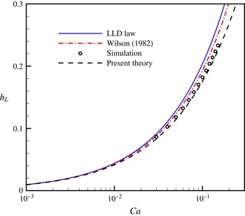
Under the lubrication approximations, the interface thickness,
 $h(y)$
, is once again governed by (3.6) to (3.8), but with
$h(y)$
, is once again governed by (3.6) to (3.8), but with
 $h_{T}$
replace by
$h_{T}$
replace by
 $h_{L}$
, which is not known a priori. To obtain a better comparison, the lubrication equation is numerically solved by shooting from the flat film toward the lower meniscus. The initial condition can be obtained via a formal linearization of the lubrication equation for small departures from the flat film, yielding
$h_{L}$
, which is not known a priori. To obtain a better comparison, the lubrication equation is numerically solved by shooting from the flat film toward the lower meniscus. The initial condition can be obtained via a formal linearization of the lubrication equation for small departures from the flat film, yielding
 $$\begin{eqnarray}h\approx h_{L}(1+{\it\eta}\text{e}^{-ky}),\end{eqnarray}$$
where
 $k=[3(\mathit{Ca}-h_{L}^{2})]^{1/3}/h_{L}>0$
; the free parameter
$k=[3(\mathit{Ca}-h_{L}^{2})]^{1/3}/h_{L}>0$
; the free parameter
 ${\it\eta}$
measures the amplitude of the perturbation with
${\it\eta}$
measures the amplitude of the perturbation with
 $0<{\it\eta}\ll 1$
for the situation of LLD film, and plays no role in the results presented. For fixed
$0<{\it\eta}\ll 1$
for the situation of LLD film, and plays no role in the results presented. For fixed
 $\mathit{Ca}$
, the film thickness
$\mathit{Ca}$
, the film thickness
 $h_{L}$
is adjusted until the asymptotic form of the meniscus (3.8) is satisfied. The exact solution of
$h_{L}$
is adjusted until the asymptotic form of the meniscus (3.8) is satisfied. The exact solution of
 $h_{L}$
as a function of
$h_{L}$
as a function of
 $\mathit{Ca}$
is shown in figure 11 as the dashed curve, which exhibits a better agreement with the diffuse-interface simulations. In addition, while the numerical simulations cannot extend to small values of
$\mathit{Ca}$
is shown in figure 11 as the dashed curve, which exhibits a better agreement with the diffuse-interface simulations. In addition, while the numerical simulations cannot extend to small values of
 $\mathit{Ca}$
, the three curves of lubrication theory collapse for
$\mathit{Ca}$
, the three curves of lubrication theory collapse for
 $\mathit{Ca}<10^{-2}$
, demonstrating the validation range of the LLD law as mentioned in previous work (e.g. Maleki et al.
Reference Maleki, Reyssat, Restagno, Quéré and Clanet2011). Finally, by fitting the numerical data, we propose a power law
$\mathit{Ca}<10^{-2}$
, demonstrating the validation range of the LLD law as mentioned in previous work (e.g. Maleki et al.
Reference Maleki, Reyssat, Restagno, Quéré and Clanet2011). Finally, by fitting the numerical data, we propose a power law
 $$\begin{eqnarray}h_{L}=0.759\mathit{Ca}^{0.621},\end{eqnarray}$$
which will be used later to predict the velocity of the capillary shock.
3.8 Capillary shock
As shown in figures 6 and 7, the capillary shock connecting the LLD film and the thick film in regime III propagates upwards linearly with time while maintaining a fixed shape. This leads to a well-defined velocity, similar with the contact line. Figure 8(a) also shows the variation of the propagation velocity of the capillary shock as a function of
 $\mathit{Ca}$
, which is smaller than the contact-line velocity. This type of solution has been well studied by Bertozzi et al. (Reference Bertozzi, Munch, Fanton and Cazabat1998) for a more general case in the presence of surface tension gradient. For completeness, we compare the numerical results with the lubrication theory, which admits stationary solutions of the interfacial thickness in a frame moving with the shock. The lubrication equation now has the form
$\mathit{Ca}$
, which is smaller than the contact-line velocity. This type of solution has been well studied by Bertozzi et al. (Reference Bertozzi, Munch, Fanton and Cazabat1998) for a more general case in the presence of surface tension gradient. For completeness, we compare the numerical results with the lubrication theory, which admits stationary solutions of the interfacial thickness in a frame moving with the shock. The lubrication equation now has the form
 $$\begin{eqnarray}{\it\kappa}^{\prime }-1+\frac{3}{h^{2}}\left({\rm\Delta}\mathit{Ca}-\frac{q}{h}\right)=0,\end{eqnarray}$$
where
 ${\rm\Delta}\mathit{Ca}=\mathit{Ca}-\mathit{Ca}_{cs}$
with
${\rm\Delta}\mathit{Ca}=\mathit{Ca}-\mathit{Ca}_{cs}$
with
 $\mathit{Ca}_{cs}$
the capillary number defined using the velocity of the capillary shock, and the flux can be related to either
$\mathit{Ca}_{cs}$
the capillary number defined using the velocity of the capillary shock, and the flux can be related to either
 $h_{T}$
or
$h_{T}$
or
 $h_{L}$
,
$h_{L}$
,
 $$\begin{eqnarray}q=h_{T}\left({\rm\Delta}\mathit{Ca}-\textstyle \frac{1}{3}h_{T}^{2}\right)=h_{L}\left({\rm\Delta}\mathit{Ca}-\textstyle \frac{1}{3}h_{L}^{2}\right)\!.\end{eqnarray}$$
Accordingly, the velocity of the capillary shock is completely determined by the thicknesses of the flat films,
 $h_{T}$
and
$h_{T}$
and
 $h_{L}$
, with
$h_{L}$
, with
 $$\begin{eqnarray}\mathit{Ca}_{cs}=\mathit{Ca}-{\rm\Delta}\mathit{Ca}=\mathit{Ca}-\textstyle \frac{1}{3}(h_{L}^{2}+h_{L}h_{T}+h_{T}^{2}),\end{eqnarray}$$
as has also been proposed in Snoeijer et al. (Reference Snoeijer, Delon, Fermigier and Andreotti2006). We seek solutions that are asymptotically flat far from the capillary shock, i.e.
 $$\begin{eqnarray}h(y)=\left\{\begin{array}{@{}ll@{}}h_{L}, & \text{as }y\rightarrow -\infty \\ h_{T}, & \text{as }y\rightarrow +\infty .\end{array}\right.\end{eqnarray}$$
For given values of
 $h_{L}$
and
$h_{L}$
and
 $h_{T}$
, the lubrication equation can be numerically solved via a shooting procedure from the LLD film to the thick one. As the initial condition, the linearly perturbed solution far below the capillary shock has the asymptotic form of a wavy interface, i.e.
$h_{T}$
, the lubrication equation can be numerically solved via a shooting procedure from the LLD film to the thick one. As the initial condition, the linearly perturbed solution far below the capillary shock has the asymptotic form of a wavy interface, i.e.
 $$\begin{eqnarray}h(y)\approx h_{L}\left[1+{\it\eta}_{1}\text{e}^{Ky}\cos (\sqrt{3}Ky)+{\it\eta}_{2}\text{e}^{Ky}\sin (\sqrt{3}Ky)\right]\quad \text{as }y\rightarrow -\infty ,\end{eqnarray}$$
where
 ${\it\eta}_{1}$
and
${\it\eta}_{1}$
and
 ${\it\eta}_{2}$
are the amplitudes of the two independent components, and
${\it\eta}_{2}$
are the amplitudes of the two independent components, and
 $$\begin{eqnarray}K=\frac{(h_{T}-h_{L})^{1/3}(h_{T}+2h_{L})^{1/3}}{2h_{L}},\end{eqnarray}$$
which is positive since
 $h_{T}>h_{L}$
. Note that the values of
$h_{T}>h_{L}$
. Note that the values of
 ${\it\eta}_{1}$
and
${\it\eta}_{1}$
and
 ${\it\eta}_{2}$
only act to shift the position of the capillary shock because of the translational invariance; the sole degree of freedom in this problem is the ratio
${\it\eta}_{2}$
only act to shift the position of the capillary shock because of the translational invariance; the sole degree of freedom in this problem is the ratio
 ${\it\eta}_{1}/{\it\eta}_{2}$
, which can be adjusted to fulfill the other boundary condition at the thick film. Moreover, one can alternatively shoot from the thick film towards the LLD film, employing a condition similar to (3.16). Obviously, this procedure would produce the same interfacial structure.
${\it\eta}_{1}/{\it\eta}_{2}$
, which can be adjusted to fulfill the other boundary condition at the thick film. Moreover, one can alternatively shoot from the thick film towards the LLD film, employing a condition similar to (3.16). Obviously, this procedure would produce the same interfacial structure.
Comparison of diffuse-interface simulation and lubrication theory for the capillary shock is made in figure 12. Representative interfacial profiles are illustrated in figure 12(a) for
 $\mathit{Ca}=0.04$
, corresponding to
$\mathit{Ca}=0.04$
, corresponding to
 $h_{L}=0.103$
. The two curves exhibit excellent agreement, for not only the primary structure but also the the small-amplitude capillary waves. A further comparison of the shock velocity
$h_{L}=0.103$
. The two curves exhibit excellent agreement, for not only the primary structure but also the the small-amplitude capillary waves. A further comparison of the shock velocity
 $\mathit{Ca}_{cs}$
is presented in figure 12(b), where the lubrication result is given by (3.14). This formula should be supplemented by a relation between
$\mathit{Ca}_{cs}$
is presented in figure 12(b), where the lubrication result is given by (3.14). This formula should be supplemented by a relation between
 $h_{L}$
and
$h_{L}$
and
 $\mathit{Ca}$
, e.g. the LLD law (1.1), as used in Snoeijer et al. (Reference Snoeijer, Delon, Fermigier and Andreotti2006). However, it is found that the LLD law will underestimate
$\mathit{Ca}$
, e.g. the LLD law (1.1), as used in Snoeijer et al. (Reference Snoeijer, Delon, Fermigier and Andreotti2006). However, it is found that the LLD law will underestimate
 $\mathit{Ca}_{cs}$
owing to the large
$\mathit{Ca}_{cs}$
owing to the large
 $\mathit{Ca}$
. Instead, we employed here a more accurate relation, (3.11), which well predicts the numerical data.
$\mathit{Ca}$
. Instead, we employed here a more accurate relation, (3.11), which well predicts the numerical data.

Figure 12. (a) Interfacial profiles around the capillary shock obtained by diffuse-interface simulations for
 $\mathit{Ca}=0.04$
(solid curve) and lubrication theory for
$\mathit{Ca}=0.04$
(solid curve) and lubrication theory for
 $h_{T}=0.242$
and
$h_{T}=0.242$
and
 $h_{L}=0.103$
(dashed curve). (b) Propagation velocity of the capillary shock,
$h_{L}=0.103$
(dashed curve). (b) Propagation velocity of the capillary shock,
 $\mathit{Ca}_{cs}$
, as a function of
$\mathit{Ca}_{cs}$
, as a function of
 $\mathit{Ca}$
. The solid curve corresponds to (3.14) with
$\mathit{Ca}$
. The solid curve corresponds to (3.14) with
 $h_{L}$
given by (3.11).
$h_{L}$
given by (3.11).
One might infer from figure 12(b) that the transition from regimes II to III occurs when the velocity of the capillary shock vanishes. We now show that this is not true because of the bifurcation behaviour of the transition. Using (3.14) together with (3.11), we have
 $\mathit{Ca}_{cs}=0.001$
at
$\mathit{Ca}_{cs}=0.001$
at
 $\mathit{Ca}=\mathit{Ca}_{c,2}=0.030$
. This small but still finite velocity is identified as the minimum velocity of the capillary shock in regime III. In fact, the stationary capillary shock can only theoretically exist at
$\mathit{Ca}=\mathit{Ca}_{c,2}=0.030$
. This small but still finite velocity is identified as the minimum velocity of the capillary shock in regime III. In fact, the stationary capillary shock can only theoretically exist at
 $\mathit{Ca}=\mathit{Ca}^{\ast \ast }$
rather than
$\mathit{Ca}=\mathit{Ca}^{\ast \ast }$
rather than
 $\mathit{Ca}_{c,2}$
, as discussed in § 3.6. On the other hand, we can alternatively calculate
$\mathit{Ca}_{c,2}$
, as discussed in § 3.6. On the other hand, we can alternatively calculate
 $\mathit{Ca}^{\ast \ast }$
based on the condition of the stationary capillary shock. By setting
$\mathit{Ca}^{\ast \ast }$
based on the condition of the stationary capillary shock. By setting
 $\mathit{Ca}_{cs}=0$
in (3.14) and using (3.11), it is easy to obtain
$\mathit{Ca}_{cs}=0$
in (3.14) and using (3.11), it is easy to obtain
 $\mathit{Ca}^{\ast \ast }=0.0286$
, which is close to the exact value 0.0281; the slight discrepancy is obviously owing to the inaccuracy of (3.11) to predict the thickness of the LLD film. Note that the minimum shock velocity can only be rationalized by lubrication theory, while it is too small to be resolved in our simulations.
$\mathit{Ca}^{\ast \ast }=0.0286$
, which is close to the exact value 0.0281; the slight discrepancy is obviously owing to the inaccuracy of (3.11) to predict the thickness of the LLD film. Note that the minimum shock velocity can only be rationalized by lubrication theory, while it is too small to be resolved in our simulations.
In addition to the minimum velocity, there exists a maximum velocity of the capillary shock, which is expected at the end of regime III (
 $\mathit{Ca}=\mathit{Ca}_{c,3}$
) where the shock tends to disappear. According to (3.14), this maximum velocity can be calculated using
$\mathit{Ca}=\mathit{Ca}_{c,3}$
) where the shock tends to disappear. According to (3.14), this maximum velocity can be calculated using
 $h_{L}=h_{T}$
, leading to
$h_{L}=h_{T}$
, leading to
 $\mathit{Ca}_{cs}=\mathit{Ca}_{c,3}-h_{T}^{2}=\mathit{Ca}_{c,3}-3\mathit{Ca}^{\ast }$
. Accordingly, the maximum velocity of the capillary shock with respect to the plate is identified as
$\mathit{Ca}_{cs}=\mathit{Ca}_{c,3}-h_{T}^{2}=\mathit{Ca}_{c,3}-3\mathit{Ca}^{\ast }$
. Accordingly, the maximum velocity of the capillary shock with respect to the plate is identified as
 $3\mathit{Ca}^{\ast }$
. Here we have used (3.5) to relate
$3\mathit{Ca}^{\ast }$
. Here we have used (3.5) to relate
 $h_{T}$
to
$h_{T}$
to
 $\mathit{Ca}^{\ast }$
.
$\mathit{Ca}^{\ast }$
.
3.9 Monotonic film
The threshold
 $\mathit{Ca}_{c,3}$
can be determined by
$\mathit{Ca}_{c,3}$
can be determined by
 $h_{L}=h_{T}=0.242$
together with (3.11), yielding
$h_{L}=h_{T}=0.242$
together with (3.11), yielding
 $\mathit{Ca}_{c,3}=0.16$
, which agrees with the numerical result (see figure 3). For larger values of
$\mathit{Ca}_{c,3}=0.16$
, which agrees with the numerical result (see figure 3). For larger values of
 $\mathit{Ca}$
, the case of two films connected by a steadily propagating capillary shock would not occur. In fact, it can be proved following Benilov, Benilov & O’Brien (Reference Benilov, Benilov and O’Brien2009) that the boundary-value problem, (3.12) to (3.15), has no solution when
$\mathit{Ca}$
, the case of two films connected by a steadily propagating capillary shock would not occur. In fact, it can be proved following Benilov, Benilov & O’Brien (Reference Benilov, Benilov and O’Brien2009) that the boundary-value problem, (3.12) to (3.15), has no solution when
 $h_{L}>h_{T}$
. Instead, it is expected to develop an unsteady rarefaction wave connecting the two flat films, as mentioned by Hocking (Reference Hocking2001) and discussed in more detail by Bertozzi et al. (Reference Bertozzi, Munch, Fanton and Cazabat1998) and Evans & Münch (Reference Evans and Münch2006) in the context of Marangoni-driven films. As illustrated in figure 13 for
$h_{L}>h_{T}$
. Instead, it is expected to develop an unsteady rarefaction wave connecting the two flat films, as mentioned by Hocking (Reference Hocking2001) and discussed in more detail by Bertozzi et al. (Reference Bertozzi, Munch, Fanton and Cazabat1998) and Evans & Münch (Reference Evans and Münch2006) in the context of Marangoni-driven films. As illustrated in figure 13 for
 $\mathit{Ca}=0.17$
, the present simulations show that the interface in regime IV evolves unsteadily and does not exhibit any non-monotonic behaviour of the film thickness with respect to
$\mathit{Ca}=0.17$
, the present simulations show that the interface in regime IV evolves unsteadily and does not exhibit any non-monotonic behaviour of the film thickness with respect to
 $y$
during the entire evolution period. However, the rarefaction wave is weak since the thicknesses of the two films are not well separated for the parameters considered. The film does tend to be uniform after sufficiently long time, and eventually develops a LLD-type film at larger
$y$
during the entire evolution period. However, the rarefaction wave is weak since the thicknesses of the two films are not well separated for the parameters considered. The film does tend to be uniform after sufficiently long time, and eventually develops a LLD-type film at larger
 $\mathit{Ca}$
.
$\mathit{Ca}$
.

Figure 13. Time evolution of the interface for
 $\mathit{Ca}=0.17$
in regime IV. (a) Corresponds to
$\mathit{Ca}=0.17$
in regime IV. (a) Corresponds to
 $t=10$
, and the time difference between successive panels is
$t=10$
, and the time difference between successive panels is
 ${\rm\Delta}t=13$
. Others are the same as figure 5.
${\rm\Delta}t=13$
. Others are the same as figure 5.
4 Concluding remarks
We have performed diffuse-interface simulations of film deposition on a partially wetting plate withdrawn vertically from a reservoir. With increasing
 $\mathit{Ca}$
, four different flow regimes were numerically identified based on the interfacial morphologies. When
$\mathit{Ca}$
, four different flow regimes were numerically identified based on the interfacial morphologies. When
 $\mathit{Ca}$
is less than a threshold
$\mathit{Ca}$
is less than a threshold
 $\mathit{Ca}_{c,1}$
, there is no film entrainment and the meniscus remains stationary with a fixed contact line. For
$\mathit{Ca}_{c,1}$
, there is no film entrainment and the meniscus remains stationary with a fixed contact line. For
 $\mathit{Ca}_{c,1}<\mathit{Ca}<\mathit{Ca}_{c,2}$
, the plate is coated by a thick film, which is connected to the reservoir through a dimple, and the classical LLD film cannot be formed; the thick film is determined by the moving contact line, with the thickness independent of the plate speed. An increase of
$\mathit{Ca}_{c,1}<\mathit{Ca}<\mathit{Ca}_{c,2}$
, the plate is coated by a thick film, which is connected to the reservoir through a dimple, and the classical LLD film cannot be formed; the thick film is determined by the moving contact line, with the thickness independent of the plate speed. An increase of
 $\mathit{Ca}$
above
$\mathit{Ca}$
above
 $\mathit{Ca}_{c,2}$
triggers the transition from the dimple to the LLD film, which is connected with the downstream thick film by a propagating capillary shock. Finally, a further increase of
$\mathit{Ca}_{c,2}$
triggers the transition from the dimple to the LLD film, which is connected with the downstream thick film by a propagating capillary shock. Finally, a further increase of
 $\mathit{Ca}$
above
$\mathit{Ca}$
above
 $\mathit{Ca}_{c,3}$
removes the capillary shock, leaving a film with a monotonic thickness. We thus provided a rather detailed understanding of the film deposition and transition in dip coating. Specifically, our simulations reproduced the film structures observed in the experiments of Snoeijer et al. (Reference Snoeijer, Delon, Fermigier and Andreotti2006, Reference Snoeijer, Ziegler, Andreotti, Fermigier and Eggers2008). The interfacial profiles in the first three flow regimes can be analysed in a piecewise way, and comparison with available lubrication theory shows favourable agreements.
$\mathit{Ca}_{c,3}$
removes the capillary shock, leaving a film with a monotonic thickness. We thus provided a rather detailed understanding of the film deposition and transition in dip coating. Specifically, our simulations reproduced the film structures observed in the experiments of Snoeijer et al. (Reference Snoeijer, Delon, Fermigier and Andreotti2006, Reference Snoeijer, Ziegler, Andreotti, Fermigier and Eggers2008). The interfacial profiles in the first three flow regimes can be analysed in a piecewise way, and comparison with available lubrication theory shows favourable agreements.
The numerical results indicate that the onset of film deposition occurs when the apparent contact angle vanishes, confirming the criteria widely accepted for the dynamic wetting transition of receding contact lines. However, the predicted critical capillary number for the onset of film deposition,
 $\mathit{Ca}_{c,1}$
, is larger than the experimentally observed one,
$\mathit{Ca}_{c,1}$
, is larger than the experimentally observed one,
 $\mathit{Ca}^{\ast }$
. This raises the question of whether the thick film can be realized in a two-dimensional theoretical or numerical model, and the answer obviously depends on the relative magnitude of
$\mathit{Ca}^{\ast }$
. This raises the question of whether the thick film can be realized in a two-dimensional theoretical or numerical model, and the answer obviously depends on the relative magnitude of
 $\mathit{Ca}_{c,1}$
and
$\mathit{Ca}_{c,1}$
and
 $\mathit{Ca}_{c,2}$
. If the former is larger, the thick film cannot occur and the instability of the meniscus will directly result in the formation of the LLD film. Our numerical results show the opposite case with
$\mathit{Ca}_{c,2}$
. If the former is larger, the thick film cannot occur and the instability of the meniscus will directly result in the formation of the LLD film. Our numerical results show the opposite case with
 $\mathit{Ca}_{c,1}<Ca_{c,2}$
, which still allows the occurrence of the thick film in a two-dimensional model.
$\mathit{Ca}_{c,1}<Ca_{c,2}$
, which still allows the occurrence of the thick film in a two-dimensional model.
It has been shown by Snoeijer et al. (Reference Snoeijer, Andreotti, Delon and Fermigier2007) and Chan et al. (Reference Chan, Snoeijer and Eggers2012) that the coating transition corresponds to a saddle-node bifurcation of the stationary meniscus. Our numerical results show that the bifurcation causes the formation of the thick film rather than the LLD one. Instead, the onset of the LLD film is triggered by a bifurcation of the dimple solution. Based on lubrication theory, we identified multiple branches of dimple solutions and a series of bifurcations around
 $\mathit{Ca}^{\ast \ast }$
, a capillary number smaller than
$\mathit{Ca}^{\ast \ast }$
, a capillary number smaller than
 $\mathit{Ca}_{c,2}$
. The bifurcations of the stationary meniscus and the dimple are accompanied by discontinuities associated with the propagating velocities and profiles of the interfacial structures. Specifically, both the contact line and the capillary shock have a non-zero propagating velocity in the laboratory frame, as long as they move. In addition, the transition of the interfacial profiles from the dimple to the LLD film also occurs in a discontinuous way.
$\mathit{Ca}_{c,2}$
. The bifurcations of the stationary meniscus and the dimple are accompanied by discontinuities associated with the propagating velocities and profiles of the interfacial structures. Specifically, both the contact line and the capillary shock have a non-zero propagating velocity in the laboratory frame, as long as they move. In addition, the transition of the interfacial profiles from the dimple to the LLD film also occurs in a discontinuous way.
However, the mechanism of the precritical transition experimentally observed by Snoeijer et al. (Reference Snoeijer, Delon, Fermigier and Andreotti2006) remains yet unknown. Delon et al. (Reference Delon, Fermigier, Snoeijer and Andreotti2008) suggested two potential explanations: the presence of contact angle hysteresis or the edge of the plate used in the experiments. While the contact angle hysteresis can be incorporated in the calculations following the procedure of Ding & Spelt (Reference Ding and Spelt2008), the side edges of the plate cause a curved contact line and render the flow three-dimensional. A detailed inspection of these effects is beyond the scope of the present work and deserves further investigation.
Acknowledgements
We acknowledge the anonymous referees to improve the manuscript. P.G. was supported by NSFC (grant numbers 11102203 and 11422220), the Chinese Academy of Sciences (grant number KJZD-EW-J01), the Foundation for the Author of National Excellent Doctoral Dissertation of PR China (grant number 201136), Youth Innovation Promotion Association CAS, and the Fundamental Research Funds for the Central Universities. J.J.F. was supported by NSERC (grant number 05862) and the Canada Research Chair Program.


