


1. Introduction
Spin coating is a widespread film fabrication technique in research and industry (Soto-Montero, Soltanpoor & Morales-Masis Reference Soto-Montero, Soltanpoor and Morales-Masis2020). It can conveniently and consistently produce a thin film with less than 1 % variation in thickness due to self-levelling of the liquid film (Frank et al. Reference Frank, Rao, Despotopoulou, Pease, Hinsberg, Miller and Rabolt1996). In spin coating, a small volume of coating material is dispensed onto a substrate, which is either already spinning (dynamic) or subsequently set to spin (static). Dynamic spin coating is often preferred because it requires less coating material than its static counterpart (Tyona Reference Tyona2013). Moreover, for coating of multiple layers, dynamic spin coating reduces the re-dissolving of the previous layer if the solvents are not strictly orthogonal (Yang, Kang & Kim Reference Yang, Kang and Kim2017).
Many publications have helped to establish a profound understanding of the fluid dynamics of spin coating (Emslie, Bonner & Peck Reference Emslie, Bonner and Peck1958; Schwartz & Roy Reference Schwartz and Roy2004; Craster & Matar Reference Craster and Matar2009; Primkulov et al. Reference Primkulov, Pahlavan, Bourouiba, Bush and Juanes2020), such as effects of fingering instabilities (Melo, Joanny & Fauve Reference Melo, Joanny and Fauve1989; Sahoo, Orpe & Doshi Reference Sahoo, Orpe and Doshi2018), non-Newtonian fluids (Lawrence & Zhou Reference Lawrence and Zhou1991), and solvent evaporation (Arscott Reference Arscott2020). However, the majority of prior works have focused on static dispensing, where the inertial effect of the landing drop on the spinning substrate is excluded. For impact of drops on static substrates, the Weber number  $We = \rho u_0^2{R_0}/\gamma $ (u 0, ρ and γ are respectively the impact velocity, density and surface tension of the liquid drop) describes the relative importance between the inertial and capillary effect and identifies deformation and spreading behaviours (Josserand & Thoroddsen Reference Josserand and Thoroddsen2016; Yonemoto & Kunugi Reference Yonemoto and Kunugi2017; Srivastava & Kondaraju Reference Srivastava and Kondaraju2020). In the dynamic spin-coating process, the Weber number also plays an important role, while its influence on the spreading process is still unclear. Moreover, the centrifugal effect for a spinning and spreading film of angular velocity ω should be considered. Because the characteristic pressure due to centrifugal acceleration is ρω 2R 2 (R is the film radius) and the capillary pressure is ~γ/h (h is the film thickness), one can define the rotational Bond number as the ratio between the two quantities (Melo et al. Reference Melo, Joanny and Fauve1989; Wang & Chou Reference Wang and Chou2001),
  $B{o_r} = \rho {\omega ^2}{r^2}h/\gamma = \rho {\omega ^2}V/\gamma$, with V being the drop volume. Here, Bor determines the critical radius Rc for the onset of fingering instability (Wang & Chou Reference Wang and Chou2001), and the radius of the final film should be smaller than Rc to avoid fingering defects.
Another important challenge in applications of dynamic spin coating is to maintain the axisymmetry of the spreading droplet. Several experimental studies have been conducted of these non-axisymmetrically spreading cases (Li et al. Reference Li, Yuan, Han and Xi2011; Moghtadernejad et al. Reference Moghtadernejad, Jadidi, Johnson, Stolpe and Hanson2021). A bulk of waved liquid can be observed during spreading, which, however, is hazardous for film fabrication. In this paper, we design an experimental system to achieve axisymmetric dynamic spin coating. We aim to explore the influence of We and Bor during the axisymmetric spreading process. We carefully measure the film radius and film thickness as functions of time t with a high-speed camera and fluorescence photography. We consider the energy budget that offers insights into the spreading dynamics.
2. Methods
2.1. Experimental methods
As schematically depicted in figure 1, the liquid drop was dispensed from the tip of a vertically oriented nozzle by a syringe pump. We chose ethanol as its surface tension is similar to that of many common organic solvents used in spin coating of thin films, and the results will be more relevant. The inner and outer diameters of the nozzle were 0.4 and 0.7 mm, respectively. Depending on the wetting diameter at the nozzle (Tsai & Wang Reference Tsai and Wang2019), the drop radius R 0 was approximately a constant of 1.13 ± 0.04 mm in our experiments. Accordingly, the gravitational Bond number  $Bo = \rho gR_0^2/\gamma \approx 0.45$. The substrate was a glass or silicon (covered by SiO2) disk of 15 mm in diameter, which was attached to an electric motor. The disk radius was less than Rc (~8 mm) to avoid a fingering instability. Care was taken to ensure that the drop impacts at the centre of the rotating disk. The Weber number was changed by adjusting the release height of the drop (from 2 mm to 10 cm). Taking our targeted applications as an example, we are interested in the fabrication of organic photovoltaics using dynamic spin coating. One frequently used solvent is chloroform, whose surface tension is slightly larger than that of ethanol. The volume of the solution drop for spin coating is ~8 μl and the drop is typically released at a height of a few centimetres (1–5 cm). The corresponding Weber number ranges from 13 to 67, which is covered by the present work. The value of Bor spans from 10 to 65 via varying ω from 2000 to 5000 rpm.

Figure 1. Schematic of experimental configuration of dynamic spin coating.
The dynamic spin-coating process was recorded from oblique (with an angle of 45° to the horizontal plane) and side views using two synchronized high-speed cameras (i-SPEED 220, iX-cameras) and illuminated by two light-emitting diode light sources. The cameras were coupled with long-working-distance microscope lenses of adjustable magnifications. The typical frame rate was 4000 frames per second with an exposure time of 2 μs. The substrates were cleaned subsequently using lye, deionized water, acetone and isopropanol in an ultrasonic bath (each step for 15 min). Then the substrates were treated by oxygen plasma for 1 min. Each substrate was used only once for the dynamic spin-coating process before being retreated by plasma. The measured static contact angle for ethanol was below 10° for both the glass and SiO2-covered silicon substrates.
Figure 2 shows snapshots of dynamic spin coating from the oblique and side views. A droplet of 6 μl was released at a height of ~1 cm. As the droplet impacts the substrate and spreads radially, a thin inner film is formed in the middle with a capillary ridge around the perimeter. The spreading radius R, ridge width w and ridge height hr were measured using the edge detection code with MATLAB. The impact velocity and Weber number can also be obtained from the side view (u 0 = 0.53 m s−1 and We = 10 in figure 2).

Figure 2. Snapshots of the dynamic spin-coating process obtained from (a) camera 1 and (b) camera 2, with an ethanol drop of 1.13 mm in radius and the rotating speed being 3000 rpm.
2.2. Measurement of the film profile
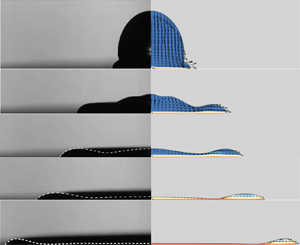
The measurement of the inner film thickness is rather challenging due to the fast spreading and view blockage by the ridge. To overcome this challenge, fluorescence photography (Alekseenko et al. Reference Alekseenko, Cherdantsev, Cherdantsev, Isaenkov, Kharlamov and Markovich2012) was used. A fluorescent dye, rhodamine 6G (Rh6G), was doped in the liquid with a concentration of 0.3 mg ml−1. The surface tension of this solution was measured as 22.0 mN m−1, within 3 % of the value of pure ethanol. Excited by ultraviolet light, the Rh6G-doped drop emits a luminosity field I(r), as shown in figure 3. The overall three-dimensional morphology of the spreading drop is reconstructed via image processing based on I(r) with MATLAB (figure 3b). Because of its axisymmetry, the centreline profile of the film (denoted by the red curve) is extracted for further analysis (e.g. film volume calculations), instead of the whole three-dimensional surface. By this means, the distortion due to the tilted camera view on surface height reconstruction (especially the outer area of the ridge) is minimized. For thin films (h < 1 mm), I(r) is linearly proportional to thickness by the Beer–Lambert law:  $h = cI(r)$, with c being the proportionality constant (Alekseenko et al. Reference Alekseenko, Cherdantsev, Cherdantsev, Isaenkov, Kharlamov and Markovich2012; Wang et al. Reference Wang, Zhang, Xia, Xie and Deng2022). An intuitive but sketchy method to determine c is comparing the ridge height hr from the side-view shadowgraph and the corresponding value of I(r) from fluorescence photography. Instead, we obtained c through calibration of the spreading drop volume,
  $V = \int_0^R {2{\rm \pi} rh\,\textrm{d}r} = 2{\rm \pi} c\Delta r\sum\nolimits_i {{r_i}{I_i}} = cV^{\prime}$, where c is indeed the averaged value along the radial direction, Δr is the sampling distance and V′ is the integrated volume based on I(r). As shown in figure 4(a), the time-averaged value of c is achieved through comparison with the original drop volume (6 μl), with an error of ±1 μl, which is due to uncertainty associated with the measurements and limitation of image resolutions. Figure 4(b) further verifies the accuracy in thickness measurement by comparing hr with the values obtained from the side-view shadowgraph method for both the mixture and pure ethanol cases.

Figure 3. (a) Image sequences of the spreading drop based on the fluorescence intensity. (b) Film thickness profile based on the brightness of the fluorescence extracted from the image (at 9 ms).

Figure 4. (a) Calibration of the fluorescence method by correlating the integrated volume with the original drop volume (6 μl); the mean value of the coefficient c is denoted by the horizontal solid line being the averaged value, and the dashed lines represent the lower and upper 95 % of confidence intervals (CI), respectively. (b) Evolution of the ridge height obtained from the fluorescence methodology and the side-view shadowgraph at We = 10 and Bor = 23.4. The error bars represent uncertainty associated with the measurements and limitation of image resolution.
2.3. Numerical simulation method
We perform numerical simulations of the dynamic spin-coating process using the open-source software Basilisk (Popinet et al. Reference Popinet2013–2021b), which is a finite-volume solver for the incompressible two-phase Navier–Stokes equations (Popinet Reference Popinet2009, Reference Popinet2015). It reconstructs the liquid–gas interface using the volume-of-fluid method based on a momentum-conserving scheme and incorporates the surface tension as a body force. The adaptive mesh refinement scheme allows one to save computing cost while resolving the multiscale problem involved in the spin-coating process. The characteristic length scale reduces from millimetres to micrometres while the drop impacts and continuously spreads on the solid substrate. Since the Coriolis force  $2\omega {u_\varphi } \approx \rho r{\omega ^3}{h^2}/\mu $ (uφ is the azimuthal velocity and μ is the liquid viscosity) is much smaller than the centrifugal force
  $r{\omega ^2}$ (Emslie et al. Reference Emslie, Bonner and Peck1958), it is neglected in this work. Other non-axisymmetric effects such as fingering instabilities and heterogeneous wetting on the substrate are also ignored. The evaporation effect on the spreading dynamics is also neglected, as the time scale for an evident volume loss due to evaporation is over two orders of magnitude (> seconds) larger than that of the spreading process (Gurrala et al. Reference Gurrala, Katre, Balusamy, Banerjee and Sahu2019).
A governing equation in the azimuthal (φ) direction is included (Yang et al. Reference Yang, Delbende, Fraigneau and Martin Witkowski2020), and the acceleration term due to spinning is incorporated in the governing equation to account for the centrifugal effect (Popinet et al. Reference Popinet2013–2021a). The size of the computational domain is 8 × 8 mm2. The mesh is refined to level 11 so that the finest cell is 3.9 μm. The film thickness is about 20 μm when the drop is fully spread on the substrate, thus occupying five mesh cells. The bottom is no-slip boundary condition except the area in the vicinity of the liquid–solid interface (contact line) where the Robin boundary condition is applied. Because no-slip condition creates force singularity at the liquid–solid interface and phenomenologically traps a thin air film (<1 μm) between the drop and substrate that consistently impedes the contact of them, which is not observed in experiments. The Robin boundary condition is  ${\boldsymbol{u}_t} = {u_s} - \lambda (\partial {\boldsymbol{u}_t}/\partial n)$, with ut the tangential velocity at the boundary, us the substrate velocity, λ the slip length and n the inward normal to the surface. For simplicity, we set λ to be a constant of 1 μm, which is large enough to avoid such an unreal air film in our simulations. For the wetting condition, we employ an empirical dynamic contact angle model developed by Kistler (Reference Kistler1993) based on Hoffman's law (Hoffman Reference Hoffman1975). This dynamic angle θ is a function of the equilibrium contact angle θeq and the capillary number Ca regarding the contact line spreading velocity ucl, written as
 \begin{equation}\theta = {f_{Hoff}}[Ca + f_{Hoff}^{ - 1}({\theta _{eq}})],\end{equation}
with  $Ca = \mu {u_{cl}}/\gamma $ and
  $f_{Hoff}^{ - 1}$ being the inverse function of Hoffman's empirical function (Hoffman Reference Hoffman1975), which is defined as
 \begin{equation}{f_{Hoff}}(x) = \arccos \left\{ {1 - 2\tanh \left[ {5.16{{\left( {\frac{x}{{1 + 1.31{x^{0.99}}}}} \right)}^{0.706}}} \right]} \right\},\end{equation}
with  $x = Ca + f_{Hoff}^{ - 1}({\theta _{eq}})$. The contact line velocity ucl is obtained by numerical differentiation of the wetting radius R, namely
  ${u_{cl}} = \textrm{d}R/\textrm{d}t$. Although Kistler's model was fitted from data where inertia can be ignored, the data still fall right on the model curve even when the Reynolds number is up to 250 as reported by Kistler. Kistler also reported the model fits well over the range 0.005 < Ca < 0.3, which is satisfied in the present work.
2.4. Validation of the numerical simulation
The numerical simulation is validated by comparing with experimental results. Figure 5 shows details of the spreading droplet obtained from side-view image sequences (left-hand panel), numerical simulations (right-hand panel) and the fluorescence method (dashed curves). For consistency, the initial drop profile in the simulation was extracted from that of the experiment, which was vertically prolate with the aspect ratio being 1.15. A qualitative comparison of the droplet profile demonstrates that this numerical method can capture the flow features of the spin-coating process, and also validates the accuracy of the thickness measurement using the fluorescence method. The velocity fields and contours of the rotation speed show that the drop deformation is dominated by the inertia of the free fall after impingement, similar to those of static substrate counterparts. An air bubble is trapped beneath the drop after impingement in simulations, as also found in figure 3. The bubble remains stationary in the drop centre and then bursts when the spreading velocity reaches the minimum (at ~15 ms), after which spreading is dominated by the centrifugal force (details are discussed in the next section). It is noted that the drop always oscillates after pinching off from the nozzle as observed in experiments. The aspect ratio (vertical width a to horizontal width b) of the drop in our experiments is within (0.85, 1.2). Our simulations comparing droplets of different aspect ratios demonstrate that the oscillation/deformation of the drop only contributes slightly at the early stage after impact and negligibly on the transition of the stages and centrifugal thinning stage, as shown in figure 6. Therefore, for simplicity we initialize the drop as a sphere in further simulations.

Figure 5. Comparison of a spreading ethanol drop shape obtained from experimental images and simulation results when We = 10, Bor = 23.4. The dashed curves show the liquid–air interfaces from the fluorescence method.

Figure 6. Comparison of the spreading radius at three vertical aspect ratios, 0.87, 1 (sphere) and 1.15, when Bor = 23.4 and We = 10.
The quantitative comparison (figure 7) of the corresponding dynamic contact angle and contact line moving velocity during spreading also demonstrates the good consistency between the experiment and simulation. The dynamic contact angle is positively correlated with the spreading velocity, as given by (2.1). Angle θ decreases rapidly after impacting and reaches a minimum value of 42° when ucl ≈ 0.1 m s−1, after which θ gradually increases to ~60° when reaching the disk edge.

Figure 7. Comparison of the dynamic contact angle and spreading velocity under the conditions corresponding to figure 5.
3. Results and discussion
3.1. Evolution of the spreading radius throughout the dynamic spin-coating process
The dynamic spin-coating process can be divided into two stages: (I) inertial spreading stage and (II) centrifugal thinning stage. The first stage begins immediately after drop impingement (figure 5): the bottom of the drop is sheared by the rotating substrate, while the upper part still descends due to inertia of free fall. In this stage, the spreading is mainly affected by the factors similar to classical drop impingement onto a stationary substrate, such as the Weber number, viscosity and contact angle on the substrate. The rotational motion of the substrate is transferred upwards due to viscous shearing. Since the liquid film is continuously accelerated in the azimuthal direction, it enters the centrifugal thinning stage after a certain period.
Figure 8 shows the time evolution of the spreading film radius obtained in experiments and those from simulations at various We and Bor. The time is normalized by the capillary time  ${t_c}$ and the spreading radius is normalized by R 0. In general, the spreading time decreases with increased We and Bor. At the early stage after drop impingement, R(t) exhibits a steep slope, demonstrated as a function of the Weber number. The rotational Bond number has marginal effects on the spreading radius evolution during this stage, which is also confirmed by the velocity fields in figure 5. The spreading radius here follows a square-root dependence, R ~ t 1/2, even when the gravitational Bond number varies. This observation is similar to that for drops impacting on stationary substrates (Josserand & Thoroddsen Reference Josserand and Thoroddsen2016). In that case, a maximum wetting radius exists before the drop retracts (Yonemoto & Kunugi Reference Yonemoto and Kunugi2017). Correspondingly, a transient spreading radius (marked by the dashed lines) exists here when the spreading velocity reaches the minimum due to viscous dissipation and interaction with the substrate. The time required for the film spreading to the transient radius (Rt) is positively correlated with the Weber number, while independent of Bor. The transition from stage I to II is demarcated by the black dashed line. In stage II, the centrifugal force becomes increasingly important and is responsible for further expanding of the film. It is also found that Bo plays a role in the spreading velocity but not the general trend. For a small Bo, i.e. a drop smaller than the capillary length scale, this role is minor.

Figure 8. Time evolution of the drop spreading radius at (a) various Bor numbers when We = 10 and (b) various We numbers when Bor = 23.4. The error bars represent uncertainty associated with the measurements of the spreading radius. Here, Bo = 0.45 and R 0 = 1.13 mm if not specified.
3.2. Evolution of the spreading radius and film thickness in the centrifugal thinning regime
In the spreading regime where centrifugation dominates, the spreading radius R and film thickness h are functions of ω and fluid properties. Following Melo's principle (Melo et al. Reference Melo, Joanny and Fauve1989), R and t are normalized by  $R^{\prime} = {V^{1/3}}B{o_r}$ and
  $t^{\prime} = {V^{1/3}}\mu /\gamma $, respectively. It should be noted that R′ and t′ are different from the original expressions in the work of Melo et al., while still satisfying the Buckingham
  ${\rm \pi}$ theorem,
  $R/R^{\prime} = f(t/t^{\prime},B{o_r})$. Figure 9 replots the extracted data in the centrifugal thinning regime at different We and Bor from figure 8. A power-law fitting with the scaling exponent being 1.2 ± 0.001 is obtained. This correlation deviates significantly from asymptotic scaling (Fraysse & Homsy Reference Fraysse and Homsy1994; Oron, Davis & Bankoff Reference Oron, Davis and Bankoff1997), R ~ t 1/4, whose second derivative is negative rather than positive as observed in our experiments and simulations. This is because the previous asymptotic scaling was derived from the lubrication theory based on the assumption of a flat film. Indeed, a capillary ridge is formed and accounts for a large portion of the spreading film as seen in figures 2 and 3. Considering the spreading is dominated by centrifugation, the scaling of R ~ t 1.2 is reasonable and helps to explain the nearly constant contact line moving velocity in the later stage of drop spreading when the viscous effect becomes more important.

Figure 9. Normalized spreading radius R/R′ as a function of the dimensionless time t/t′.
Figure 10 depicts the normalized inner film thickness versus the dimensionless time. The thinning of the film asymptotically follows the classical power law, i.e. h ~ t −1/2, where the viscous shear force balances the centrifugal force, and surface tension is neglected (Oron et al. Reference Oron, Davis and Bankoff1997). A possible explanation is that the flow in the inner film satisfies the lubrication approximation in the developed stage of the centrifugal thinning regime. For instance, at t = 21 ms in figure 5, the inner film becomes very thin and flat, and the profile of the radial velocity in the vertical direction is parabolic. We noticed that in the prior work by Middleman (Reference Middleman1987), the film-thinning scaling exponent is −1, where the effect of the air shear stress is considered. Following Middleman's definitions and derivation, a dimensionless time τ and a dimensionless film thickness H are given as  $\tau = (2\rho {\omega ^2}h_0^2/3\mu )t$ and
  $H = h(t)/{h_0}$, where h 0 is the initial uniform thickness of the film. The correlation between the dimensionless film thickness H and time τ is expressed as
 \begin{equation}\tau = \beta \left( {\left. {\frac{1}{H} - 1} \right)} \right. - {\beta ^2}\ln \left( {\left. {\frac{{1 + \beta H}}{{H(1 + \beta )}}} \right)} \right.,\end{equation}
where the dimensionless parameter  $\beta = 4{h_0}{\omega ^{1/2}}\rho /(3{\rho _{air}}\nu _{air}^{1/2})$, with ρair and νair being the density and kinetic viscosity of air. In most applications, β is large (of the order of 102 to 103 in the current work). In Middleman's work, the second term is considered to approach zero, yielding
  $\tau \sim {H^{ - 1}}$. However, we find that the second term cannot be neglected. With the logarithm term in (3.1) being expanded into a Taylor series to the second order, it can be rewritten as
 \begin{equation}\tau \approx \frac{\beta }{{\beta + 1}}\left( {\frac{1}{H} - 1} \right) + \frac{{{\beta ^2}}}{{{{({1 + \beta } )}^2}}}\frac{{{{({1 - H} )}^2}}}{{2{H^2}}}.\end{equation}
Therefore, even considering the air-shear effect, the thinning of the inner film still satisfies  $H\sim {\tau ^{ - 1/2}}$ for a large β, rather than
  $H\sim {\tau ^{ - 1}}$.

Figure 10. Normalized inner film thickness h/h 0 plotted against the dimensionless time t/t 0 at various Bor numbers when We = 10. The triangle represents the slope of the black line. The error bars represent uncertainty associated with the measurements of the film thickness.
3.3. Energy budget analysis
Analysis of the energy budget is an approach commonly used to study energy partition and transformation (Lee et al. Reference Lee, Derome, Guyer and Carmeliet2016; Ye, Yang & Fu Reference Ye, Yang and Fu2016; Huang & Chen Reference Huang and Chen2018; He, Xia & Zhang Reference He, Xia and Zhang2019; Sanjay, Lohse & Jalaal Reference Sanjay, Lohse and Jalaal2021). Film spreading on a spinning substrate is governed by the balance between kinetic energy (Ek), surface energy (Es), gravitational potential energy (Eg), viscous dissipated energy (EΦ) and shear work (Eτ) imposed on the drop by the rotating substrate. We trace the evolution of the energy sources to give an insight into the dynamics during the spin-coating process by showing how it experiences the transition of spreading regimes. The energy equation for the axisymmetric dynamic spin-coating process is
 \begin{equation}{E_{k1}} + {E_{s1}} + {E_{g1}} = {E_{k2}} + {E_{s2}} + {E_{g2}} + {E_\varPhi } - {E_\tau },\end{equation}
where subscripts 1 and 2 denote the time at drop impact and an arbitrary moment during spreading, respectively. Term Eg is neglected in the energy budget analysis during spreading, as Bo < 1 and the initial gravity potential at the release height is almost converted into kinetic energy at impact. Each term is written as follows:
 \begin{gather}{E_k} = {E_{kr}} + {E_{k\varphi }} + {E_{kz}} = \frac{1}{2}{\int_V {|\boldsymbol{u}|} ^2}\,\textrm{d}V,\end{gather}
 \begin{gather}{E_s} = \gamma {A_{lg}} + {E_{ls}},\end{gather}
 \begin{gather}{E_\varPhi } = \int_{{t_1}}^{{t_2}} {\int_V {\varPhi \,\textrm{d}V\,\textrm{d}t} } ,\end{gather}
 \begin{gather}{E_\tau } = \int_{{t_1}}^{{t_2}} {{\boldsymbol{F}_{\tau (r,\varphi )}}\boldsymbol{\cdot }{\boldsymbol{u}_{(r,\varphi )}}\,\textrm{d}t} ,\end{gather}
with Ekr, Ekφ and Ekz being the kinetic energy in the radial (r), azimuthal (φ) and axial (z) directions,  $\boldsymbol{u} = ({u_r},{u_\varphi },{u_z})$ the velocity vector, Alg the liquid–air interface area, Φ the viscous dissipation rate and
  ${\boldsymbol{F}_{\tau (r,\varphi )}} \approx \mu \int_{{A_{ls}}} {(\partial {u_r}/\partial z,\partial {u_\varphi }/\partial z){|_{z = 0}}r\,\textrm{d}{A_{ls}}}$ the shear force vector at the liquid–solid interface (Als) at the wall z = 0. Parameter Els is the surface energy at the liquid–solid interface and contact line and obtained from (3.3). The dissipation due to capillary hysteresis is not considered, as this effect occurs only when the substrate is swept by both an advancing and a receding contact line (Yue Reference Yue2020).
Figure 11 shows representative examples of the energy budget evolution obtained from simulations. The energy terms are normalized by the total energy  ${E_{total}} = {E_k} + {E_s} + {E_\varPhi }$, which increases continuously due to the input energy Eτ. Initially, upon drop impact (t = 0 ms), the drop's energy is stored as surface energy Es and kinetic energy Ekz (~60 % of Etotal for We = 10, and ~90 % for We = 65). After impingement, Ekz is rapidly converted to Es, Ekr, and partially consumed by viscous dissipation EΦ, as the drop spreads in the radial direction. The larger the Weber number, the higher the portion of Ekr that is reached. For We = 65, Ekr reaches ~40 % of the total energy after growth for a short duration (~1 ms) and then declines to a low level (<5 %) at the transient state. Meanwhile, the surface energy increases rapidly and eventually dominates during the transient state. The higher the value of We, the higher the percentage the surface energy reaches (>70 % for We = 65), as the drop spreads faster and further. The proportion of the viscous dissipation in the total energy budget is positively correlated with We and Bor due to stronger viscous shear from the rotating disk. This is consistent with the finding for a drop impacting on a stationary substrate in that viscous dissipation increases with impact velocity (Lee et al. Reference Lee, Derome, Guyer and Carmeliet2016).

Figure 11. Energy budget for the dynamic spin-coating process with (a) We = 10, Bor = 23.4, (b) We = 65, Bor = 23.4 and (c) We = 10, Bor = 65.
After the transient state, Ekφ increases monotonically, and the film spreading enters the centrifugal thinning stage. The bulk liquid is continuously accelerated in the azimuthal direction due to shearing from the substrate. Consequently, the velocity in the radial direction is increased. However, due to the countering viscous stress from the substrate and thinning of the film, Ekr accounts for less than 5 % of the total energy. During the centrifugal thinning stage, Es continues rising, approximately as  ${E_s}\sim {R^2}$. However, the percentage of Es to Etotal decreases, as Ekφ increases more rapidly due to the azimuthal acceleration of the bulk liquid and increasing spreading radius (also ~R 2).
3.4. Radius at transition from inertia to centrifugal regime
Analogous to the case of drop impingement on a static substrate (Srivastava & Kondaraju Reference Srivastava and Kondaraju2020), there exists a transient state at Rt for the dynamic spin-coating process when the radial spreading velocity ucl = dR(t)/dt reaches the minimum. Figure 12 shows the spreading velocity against the dimensionless spreading radius by changing either Bor or We. The results indicate that Bor has marginal effects on Rt. For larger Weber numbers, Rt increases. During the initial impact stage, the relationship between Rt and We is similar to that of drops impacting on stationary substrates.

Figure 12. Radial spreading velocity (contact line moving velocity) plotted against the dimensionless spreading radius at different (a) Bor when We = 10 and (b) We when Bor = 23.4. The inset shows a comparison of the dimensionless transient radius of (3.8) with the simulated data. The error bars represent uncertainty associated with the measurements of the spreading radius.
Many researchers have developed models for such R versus We based on energy conservation without considering the rotational shearing work from the substrate (Clanet et al. Reference Clanet, Béguin, Richard and Quéré2004; Attané, Girard & Morin Reference Attané, Girard and Morin2007; Roisman Reference Roisman2009; Josserand & Thoroddsen Reference Josserand and Thoroddsen2016; Lee et al. Reference Lee, Derome, Guyer and Carmeliet2016; Yonemoto & Kunugi Reference Yonemoto and Kunugi2017; Srivastava & Kondaraju Reference Srivastava and Kondaraju2020). If we assume an infinitely large Weber number, the effect of the rim can be neglected, and the film thickness is approximately uniform. Accordingly, the magnitude of Rt is similar to the scaling relationship  ${R_t}\sim R{e^{1/5}}\sim W{e^{1/10}}$, as obtained for the case where a drop impacts a static substrate (Clanet et al. Reference Clanet, Béguin, Richard and Quéré2004), where
  $Re = 2\rho {u_0}{R_0}/\mu $ is the Reynolds number. However, the Weber number is finite and as found in figure 13 the volume of the rim cannot be ignored. In previous work (Roisman Reference Roisman2009), a characteristic length
  ${L_R}\sim R{e^{2/5}}W{e^{ - 1/2}}$ is incorporated to account for the influence of the rim motion, which should be inversely correlated with Rt. As shown in the inset of figure 12(b), we fit the obtained data using the linear combination of the two terms following Roisman's method, leading to a semiempirical relation:
 \begin{equation}R/{R_0} \approx 1.03\ R{e^{1/5}} - 0.08\ R{e^{2/5}}\ W{e^{ - 1/2}}.\end{equation}
It is found that the coefficient of the second term on the right-hand side of (3.8) is much smaller than that of the first term. This indicates that the role of the rim is less important during spreading, for 886 < Re < 2553 and 10 < We < 83 in this work.

Figure 13. Evolution of the ridge volume ratio at (a) various Bor when We = 10 and (b) various We when Bor = 23.4.
3.5. Evolution of the ridge volume
Figure 13 shows the evolution of the ridge volume Vr (normalized by the drop volume V) as a function of the spreading radius at various Bor and We. Here, we consider that the ridge and the inner film are separated at the thinnest area based on the interface profile. The volume is rapidly accumulated in the ridge area in the inertia-dominated regime. Because the contact line moving velocity ucl decreases after drop impingement (see figure 12), the top of the drop continues to descend. The liquid in the centre is continuously fed into the ridge. The ridge volume peaks at the transient state, as marked by the dashed line. This observation is similar to the evolution of ucl, that is, where Vr peaks is independent of Bor and increases with We. Besides, when either Bor or We decreases, the spreading is slower, and more liquid is confined in the ridge. As a result, the maximum ridge volume at the transient state decreases with increased Bor and We, where it is up to ~90 % of the total volume for We = 10 and Bor = 23.4. After the transient state, the ridge volume declines approximately linearly against the spreading radius.
4. Conclusions
The process of dynamic spin coating has been experimentally and numerically investigated. The approach based on the fluorescence method has shown good accuracy in the measuring of the film-thickness profile via cross-validation with the two-dimensional numerical model. The spreading process is analysed in the range of 1 < We < 83, 10 < Bor < 65. The results show that We plays a major role in drop spreading in the early times after drop impingement, where inertia dominates. The spreading radius in this stage follows a power law, R ~ t 1/2, and the dependence of the spreading radius on We is close to  $R\sim W{e^{1/10}}$ at the transient state. The role of the rotational Bond number becomes important in the latter stage, where centrifugation dominates. The time evolution of the spreading radius is obtained as R ~ t 1.2, and the film thickness is h ~ t −1/2.
Acknowledgements
Simulations were performed on the Taiyi high-performance supercomputer cluster, supported by the Center for Computational Science and Engineering at SUSTech.
Funding
This work was financially supported by the National Natural Science Foundation of China (grant numbers 11932009, 61975073, 11872199); the Science, Technology and Innovation Commission of Shenzhen Municipality (grant number ZDSYS20210623092005017); and GuangDong Basic and Applied Basic Research Foundation (grant number 2020A1515110268).
Declaration of interests
The authors report no conflict of interest.


