


1 Introduction
The flow over a bluff body, especially a canonical geometry such as a circular cylinder, has attracted much attention within the fluid mechanics community in the past hundred years. For a smooth-walled cylinder, the behaviour of the mean-flow separation bubble can be identified with three distinct regimes. With increasing Reynolds numbers, these are the subcritical, the supercritical and the transcritical flow regimes. If we define
 $Re_{D}=U_{\infty }D/\unicode[STIX]{x1D708}$
for a Newtonian fluid where
$Re_{D}=U_{\infty }D/\unicode[STIX]{x1D708}$
for a Newtonian fluid where
 $U_{\infty }$
is the free-stream velocity,
$U_{\infty }$
is the free-stream velocity,
 $D$
is the diameter of the cylinder and
$D$
is the diameter of the cylinder and
 $\unicode[STIX]{x1D708}$
is the kinematic viscosity of the fluid, the transition from the subcritical to the supercritical regime is in the band
$\unicode[STIX]{x1D708}$
is the kinematic viscosity of the fluid, the transition from the subcritical to the supercritical regime is in the band
 $Re_{D}\in (2.6\times 10^{5},3.5\times 10^{5})$
. A well-known phenomenon observed in this transition is the drag crisis, where the drag coefficient
$Re_{D}\in (2.6\times 10^{5},3.5\times 10^{5})$
. A well-known phenomenon observed in this transition is the drag crisis, where the drag coefficient
 $C_{D}$
decreases sharply. A generally accepted explanation of this transition is related to the location of turbulent transition, which is inside the wake flow for the subcritical regime, moving upstream of primary separation as
$C_{D}$
decreases sharply. A generally accepted explanation of this transition is related to the location of turbulent transition, which is inside the wake flow for the subcritical regime, moving upstream of primary separation as
 $Re_{D}$
increases while residing on a prior mean-flow separation bubble for the supercritical regime. Here ‘prior’ is taken to define the bubble’s location, upstream of the mean-flow, primary recirculation bubble. Recently, Cheng et al. (Reference Cheng, Pullin, Samtaney, Zhang and Gao2017) have observed that the secondary separation bubble, which lies inside the primary recirculation bubble in the subcritical regime, is the mean-flow manifestation of strongly unsteady and three-dimensional reattachment cells in this regime. As
$Re_{D}$
increases while residing on a prior mean-flow separation bubble for the supercritical regime. Here ‘prior’ is taken to define the bubble’s location, upstream of the mean-flow, primary recirculation bubble. Recently, Cheng et al. (Reference Cheng, Pullin, Samtaney, Zhang and Gao2017) have observed that the secondary separation bubble, which lies inside the primary recirculation bubble in the subcritical regime, is the mean-flow manifestation of strongly unsteady and three-dimensional reattachment cells in this regime. As
 $Re_{D}$
increases, the subcritical to supercritical transition is a result of near-surface transition to turbulence stimulated by the dynamical interaction of these reattachment cells with the separation shear layer of the primary separation bubble.
$Re_{D}$
increases, the subcritical to supercritical transition is a result of near-surface transition to turbulence stimulated by the dynamical interaction of these reattachment cells with the separation shear layer of the primary separation bubble.
Another interesting transition is from the supercritical to transcritical regime. According to Roshko (Reference Roshko1961), this transition range should be characterized by the disappearance of the prior separation bubble together with the abatement of coherent vortex shedding at its lower bound, at approximately
 $Re_{D}=0.9\times 10^{6}$
, followed by recurrence of vortex shedding at the transition upper bound at around
$Re_{D}=0.9\times 10^{6}$
, followed by recurrence of vortex shedding at the transition upper bound at around
 $Re_{D}=3.5\times 10^{6}$
. Nonetheless, a clear picture of its transition remains elusive, perhaps because several successive phases of instability occur over a relatively narrow range of
$Re_{D}=3.5\times 10^{6}$
. Nonetheless, a clear picture of its transition remains elusive, perhaps because several successive phases of instability occur over a relatively narrow range of
 $Re_{D}$
, making experimental investigation difficult (Schewe Reference Schewe1983).
$Re_{D}$
, making experimental investigation difficult (Schewe Reference Schewe1983).
In order to clarify the dominant flow physics active within the subcritical, supercritical and transcritical regimes and their respective transitions, a natural variation is to consider the non-smooth cylinder where geometric surface perturbations are prescribed. The experimental study of cylinder flow with a non-smooth surface has been conducted in parallel to the smooth-cylinder counterpart. Generally, it is expected that the Reynolds number range characterizing regime transitions for non-smooth surface cylinder flow should be rather different to the smooth-cylinder case, since the non-smooth surface may trap small-scale recirculating flow regions associated with the near-wall flow. This may even result in overlapping of the two transitions.
Earlier experimental studies of flow over cylinder with three-dimensional roughness or surface perturbations have clearly shown that increasing a roughness size parameter leads to decreasing critical Reynolds numbers. Here ‘critical’ means the transition from the subcritical to the supercritical regime as diagnosed by a sudden decrease in
 $C_{D}$
. For example, Fage & Warsap (Reference Fage and Warsap1929) demonstrated that the transitions among three regimes can take place at lower Reynolds number for strongly rough-walled cylinders, even reaching the transcritical regime at
$C_{D}$
. For example, Fage & Warsap (Reference Fage and Warsap1929) demonstrated that the transitions among three regimes can take place at lower Reynolds number for strongly rough-walled cylinders, even reaching the transcritical regime at
 $Re_{D}=5\times 10^{4}$
. It is also clearly shown by Fage & Warsap (Reference Fage and Warsap1929) that in the transcritical regime, a large roughness scale corresponds to a high drag coefficient. Achenbach (Reference Achenbach1971) reported skin-friction and wall pressure-coefficient distributions for different cylinder surface roughness levels. From his skin-friction results, near-wall laminar flow, flow with laminar–turbulent transition in the front part of the cylinder and even almost fully turbulent flow, are clearly captured. The skin-friction distribution at
$Re_{D}=5\times 10^{4}$
. It is also clearly shown by Fage & Warsap (Reference Fage and Warsap1929) that in the transcritical regime, a large roughness scale corresponds to a high drag coefficient. Achenbach (Reference Achenbach1971) reported skin-friction and wall pressure-coefficient distributions for different cylinder surface roughness levels. From his skin-friction results, near-wall laminar flow, flow with laminar–turbulent transition in the front part of the cylinder and even almost fully turbulent flow, are clearly captured. The skin-friction distribution at
 $Re_{D}=3\times 10^{6}$
at medium roughness shows fully turbulent behaviour around the cylinder. This flow character has not been reported in smooth-wall cylinder experiments, since it is expected to take place at approximately
$Re_{D}=3\times 10^{6}$
at medium roughness shows fully turbulent behaviour around the cylinder. This flow character has not been reported in smooth-wall cylinder experiments, since it is expected to take place at approximately
 $Re_{D}\approx 10^{8}$
, which is largely beyond the present capability of wind/water tunnel testing.
$Re_{D}\approx 10^{8}$
, which is largely beyond the present capability of wind/water tunnel testing.
For a cylinder with a ‘small’ roughness scale where ‘small’ here is taken to mean critical Reynolds number larger than
 $10^{5}$
, Szechenyi (Reference Szechenyi1975) found that the product of the critical Reynolds number and the roughness height provides a common value of
$10^{5}$
, Szechenyi (Reference Szechenyi1975) found that the product of the critical Reynolds number and the roughness height provides a common value of
 $200$
for all small roughness cases. They claimed similarities between flow over a small roughness cylinder and a smooth cylinder. This is not characteristic of flow past cylinders with strong surface-geometry perturbations. Güven, Farell & Patel (Reference Güven, Farell and Patel1980) performed rough-cylinder flow experiments, reporting detailed surface pressure-coefficient distributions. Their results agree reasonably with Achenbach (Reference Achenbach1971) although different kinds of roughness elements were employed. For cases in the transcritical regime, their data show large surface roughness resulting in a smaller pressure ‘rise’, with ‘rise’ defined from the difference value between the minimal and the plateau values. This effect results in a higher drag coefficient. An explanation provided by Güven et al. (Reference Güven, Farell and Patel1980) is that large surface roughness leads to a thicker boundary layer with larger momentum deficit which separates earlier than for flows with smaller surface roughness. Another experiment by Achenbach & Heinecke (Reference Achenbach and Heinecke1981) focused on the non-steady wake flow for a cylinder with a rough surface. For relatively large roughness elements, regular vortex shedding is found for all
$200$
for all small roughness cases. They claimed similarities between flow over a small roughness cylinder and a smooth cylinder. This is not characteristic of flow past cylinders with strong surface-geometry perturbations. Güven, Farell & Patel (Reference Güven, Farell and Patel1980) performed rough-cylinder flow experiments, reporting detailed surface pressure-coefficient distributions. Their results agree reasonably with Achenbach (Reference Achenbach1971) although different kinds of roughness elements were employed. For cases in the transcritical regime, their data show large surface roughness resulting in a smaller pressure ‘rise’, with ‘rise’ defined from the difference value between the minimal and the plateau values. This effect results in a higher drag coefficient. An explanation provided by Güven et al. (Reference Güven, Farell and Patel1980) is that large surface roughness leads to a thicker boundary layer with larger momentum deficit which separates earlier than for flows with smaller surface roughness. Another experiment by Achenbach & Heinecke (Reference Achenbach and Heinecke1981) focused on the non-steady wake flow for a cylinder with a rough surface. For relatively large roughness elements, regular vortex shedding is found for all
 $Re_{D}$
, which seems to avoid the successive instability phenomena due to turbulent transition as suggested by Schewe (Reference Schewe1983). A notable result for vortex shedding is that shedding frequencies in the transcritical regime are quite similar for many different surfaces, with deviations of only
$Re_{D}$
, which seems to avoid the successive instability phenomena due to turbulent transition as suggested by Schewe (Reference Schewe1983). A notable result for vortex shedding is that shedding frequencies in the transcritical regime are quite similar for many different surfaces, with deviations of only
 $7\,\%$
from the mean value for all roughness parameters tested.
$7\,\%$
from the mean value for all roughness parameters tested.
It is recognized that the term ‘rough wall’ may have a broad range of geometrical and fluid-dynamical interpretations. For a turbulent boundary-layer flow over surfaces that can be quantified by an equivalent sand grain roughness, one conventional concept of rough-wall flow requires that the roughness height should be sufficiently small compared to the local wall layer thickness so as to allow the existence of at least a partial log-law region. Hence the roughness height should be around or less than a few per cent of the boundary-layer thickness (Jiménez Reference Jiménez2004). In contrast, for the flow geometry considered by Achenbach & Heinecke (Reference Achenbach and Heinecke1981), the ‘roughness’ consisted of a regular three-dimensional pyramid (R3DP) perturbation of the cylinder surface with
 $36$
wavelengths around the circumference, and with a perturbation amplitude that cannot satisfy the traditional idea of roughness. Nonetheless, their experiments indicate that an R3DP cylinder flow can exhibit qualitatively similar Reynolds-number-dependent flow characteristics to those of a small-scale, surface roughness flow. This could suggest that, for example, the drag crisis is not a phenomenon associated with the presence of a canonical turbulent boundary layer.
$36$
wavelengths around the circumference, and with a perturbation amplitude that cannot satisfy the traditional idea of roughness. Nonetheless, their experiments indicate that an R3DP cylinder flow can exhibit qualitatively similar Reynolds-number-dependent flow characteristics to those of a small-scale, surface roughness flow. This could suggest that, for example, the drag crisis is not a phenomenon associated with the presence of a canonical turbulent boundary layer.
Another interesting geometry for the study of bluff-body flow regimes at reduced
 $Re_{D}$
(compared to the smooth-wall case) is the cylinder with two-dimensional (2-D) or groove-shaped geometric perturbations. Here the geometry consists of a pattern in the circumferential direction only, with cylindrical invariance in the spanwise or axial direction. Yamagishi & Oki (Reference Yamagishi and Oki2004) investigated experimentally flow over a grooved cylinder for
$Re_{D}$
(compared to the smooth-wall case) is the cylinder with two-dimensional (2-D) or groove-shaped geometric perturbations. Here the geometry consists of a pattern in the circumferential direction only, with cylindrical invariance in the spanwise or axial direction. Yamagishi & Oki (Reference Yamagishi and Oki2004) investigated experimentally flow over a grooved cylinder for
 $Re_{D}\in (10^{4}\text{ to }10^{5})$
. Use of both triangular and arc-shaped grooves in their experiments were found to cover all of the subcritical, supercritical and transcritical flow regimes. A summary of the cylinder surface perturbations for the experiments discussed above is provided in table 1.
$Re_{D}\in (10^{4}\text{ to }10^{5})$
. Use of both triangular and arc-shaped grooves in their experiments were found to cover all of the subcritical, supercritical and transcritical flow regimes. A summary of the cylinder surface perturbations for the experiments discussed above is provided in table 1.
Table 1. Summary of experimental data cited in the present study.

Direct numerical simulation (DNS), which is accurate and resolves both the Kolmogorov scale and the viscous wall unit, presently appears limited to cylinder flow up to
 $Re_{D}=O(10^{4})$
, which is far from the interesting transition between regimes for the smooth-wall cylinder. Wall-resolved large-eddy simulation (LES), in which large scales are resolved and small scales are modelled via a subgrid-scale (SGS) model, has been successful for high-fidelity flow simulation up to substantially higher
$Re_{D}=O(10^{4})$
, which is far from the interesting transition between regimes for the smooth-wall cylinder. Wall-resolved large-eddy simulation (LES), in which large scales are resolved and small scales are modelled via a subgrid-scale (SGS) model, has been successful for high-fidelity flow simulation up to substantially higher
 $Re_{D}$
when compared to DNS. Both Lehmkuhl et al. (Reference Lehmkuhl, Rodriguez, Borrell, Chiva and Oliva2014) and Cheng et al. (Reference Cheng, Pullin, Samtaney, Zhang and Gao2017) implemented LES of flow over smooth cylinder up to
$Re_{D}$
when compared to DNS. Both Lehmkuhl et al. (Reference Lehmkuhl, Rodriguez, Borrell, Chiva and Oliva2014) and Cheng et al. (Reference Cheng, Pullin, Samtaney, Zhang and Gao2017) implemented LES of flow over smooth cylinder up to
 $Re_{D}\approx 8\times 10^{5}$
. These simulations reach the supercritical regime but do not penetrate the transcritical regime.
$Re_{D}\approx 8\times 10^{5}$
. These simulations reach the supercritical regime but do not penetrate the transcritical regime.
For a non-smooth cylinder, it is expected that wall-resolved LES will have more stringent resolution requirements than the smooth-wall cylinder at the same
 $Re_{D}$
. Typically, in LES of flow past a two-dimensional body, such as either the smooth or grooved cylinder, the mesh size in the spanwise direction usually can be chosen to be up to
$Re_{D}$
. Typically, in LES of flow past a two-dimensional body, such as either the smooth or grooved cylinder, the mesh size in the spanwise direction usually can be chosen to be up to
 $10$
or more times the wall-normal mesh size (Choi & Moin Reference Choi and Moin2012). Thus wall-resolved LES of cylinder with truly three-dimensional geometric perturbation would require a fine mesh in the spanwise direction while the grooved cylinder can employ a relatively coarser spanwise mesh thus maximizing the effectiveness of LES for this type of flow. Hence, presently we focus on the flow over grooved cylinders and investigate the flow behaviour in the subcritical, supercritical and lower transcritical regimes. We will emphasize the comparison of grooved-wall cylinder flow with similar phenomena in flow over the smooth cylinder, with the aim of providing a more robust understanding of the canonical flow over a cylinder.
$10$
or more times the wall-normal mesh size (Choi & Moin Reference Choi and Moin2012). Thus wall-resolved LES of cylinder with truly three-dimensional geometric perturbation would require a fine mesh in the spanwise direction while the grooved cylinder can employ a relatively coarser spanwise mesh thus maximizing the effectiveness of LES for this type of flow. Hence, presently we focus on the flow over grooved cylinders and investigate the flow behaviour in the subcritical, supercritical and lower transcritical regimes. We will emphasize the comparison of grooved-wall cylinder flow with similar phenomena in flow over the smooth cylinder, with the aim of providing a more robust understanding of the canonical flow over a cylinder.
In what follows, the LES framework and cases implemented will be outlined in § 2. In § 3 we consider the results from the first set of LES at
 $Re_{D}=3.9\times 10^{3}$
and study the effect of different groove amplitude or height. Then with a fixed groove geometry, we discuss the effect of varying
$Re_{D}=3.9\times 10^{3}$
and study the effect of different groove amplitude or height. Then with a fixed groove geometry, we discuss the effect of varying
 $Re_{D}$
and explore the different flow regimes in § 4. Additionally, in § 5 we focus on the instantaneous flow field, and analyse the flow properties and structures revealed within the groove cavities themselves and structures seen during unsteady vortex shedding. Following some discussion of the drag crisis and regime transition in § 6, concluding remarks and a new hypothesis concerning the base dynamical mechanism of the drag crisis for general cylinder flows are provided in § 7.
$Re_{D}$
and explore the different flow regimes in § 4. Additionally, in § 5 we focus on the instantaneous flow field, and analyse the flow properties and structures revealed within the groove cavities themselves and structures seen during unsteady vortex shedding. Following some discussion of the drag crisis and regime transition in § 6, concluding remarks and a new hypothesis concerning the base dynamical mechanism of the drag crisis for general cylinder flows are provided in § 7.
2 Numerical method, physical model and cases set-up
2.1 Numerical method and physical model
The fractional-step method by Zang, Street & Koseff (Reference Zang, Street and Koseff1994) is applied to solve the three-dimensional, incompressible, LES versions of the Navier–Stokes equations on a curvilinear mesh, combined with the third-order Runge–Kutta method by Spalart, Moser & Rogers (Reference Spalart, Moser and Rogers1991) for time stepping. Periodic boundary conditions in the spanwise or
 $y$
direction are used. For spatial discretization, fourth-order finite-difference schemes, which are essentially dispersive rather than dissipative, are utilized for all three directions.
$y$
direction are used. For spatial discretization, fourth-order finite-difference schemes, which are essentially dispersive rather than dissipative, are utilized for all three directions.
Although the LES described presently were performed using curvilinear coordinates (
 $\unicode[STIX]{x1D709}$
,
$\unicode[STIX]{x1D709}$
,
 $y$
,
$y$
,
 $\unicode[STIX]{x1D702}$
) that body-fit the grooved-cylinder, two-dimensional geometry, results will be discussed using both cylindrical coordinates
$\unicode[STIX]{x1D702}$
) that body-fit the grooved-cylinder, two-dimensional geometry, results will be discussed using both cylindrical coordinates
 $(\unicode[STIX]{x1D703},y,r)$
with
$(\unicode[STIX]{x1D703},y,r)$
with
 $-\unicode[STIX]{x03C0}<\unicode[STIX]{x1D703}\leqslant \unicode[STIX]{x03C0}$
, velocity components (
$-\unicode[STIX]{x03C0}<\unicode[STIX]{x1D703}\leqslant \unicode[STIX]{x03C0}$
, velocity components (
 $u_{\unicode[STIX]{x1D703}},u_{y},u_{r}$
) and Cartesian coordinates
$u_{\unicode[STIX]{x1D703}},u_{y},u_{r}$
) and Cartesian coordinates
 $(x,y,z)$
with corresponding velocity components (
$(x,y,z)$
with corresponding velocity components (
 $u_{x},u_{y},u_{z}$
). In generating meshes, first, O-type grids were initialized in the computational domain, with uniform grid point distribution along the circumferential direction and with stretching used in the radial direction. Then, in the near-wall region, the grid is further refined in order to ensure orthogonality of the near-wall mesh.
$u_{x},u_{y},u_{z}$
). In generating meshes, first, O-type grids were initialized in the computational domain, with uniform grid point distribution along the circumferential direction and with stretching used in the radial direction. Then, in the near-wall region, the grid is further refined in order to ensure orthogonality of the near-wall mesh.
In simulation, the free-stream flow is in the positive
 $x$
direction. At the wall the no-slip condition is implemented at the order of accuracy of the overall numerical method. For the outer boundary, Dirichlet boundary conditions are applied on the windward part with
$x$
direction. At the wall the no-slip condition is implemented at the order of accuracy of the overall numerical method. For the outer boundary, Dirichlet boundary conditions are applied on the windward part with
 $u_{x}=U_{\infty }$
and
$u_{x}=U_{\infty }$
and
 $u_{y}=0,u_{z}=0$
. On the leeward outer boundary, convective boundary conditions are used. Periodic boundary conditions are used in the spanwise direction. To damp down numerical oscillation induced by the outer flow at the curved boundary, a viscous sponge layer is applied for
$u_{y}=0,u_{z}=0$
. On the leeward outer boundary, convective boundary conditions are used. Periodic boundary conditions are used in the spanwise direction. To damp down numerical oscillation induced by the outer flow at the curved boundary, a viscous sponge layer is applied for
 $0.8L_{r}\leqslant r\leqslant L_{r}$
with
$0.8L_{r}\leqslant r\leqslant L_{r}$
with
 $L_{r}$
the external domain in the
$L_{r}$
the external domain in the
 $r$
direction, similar to the viscous sponge techniques used in numerical simulation of flow over bluff objects by Karniadakis & Triantafyllou (Reference Karniadakis and Triantafyllou1992) and Mittal & Balachandar (Reference Mittal and Balachandar1996). In the present study,
$r$
direction, similar to the viscous sponge techniques used in numerical simulation of flow over bluff objects by Karniadakis & Triantafyllou (Reference Karniadakis and Triantafyllou1992) and Mittal & Balachandar (Reference Mittal and Balachandar1996). In the present study,
 $L_{r}=50$
is employed for all cases. In the spanwise direction, a domain size
$L_{r}=50$
is employed for all cases. In the spanwise direction, a domain size
 $L_{y}=3D$
is used for all cases. Generally
$L_{y}=3D$
is used for all cases. Generally
 $3D$
is considered sufficient for smooth-surface cylinders with
$3D$
is considered sufficient for smooth-surface cylinders with
 $Re_{D}\geqslant 3.9\times 10^{3}$
(Beaudan & Moin Reference Beaudan and Moin1994). It should also be sufficient for the present study where the presence of geometrical surface perturbations in the circumferential direction which will tend to break up large-scale structures.
$Re_{D}\geqslant 3.9\times 10^{3}$
(Beaudan & Moin Reference Beaudan and Moin1994). It should also be sufficient for the present study where the presence of geometrical surface perturbations in the circumferential direction which will tend to break up large-scale structures.
2.2 Physical model
In closing the LES framework, the stretched-vortex (SV) subgrid-scale (SGS) model (Misra & Pullin Reference Misra and Pullin1997; Chung & Pullin Reference Chung and Pullin2009) is adopted. The basic version of the present code has been implemented in many cases with careful verification, which include DNS of airfoil flow (Zhang et al. Reference Zhang, Cheng, Gao, Qamar and Samtaney2015) and LES of smooth-walled cylinder flow (Cheng et al. Reference Cheng, Pullin, Samtaney, Zhang and Gao2017).
The SV model utilizes a structure-based representation of small-scale, unresolved fluid motion modelled by virtual SGS vortices that are stretched by the strain rate field provided by the local resolved-scale flow. Specifically in each computational cell the subgrid motion is dominated by a SGS vortex with direction vector
 $\boldsymbol{e}^{v}$
. The subgrid stress can thus be described as (Misra & Pullin Reference Misra and Pullin1997)
$\boldsymbol{e}^{v}$
. The subgrid stress can thus be described as (Misra & Pullin Reference Misra and Pullin1997)
 $$\begin{eqnarray}T_{ij}=(\unicode[STIX]{x1D6FF}_{ij}-\boldsymbol{e}_{i}^{v}\boldsymbol{e}_{j}^{v})K,\end{eqnarray}$$
with
 $K$
the subgrid kinetic energy. This kinetic energy, which is defined as an integral of the SGS energy spectrum, can be computed as (see Voelkl, Pullin & Chan (Reference Voelkl, Pullin and Chan2000) for details)
$K$
the subgrid kinetic energy. This kinetic energy, which is defined as an integral of the SGS energy spectrum, can be computed as (see Voelkl, Pullin & Chan (Reference Voelkl, Pullin and Chan2000) for details)
 $$\begin{eqnarray}K=\int _{k_{c}}^{\infty }E(k)\,\text{d}k=\frac{\langle F_{2}\rangle }{2\langle Q(\unicode[STIX]{x1D705}_{c},d)\rangle }\unicode[STIX]{x1D6E4}\left[-1/3,\frac{2\unicode[STIX]{x1D708}k_{c}^{2}}{3|\tilde{a}|}\right].\end{eqnarray}$$
Here
 $\langle \rangle$
denotes an averaging strategy, presently computed as the arithmetic mean of
$\langle \rangle$
denotes an averaging strategy, presently computed as the arithmetic mean of
 $26$
neighbouring points (Chung & Pullin Reference Chung and Pullin2009). The quantity
$26$
neighbouring points (Chung & Pullin Reference Chung and Pullin2009). The quantity
 $F_{2}$
is the second-order velocity structure function of the resolved-scale velocity field,
$F_{2}$
is the second-order velocity structure function of the resolved-scale velocity field,
 $k_{c}=\unicode[STIX]{x03C0}/\unicode[STIX]{x1D6E5}_{c}$
is the cutoff wavenumber with
$k_{c}=\unicode[STIX]{x03C0}/\unicode[STIX]{x1D6E5}_{c}$
is the cutoff wavenumber with
 $\unicode[STIX]{x1D6E5}_{c}$
the nominal filtering length defined in terms of the local mesh scale,
$\unicode[STIX]{x1D6E5}_{c}$
the nominal filtering length defined in terms of the local mesh scale,
 $d=r/\unicode[STIX]{x1D6E5}_{c}$
with
$d=r/\unicode[STIX]{x1D6E5}_{c}$
with
 $r$
the distance from a neighbour point to the vortex axis (Voelkl et al.
Reference Voelkl, Pullin and Chan2000) and
$r$
the distance from a neighbour point to the vortex axis (Voelkl et al.
Reference Voelkl, Pullin and Chan2000) and
 $\unicode[STIX]{x1D6E4}[\cdot \cdot ]$
denotes the incomplete gamma function. Additionally, the integral
$\unicode[STIX]{x1D6E4}[\cdot \cdot ]$
denotes the incomplete gamma function. Additionally, the integral
 $Q(\unicode[STIX]{x1D705}_{c},d)$
is a model parameter calculated using an asymptotic approximation (Chung & Pullin Reference Chung and Pullin2009) and
$Q(\unicode[STIX]{x1D705}_{c},d)$
is a model parameter calculated using an asymptotic approximation (Chung & Pullin Reference Chung and Pullin2009) and
 $\tilde{a}=\boldsymbol{e}_{i}^{v}\boldsymbol{e}_{j}^{v}\widetilde{\unicode[STIX]{x1D61A}}_{ij}$
is the stretch along the subgrid vortex with
$\tilde{a}=\boldsymbol{e}_{i}^{v}\boldsymbol{e}_{j}^{v}\widetilde{\unicode[STIX]{x1D61A}}_{ij}$
is the stretch along the subgrid vortex with
 $\widetilde{\unicode[STIX]{x1D61A}}_{ij}$
the resolved-scale, rate-of-strain tensor. The
$\widetilde{\unicode[STIX]{x1D61A}}_{ij}$
the resolved-scale, rate-of-strain tensor. The
 $\boldsymbol{e}_{i}^{v}$
is the local SGS vortex orientation, presently modelled as aligned with the principal extensional eigenvector of
$\boldsymbol{e}_{i}^{v}$
is the local SGS vortex orientation, presently modelled as aligned with the principal extensional eigenvector of
 $\widetilde{\unicode[STIX]{x1D61A}}_{ij}$
.
$\widetilde{\unicode[STIX]{x1D61A}}_{ij}$
.
The main physical model parameters are determined dynamically and locally. Neither line nor plane averaging in homogeneous directions is required and explicit filtering is not used. The model contains an explicit recognition of the true fluid viscosity and is designed to smoothly cutoff in the limit of refining the grid to DNS resolution at a given Reynolds number. Detailed accounts of the SV SGS model and its implementation for incompressible flow are given by Chung & Pullin (Reference Chung and Pullin2009) and Cheng, Pullin & Samtaney (Reference Cheng, Pullin and Samtaney2015), Cheng et al. (Reference Cheng, Pullin, Samtaney, Zhang and Gao2017).
2.3 Main LES performed
A sketch of the grooved cylinder is shown in figure 1. It is generated by imposing sinusoidal-shaped grooves on a smooth cylinder so that its radius
 $R(\unicode[STIX]{x1D703})$
is given by
$R(\unicode[STIX]{x1D703})$
is given by
 $$\begin{eqnarray}R=\frac{D}{2}+\frac{\unicode[STIX]{x1D716}}{2}\sin \left(2\unicode[STIX]{x03C0}\frac{\text{mod}\,(i-1,N_{\unicode[STIX]{x1D703}}/k)+N_{s}}{N_{\unicode[STIX]{x1D703}}/k}\right)\end{eqnarray}$$
and its Cartesian coordinates are
 $$\begin{eqnarray}x=R\cos \left(2\unicode[STIX]{x03C0}\frac{i-1}{N_{\unicode[STIX]{x1D703}}}\right),\quad z=R\sin \left(2\unicode[STIX]{x03C0}\frac{i-1}{N_{\unicode[STIX]{x1D703}}}\right).\end{eqnarray}$$
Here
 $i$
is the mesh index
$i$
is the mesh index
 $i=1\ldots N_{\unicode[STIX]{x1D703}}$
, where
$i=1\ldots N_{\unicode[STIX]{x1D703}}$
, where
 $N_{\unicode[STIX]{x1D703}}$
is the total number of mesh points in the circumferential direction
$N_{\unicode[STIX]{x1D703}}$
is the total number of mesh points in the circumferential direction
 $\unicode[STIX]{x1D703}$
. In (2.3) there are three free parameters, the peak to trough height of each groove
$\unicode[STIX]{x1D703}$
. In (2.3) there are three free parameters, the peak to trough height of each groove
 $\unicode[STIX]{x1D716}$
, the total number of grooves along the circumferential direction
$\unicode[STIX]{x1D716}$
, the total number of grooves along the circumferential direction
 $k$
, and the phase shift parameter to control the groove peak placement with respect to the nominal forward stagnation point
$k$
, and the phase shift parameter to control the groove peak placement with respect to the nominal forward stagnation point
 $N_{s}$
. Some testing of the effect of
$N_{s}$
. Some testing of the effect of
 $N_{s}$
was performed (not shown) by using three different values;
$N_{s}$
was performed (not shown) by using three different values;
 $N_{s}=-N_{\unicode[STIX]{x1D703}}/(4k)$
which sets the (nominal) front stagnation point at the valley of a groove,
$N_{s}=-N_{\unicode[STIX]{x1D703}}/(4k)$
which sets the (nominal) front stagnation point at the valley of a groove,
 $N_{s}=N_{\unicode[STIX]{x1D703}}/(4k)$
where the front stagnation point is the peak of a groove, and
$N_{s}=N_{\unicode[STIX]{x1D703}}/(4k)$
where the front stagnation point is the peak of a groove, and
 $N_{s}=0$
. Presently,
$N_{s}=0$
. Presently,
 $N_{s}=0$
is used for all cases.
$N_{s}=0$
is used for all cases.

Figure 1. Sketch of the simulation geometry. (a) Three-dimensional grooved cylinder with inflow
 $U_{\infty }$
. (b) Part of the grooved surface of the cylinder with
$U_{\infty }$
. (b) Part of the grooved surface of the cylinder with
 $k$
the wavenumber and
$k$
the wavenumber and
 $\unicode[STIX]{x1D716}$
the magnitude. (c) Sketch of the body-fitted curvilinear mesh.
$\unicode[STIX]{x1D716}$
the magnitude. (c) Sketch of the body-fitted curvilinear mesh.
Selection of
 $k$
is made by referring to available experimental configurations. In experiments by Yamagishi & Oki (Reference Yamagishi and Oki2004),
$k$
is made by referring to available experimental configurations. In experiments by Yamagishi & Oki (Reference Yamagishi and Oki2004),
 $32$
grooves are distributed around the cylinder. This distribution of grooves, both triangular and arc shapes, shows a drag decrease for
$32$
grooves are distributed around the cylinder. This distribution of grooves, both triangular and arc shapes, shows a drag decrease for
 $Re_{D}$
between
$Re_{D}$
between
 $10^{4}$
and
$10^{4}$
and
 $4\times 10^{4}$
. At higher
$4\times 10^{4}$
. At higher
 $Re_{D}$
, the drag coefficient rebounds and reaches a plateau around
$Re_{D}$
, the drag coefficient rebounds and reaches a plateau around
 $Re_{D}=5-6\times 10^{4}$
which indicates that the flow is in a transcritical regime. In Achenbach & Heinecke (Reference Achenbach and Heinecke1981),
$Re_{D}=5-6\times 10^{4}$
which indicates that the flow is in a transcritical regime. In Achenbach & Heinecke (Reference Achenbach and Heinecke1981),
 $36$
groups of R3DP perturbations were used, showing a drag decrease at approximately
$36$
groups of R3DP perturbations were used, showing a drag decrease at approximately
 $3\times 10^{4}$
. Following these experiments, we choose
$3\times 10^{4}$
. Following these experiments, we choose
 $k=32$
for all cases.
$k=32$
for all cases.
Table 2. LES performed for
 $Re_{D}=3.9\times 10^{4}$
with increasing
$Re_{D}=3.9\times 10^{4}$
with increasing
 $\unicode[STIX]{x1D716}/D$
.
$\unicode[STIX]{x1D716}/D$
.
 $L_{r}$
is the computational domain scale in the
$L_{r}$
is the computational domain scale in the
 $r$
direction;
$r$
direction;
 $L_{y}$
is the scale in the spanwise direction;
$L_{y}$
is the scale in the spanwise direction;
 $N_{\unicode[STIX]{x1D703}}$
is the mesh size in the
$N_{\unicode[STIX]{x1D703}}$
is the mesh size in the
 $\unicode[STIX]{x1D703}$
direction;
$\unicode[STIX]{x1D703}$
direction;
 $N_{r}$
is the mesh size in the
$N_{r}$
is the mesh size in the
 $r$
direction;
$r$
direction;
 $N_{y}$
is the mesh size in the spanwise direction.
$N_{y}$
is the mesh size in the spanwise direction.

Table 3. LES performed for
 $k=32$
,
$k=32$
,
 $\unicode[STIX]{x1D716}/D=1/32$
with varying
$\unicode[STIX]{x1D716}/D=1/32$
with varying
 $Re_{D}$
. Case E5-2 is specially for mesh verification, results shown in appendix A.
$Re_{D}$
. Case E5-2 is specially for mesh verification, results shown in appendix A.

Table 4. LES performed for
 $k=32$
,
$k=32$
,
 $\unicode[STIX]{x1D716}/D=1/80$
with varying
$\unicode[STIX]{x1D716}/D=1/80$
with varying
 $Re_{D}$
.
$Re_{D}$
.

Achenbach & Heinecke (Reference Achenbach and Heinecke1981) employed
 $\unicode[STIX]{x1D716}/D\approx 0.032$
for R3DP perturbations while Yamagishi & Oki (Reference Yamagishi and Oki2004) adopted
$\unicode[STIX]{x1D716}/D\approx 0.032$
for R3DP perturbations while Yamagishi & Oki (Reference Yamagishi and Oki2004) adopted
 $\unicode[STIX]{x1D716}/D\approx 0.011$
for both arc and triangle spanwise grooves. Presently, we use several different
$\unicode[STIX]{x1D716}/D\approx 0.011$
for both arc and triangle spanwise grooves. Presently, we use several different
 $\unicode[STIX]{x1D716}/D$
, from
$\unicode[STIX]{x1D716}/D$
, from
 $1/640$
to
$1/640$
to
 $1/32$
. First, LES with different
$1/32$
. First, LES with different
 $\unicode[STIX]{x1D716}/D$
at a fixed
$\unicode[STIX]{x1D716}/D$
at a fixed
 $Re_{D}$
are described to investigate how the grooved-cylinder flow gradually deviates from the canonical smooth-wall cylinder flow. Then, we fix a relatively large groove height in order to study the flow behaviour with varying
$Re_{D}$
are described to investigate how the grooved-cylinder flow gradually deviates from the canonical smooth-wall cylinder flow. Then, we fix a relatively large groove height in order to study the flow behaviour with varying
 $Re_{D}$
.
$Re_{D}$
.
A summary of main cases implemented is given in three tables. In table 2, six cases with fixed
 $Re_{D}=3.9\times 10^{3}$
and
$Re_{D}=3.9\times 10^{3}$
and
 $k=32$
are shown, with different
$k=32$
are shown, with different
 $\unicode[STIX]{x1D716}/D$
:
$\unicode[STIX]{x1D716}/D$
:
 $0$
,
$0$
,
 $1/640$
,
$1/640$
,
 $1/320$
,
$1/320$
,
 $1/160$
,
$1/160$
,
 $1/80$
and
$1/80$
and
 $1/32$
respectively. Cases in table 3 have varying
$1/32$
respectively. Cases in table 3 have varying
 $Re_{D}$
with fixed
$Re_{D}$
with fixed
 $k=32$
and
$k=32$
and
 $\unicode[STIX]{x1D716}/D=1/32$
. We use
$\unicode[STIX]{x1D716}/D=1/32$
. We use
 $Re_{D}$
up to
$Re_{D}$
up to
 $6\times 10^{4}$
, which as shown later, is believed to reach the lower transcritical regime. These are the two main LES sets discussed in detail. Table 4 shows an additional set with
$6\times 10^{4}$
, which as shown later, is believed to reach the lower transcritical regime. These are the two main LES sets discussed in detail. Table 4 shows an additional set with
 $\unicode[STIX]{x1D716}=1/80$
for which we show some mean-flow properties. In the tables, we list the computational domain size in the
$\unicode[STIX]{x1D716}=1/80$
for which we show some mean-flow properties. In the tables, we list the computational domain size in the
 $r$
direction
$r$
direction
 $L_{r}$
, the computational size in the spanwise direction
$L_{r}$
, the computational size in the spanwise direction
 $L_{y}$
and the mesh sizes in the
$L_{y}$
and the mesh sizes in the
 $\unicode[STIX]{x1D703}$
,
$\unicode[STIX]{x1D703}$
,
 $r$
and spanwise
$r$
and spanwise
 $y$
directions respectively for all cases. Sketches of the computational domain in the
$y$
directions respectively for all cases. Sketches of the computational domain in the
 $(x,y)$
plane are shown in figure 2. In figure 2(a,b), we show reduced mesh images for case ‘C5’ but, for clarity, with every eighth point in the
$(x,y)$
plane are shown in figure 2. In figure 2(a,b), we show reduced mesh images for case ‘C5’ but, for clarity, with every eighth point in the
 $\unicode[STIX]{x1D703}$
direction and every second point in the
$\unicode[STIX]{x1D703}$
direction and every second point in the
 $r$
direction displayed. The stretching along the
$r$
direction displayed. The stretching along the
 $r$
direction can be clearly seen. The grid stretching strategies for different cases is similar that used by Cheng et al. (Reference Cheng, Pullin, Samtaney, Zhang and Gao2017). A brief discussion of near-wall resolution requirements for wall-resolved LES, and how these are satisfied, is given in appendix A. Mesh independence for different circumferential and spanwise mesh resolutions, is also demonstrated in appendix A by comparing the wall-parallel velocity at several locations for LES at
$r$
direction can be clearly seen. The grid stretching strategies for different cases is similar that used by Cheng et al. (Reference Cheng, Pullin, Samtaney, Zhang and Gao2017). A brief discussion of near-wall resolution requirements for wall-resolved LES, and how these are satisfied, is given in appendix A. Mesh independence for different circumferential and spanwise mesh resolutions, is also demonstrated in appendix A by comparing the wall-parallel velocity at several locations for LES at
 $Re_{D}=2\times 10^{4}$
for two different meshes.
$Re_{D}=2\times 10^{4}$
for two different meshes.

Figure 2. Sketch of computation domain: (a) full domain; (b) close-up around the grooved cylinder.
Table 5. LES performed for
 $k=64$
,
$k=64$
,
 $\unicode[STIX]{x1D716}/D=1/32$
and varying
$\unicode[STIX]{x1D716}/D=1/32$
and varying
 $Re_{D}$
.
$Re_{D}$
.

3 Mean-flow results at
 $Re_{D}=3.9\times 10^{3}$

We begin with
 $Re_{D}=3.9\times 10^{3}$
, which is a well-documented case in the subcritical regime. We compare flow over grooved cylinders with increasing groove height to smooth-cylinder flow with increasing
$Re_{D}=3.9\times 10^{3}$
, which is a well-documented case in the subcritical regime. We compare flow over grooved cylinders with increasing groove height to smooth-cylinder flow with increasing
 $Re_{D}$
. In comparison, we note that the flow over a smooth cylinder in the subcritical regime has several documented tendencies with increasing
$Re_{D}$
. In comparison, we note that the flow over a smooth cylinder in the subcritical regime has several documented tendencies with increasing
 $Re_{D}$
. An important parameter is the length of the mean-flow recirculation bubble, which is believed to be monotonically decreasing with
$Re_{D}$
. An important parameter is the length of the mean-flow recirculation bubble, which is believed to be monotonically decreasing with
 $Re_{D}$
in the subcritical regime (Breuer Reference Breuer2000). Another tendency refers to the azimuthal distribution of the pressure coefficient
$Re_{D}$
in the subcritical regime (Breuer Reference Breuer2000). Another tendency refers to the azimuthal distribution of the pressure coefficient
 $C_{p}$
, which exhibits a near-constant minimum value followed by a plateau for
$C_{p}$
, which exhibits a near-constant minimum value followed by a plateau for
 $Re_{D}>10^{4}$
; see Weidman (Reference Weidman1968). Thus, the integration of
$Re_{D}>10^{4}$
; see Weidman (Reference Weidman1968). Thus, the integration of
 $C_{p}$
, which is the dominant component of drag coefficient
$C_{p}$
, which is the dominant component of drag coefficient
 $C_{D}$
, is also nearly constant with
$C_{D}$
, is also nearly constant with
 $Re_{D}$
for this
$Re_{D}$
for this
 $Re_{D}$
range. Additionally, we will also discuss the behaviour of the skin-friction coefficient produced by the groove undulations.
$Re_{D}$
range. Additionally, we will also discuss the behaviour of the skin-friction coefficient produced by the groove undulations.
3.1 Length of the mean-flow recirculation bubble
$L_{B}$


Figure 3. Streamlines of mean velocity in Cartesian coordinates: (a)
 $\unicode[STIX]{x1D716}/D=0$
, smooth case; (b)
$\unicode[STIX]{x1D716}/D=0$
, smooth case; (b)
 $\unicode[STIX]{x1D716}/D=1/32$
.
$\unicode[STIX]{x1D716}/D=1/32$
.

Figure 4. The length of the recirculation bubble for
 $Re_{D}=3900$
and varying
$Re_{D}=3900$
and varying
 $\unicode[STIX]{x1D716}/D$
.
$\unicode[STIX]{x1D716}/D$
.
In the flow over a cylinder, the two symmetric primary separations comprise a mean-flow recirculation bubble just downstream of the cylinder. The length of this recirculation bubble,
 $L_{B}$
, is an important statistic for near-wake flow. An experimental estimate of
$L_{B}$
, is an important statistic for near-wake flow. An experimental estimate of
 $L_{B}$
for the smooth-cylinder flow at
$L_{B}$
for the smooth-cylinder flow at
 $Re_{D}=3.9\times 10^{3}$
can be interpolated from experiments by Cardell (Reference Cardell1993). This gives
$Re_{D}=3.9\times 10^{3}$
can be interpolated from experiments by Cardell (Reference Cardell1993). This gives
 $L_{B}/D=1.33\pm 0.2$
. The present LES of smooth-cylinder flow shows similar results with
$L_{B}/D=1.33\pm 0.2$
. The present LES of smooth-cylinder flow shows similar results with
 $L_{B}/D=1.31$
, which also agrees well with LES results by Kravchenko & Moin (Reference Kravchenko and Moin2000). For the flow over a grooved cylinder, the bubble generally shrinks with increasing
$L_{B}/D=1.31$
, which also agrees well with LES results by Kravchenko & Moin (Reference Kravchenko and Moin2000). For the flow over a grooved cylinder, the bubble generally shrinks with increasing
 $\unicode[STIX]{x1D716}/D$
, as shown in figure 3 which depicts a comparison of the smooth cylinder flow case and the strongly grooved cylinder case with
$\unicode[STIX]{x1D716}/D$
, as shown in figure 3 which depicts a comparison of the smooth cylinder flow case and the strongly grooved cylinder case with
 $\unicode[STIX]{x1D716}/D=1/32$
. It is found that the length of the separation bubble in figure 3(b) is approximately
$\unicode[STIX]{x1D716}/D=1/32$
. It is found that the length of the separation bubble in figure 3(b) is approximately
 $L_{B}/D=0.8$
. For completeness we plot
$L_{B}/D=0.8$
. For completeness we plot
 $L_{B}/D$
for all
$L_{B}/D$
for all
 $C$
cases in figure 4. A monotonic decreasing tendency with increasing
$C$
cases in figure 4. A monotonic decreasing tendency with increasing
 $\unicode[STIX]{x1D716}/D$
can be observed. For large amplitude grooves
$\unicode[STIX]{x1D716}/D$
can be observed. For large amplitude grooves
 $L_{B}/D$
appears to approach an asymptotic constant value.
$L_{B}/D$
appears to approach an asymptotic constant value.
3.2 Pressure coefficient
$C_{p}$

The pressure coefficient
 $C_{p}$
is the most important parameter from an engineering viewpoint as it contributes to the dominant part of the total drag. Except where otherwise specified, we subsequently plot mean-flow surface profiles against
$C_{p}$
is the most important parameter from an engineering viewpoint as it contributes to the dominant part of the total drag. Except where otherwise specified, we subsequently plot mean-flow surface profiles against
 $\unicode[STIX]{x1D703}$
, which monotonically increases along the cylinder surface from front to rear. In flow over the smooth cylinder, starting from the front stagnation point,
$\unicode[STIX]{x1D703}$
, which monotonically increases along the cylinder surface from front to rear. In flow over the smooth cylinder, starting from the front stagnation point,
 $C_{p}$
monotonically decreases up to approximately
$C_{p}$
monotonically decreases up to approximately
 $\unicode[STIX]{x1D703}=70^{\circ }$
, reaches a minimum value then rebounds back. In flow over the grooved cylinder, owing to the kinks on the surface,
$\unicode[STIX]{x1D703}=70^{\circ }$
, reaches a minimum value then rebounds back. In flow over the grooved cylinder, owing to the kinks on the surface,
 $C_{p}$
shows a local complex structure on each groove, as shown in figure 5. Also shown in figure 5 is a sketch of the surface profile projected along the
$C_{p}$
shows a local complex structure on each groove, as shown in figure 5. Also shown in figure 5 is a sketch of the surface profile projected along the
 $\unicode[STIX]{x1D703}$
direction. We can perceive the filtered (over the waves) global variation of
$\unicode[STIX]{x1D703}$
direction. We can perceive the filtered (over the waves) global variation of
 $C_{p}$
, which is similar to the smooth-cylinder flow, decreasing from the front stagnation point in the unit of each groove, reaching a minimum and then rebounding back. The small-scale structure on the groove scale also shows variation depending on the groove’s azimuthal location. On the front side of the cylinder, the structure becomes increasingly intense along the
$C_{p}$
, which is similar to the smooth-cylinder flow, decreasing from the front stagnation point in the unit of each groove, reaching a minimum and then rebounding back. The small-scale structure on the groove scale also shows variation depending on the groove’s azimuthal location. On the front side of the cylinder, the structure becomes increasingly intense along the
 $\unicode[STIX]{x1D703}$
direction. Once primary mean-flow separation takes place,
$\unicode[STIX]{x1D703}$
direction. Once primary mean-flow separation takes place,
 $C_{p}$
shows a much flattened plateau, even for the most strongly grooved case with
$C_{p}$
shows a much flattened plateau, even for the most strongly grooved case with
 $\unicode[STIX]{x1D716}/D=1/16$
. It is interesting that the two high
$\unicode[STIX]{x1D716}/D=1/16$
. It is interesting that the two high
 $\unicode[STIX]{x1D716}/D$
cases give similar minimum and plateau values. This feature is also seen in the flow over a smooth cylinder where high
$\unicode[STIX]{x1D716}/D$
cases give similar minimum and plateau values. This feature is also seen in the flow over a smooth cylinder where high
 $Re_{D}$
cases within the subcritical regime give similar plateau values; see the experimental data of Weidman (Reference Weidman1968) and the LES results of Cheng et al. (Reference Cheng, Pullin, Samtaney, Zhang and Gao2017).
$Re_{D}$
cases within the subcritical regime give similar plateau values; see the experimental data of Weidman (Reference Weidman1968) and the LES results of Cheng et al. (Reference Cheng, Pullin, Samtaney, Zhang and Gao2017).

Figure 5. Pressure coefficient
 $C_{p}$
for
$C_{p}$
for
 $Re_{D}=3900$
and varying
$Re_{D}=3900$
and varying
 $\unicode[STIX]{x1D716}/D$
: ——, smooth case. (a) — ⋅ ⋅ —,
$\unicode[STIX]{x1D716}/D$
: ——, smooth case. (a) — ⋅ ⋅ —,
 $\unicode[STIX]{x1D716}/D=1/640$
; – – – –,
$\unicode[STIX]{x1D716}/D=1/640$
; – – – –,
 $\unicode[STIX]{x1D716}/D=1/320$
; — ⋅ —,
$\unicode[STIX]{x1D716}/D=1/320$
; — ⋅ —,
 $\unicode[STIX]{x1D716}/D=1/160$
. (b) — ⋅ ⋅ —,
$\unicode[STIX]{x1D716}/D=1/160$
. (b) — ⋅ ⋅ —,
 $\unicode[STIX]{x1D716}/D=1/80$
; – – – –,
$\unicode[STIX]{x1D716}/D=1/80$
; – – – –,
 $\unicode[STIX]{x1D716}/D=1/32$
; — ⋅ —,
$\unicode[STIX]{x1D716}/D=1/32$
; — ⋅ —,
 $\unicode[STIX]{x1D716}/D=1/16$
.
$\unicode[STIX]{x1D716}/D=1/16$
.
3.3 Skin-friction coefficient
$C_{f\unicode[STIX]{x1D703}}$


Figure 6. Skin-friction coefficient
 $C_{f\unicode[STIX]{x1D703}}$
for
$C_{f\unicode[STIX]{x1D703}}$
for
 $Re_{D}=3900$
and varying
$Re_{D}=3900$
and varying
 $\unicode[STIX]{x1D716}/D$
: ——, smooth case. (a) — ⋅ ⋅ —,
$\unicode[STIX]{x1D716}/D$
: ——, smooth case. (a) — ⋅ ⋅ —,
 $\unicode[STIX]{x1D716}/D=1/640$
; – – – –,
$\unicode[STIX]{x1D716}/D=1/640$
; – – – –,
 $\unicode[STIX]{x1D716}/D=1/320$
; — ⋅ —,
$\unicode[STIX]{x1D716}/D=1/320$
; — ⋅ —,
 $\unicode[STIX]{x1D716}/D=1/160$
. (b) — ⋅ ⋅ —,
$\unicode[STIX]{x1D716}/D=1/160$
. (b) — ⋅ ⋅ —,
 $\unicode[STIX]{x1D716}/D=1/80$
; – – – –,
$\unicode[STIX]{x1D716}/D=1/80$
; – – – –,
 $\unicode[STIX]{x1D716}/D=1/32$
; — ⋅ —,
$\unicode[STIX]{x1D716}/D=1/32$
; — ⋅ —,
 $\unicode[STIX]{x1D716}/D=1/16$
.
$\unicode[STIX]{x1D716}/D=1/16$
.

Figure 7. Skin-friction drag coefficient
 $C_{df}$
for
$C_{df}$
for
 $Re_{D}=3900$
with varying
$Re_{D}=3900$
with varying
 $\unicode[STIX]{x1D716}/D$
.
$\unicode[STIX]{x1D716}/D$
.
The mean-flow skin-friction coefficient
 $C_{f\unicode[STIX]{x1D703}}\equiv \overline{\unicode[STIX]{x1D70F}_{f\unicode[STIX]{x1D703}}}/(0.5\,\unicode[STIX]{x1D70C}\,U_{\infty }^{2})$
in the grooved-cylinder cases deviates substantially from that in the smooth-wall case. We presently define
$C_{f\unicode[STIX]{x1D703}}\equiv \overline{\unicode[STIX]{x1D70F}_{f\unicode[STIX]{x1D703}}}/(0.5\,\unicode[STIX]{x1D70C}\,U_{\infty }^{2})$
in the grooved-cylinder cases deviates substantially from that in the smooth-wall case. We presently define
 $C_{f\unicode[STIX]{x1D703}}$
(and
$C_{f\unicode[STIX]{x1D703}}$
(and
 $\overline{\unicode[STIX]{x1D70F}_{f\unicode[STIX]{x1D703}}}$
) as that component of the mean skin-friction-vector coefficient on the cylinder surface that lies in the direction perpendicular to the spanwise coordinate. That is, the component along the grooved wall in a cut at constant
$\overline{\unicode[STIX]{x1D70F}_{f\unicode[STIX]{x1D703}}}$
) as that component of the mean skin-friction-vector coefficient on the cylinder surface that lies in the direction perpendicular to the spanwise coordinate. That is, the component along the grooved wall in a cut at constant
 $y$
. In figure 6,
$y$
. In figure 6,
 $C_{f\unicode[STIX]{x1D703}}(\unicode[STIX]{x1D703})$
for the six grooved cases are compared with the smooth-wall case. It can be seen that, with increasing
$C_{f\unicode[STIX]{x1D703}}(\unicode[STIX]{x1D703})$
for the six grooved cases are compared with the smooth-wall case. It can be seen that, with increasing
 $\unicode[STIX]{x1D716}/D$
,
$\unicode[STIX]{x1D716}/D$
,
 $C_{f\unicode[STIX]{x1D703}}$
tends to show rapid variation on each groove. For cases up to
$C_{f\unicode[STIX]{x1D703}}$
tends to show rapid variation on each groove. For cases up to
 $\unicode[STIX]{x1D716}/D=1/320$
, this fluctuation is generally around the baseline of
$\unicode[STIX]{x1D716}/D=1/320$
, this fluctuation is generally around the baseline of
 $C_{f\unicode[STIX]{x1D703}}$
from the smooth case, not reaching the zero line. Cases with
$C_{f\unicode[STIX]{x1D703}}$
from the smooth case, not reaching the zero line. Cases with
 $\unicode[STIX]{x1D716}/D=1/80$
and
$\unicode[STIX]{x1D716}/D=1/80$
and
 $1/32$
show strong fluctuations in the
$1/32$
show strong fluctuations in the
 $\unicode[STIX]{x1D703}$
direction that become negative and then positive indicating locally reversed flow inside local, mean-flow separation bubbles within grooves on the front part of the cylinder. The drag coefficient due to skin friction,
$\unicode[STIX]{x1D703}$
direction that become negative and then positive indicating locally reversed flow inside local, mean-flow separation bubbles within grooves on the front part of the cylinder. The drag coefficient due to skin friction,
 $C_{df}$
, can be obtained from the integral of skin-friction coefficient along the streamwise direction. Figure 7 shows that
$C_{df}$
, can be obtained from the integral of skin-friction coefficient along the streamwise direction. Figure 7 shows that
 $C_{df}$
decreases with increasing
$C_{df}$
decreases with increasing
 $\unicode[STIX]{x1D716}/D$
.
$\unicode[STIX]{x1D716}/D$
.

Figure 8. Local streamlines of mean velocity around the separation region with
 $Re_{D}=3.9\times 10^{3}$
: (a)
$Re_{D}=3.9\times 10^{3}$
: (a)
 $\unicode[STIX]{x1D716}/D=0$
; (b)
$\unicode[STIX]{x1D716}/D=0$
; (b)
 $\unicode[STIX]{x1D716}/D=1/640$
; (c)
$\unicode[STIX]{x1D716}/D=1/640$
; (c)
 $\unicode[STIX]{x1D716}/D=1/160$
; (d)
$\unicode[STIX]{x1D716}/D=1/160$
; (d)
 $\unicode[STIX]{x1D716}/D=1/80$
; (e)
$\unicode[STIX]{x1D716}/D=1/80$
; (e)
 $\unicode[STIX]{x1D716}/D=1/32$
; (f)
$\unicode[STIX]{x1D716}/D=1/32$
; (f)
 $\unicode[STIX]{x1D716}/D=1/16$
.
$\unicode[STIX]{x1D716}/D=1/16$
.
3.4 Mean-flow field
The skin-friction coefficient
 $C_{f\unicode[STIX]{x1D703}}$
reflects the complexity of the separation behaviour. To understand how the flow develops with increasing
$C_{f\unicode[STIX]{x1D703}}$
reflects the complexity of the separation behaviour. To understand how the flow develops with increasing
 $\unicode[STIX]{x1D716}/D$
at
$\unicode[STIX]{x1D716}/D$
at
 $Re_{D}=3.9\times 10^{3}$
, it is useful to plot the streamlines of the mean flow around the separation region.
$Re_{D}=3.9\times 10^{3}$
, it is useful to plot the streamlines of the mean flow around the separation region.
In figure 8, we plot six cases with
 $\unicode[STIX]{x1D716}/D=0$
,
$\unicode[STIX]{x1D716}/D=0$
,
 $1/640$
,
$1/640$
,
 $1/160$
,
$1/160$
,
 $1/80$
and
$1/80$
and
 $1/32$
. In the figures, we use letters to indicate the flow state inside each groove: ‘
$1/32$
. In the figures, we use letters to indicate the flow state inside each groove: ‘
 $N$
’ for attached flow, ‘
$N$
’ for attached flow, ‘
 $C$
’ for a trapped (mean-flow) separation bubble with clockwise direction, ‘
$C$
’ for a trapped (mean-flow) separation bubble with clockwise direction, ‘
 $A$
’ for a trapped separation bubble with anti-clockwise direction, ‘
$A$
’ for a trapped separation bubble with anti-clockwise direction, ‘
 $P$
’ denoting the position of the primary mean-flow recirculation bubble, and ‘
$P$
’ denoting the position of the primary mean-flow recirculation bubble, and ‘
 $S$
’ representing the larger-scale secondary separation bubble.
$S$
’ representing the larger-scale secondary separation bubble.
Figure 8(a) is for
 $\unicode[STIX]{x1D716}/D=0$
which corresponds to the smooth-cylinder case. A secondary separation bubble on the leeward surface of the cylinder downstream of primary separation can clearly be seen. For
$\unicode[STIX]{x1D716}/D=0$
which corresponds to the smooth-cylinder case. A secondary separation bubble on the leeward surface of the cylinder downstream of primary separation can clearly be seen. For
 $\unicode[STIX]{x1D716}/D=1/640$
as shown in figure 8(b), there is no separated flow on the front part of the cylinder. Downstream of the primary separation point, a secondary separation bubble exists, while further downstream, a tiny anti-clockwise bubble emerges. For
$\unicode[STIX]{x1D716}/D=1/640$
as shown in figure 8(b), there is no separated flow on the front part of the cylinder. Downstream of the primary separation point, a secondary separation bubble exists, while further downstream, a tiny anti-clockwise bubble emerges. For
 $\unicode[STIX]{x1D716}/D=1/160$
(figure 8
c), a tiny clockwise bubble can be observed just upstream of primary separation.
$\unicode[STIX]{x1D716}/D=1/160$
(figure 8
c), a tiny clockwise bubble can be observed just upstream of primary separation.
When
 $\unicode[STIX]{x1D716}/D$
is increased to
$\unicode[STIX]{x1D716}/D$
is increased to
 $1/80$
in figure 8(d), all grooves inside the view on the windward surface exhibit groove-scale separated flow. For deep grooves with
$1/80$
in figure 8(d), all grooves inside the view on the windward surface exhibit groove-scale separated flow. For deep grooves with
 $\unicode[STIX]{x1D716}/D=1/32$
, there is an anti-clockwise bubble at approximately
$\unicode[STIX]{x1D716}/D=1/32$
, there is an anti-clockwise bubble at approximately
 $x=0.1$
, which is the primary separation bubble in the above two cases. This is clearly evidence of the tendency for the secondary separation bubble to move upstream as
$x=0.1$
, which is the primary separation bubble in the above two cases. This is clearly evidence of the tendency for the secondary separation bubble to move upstream as
 $\unicode[STIX]{x1D716}/D$
is increased. For the deepest grooves in the present study with
$\unicode[STIX]{x1D716}/D$
is increased. For the deepest grooves in the present study with
 $\unicode[STIX]{x1D716}=1/16$
, figure 8(f) shows similar types of bubbles as for
$\unicode[STIX]{x1D716}=1/16$
, figure 8(f) shows similar types of bubbles as for
 $\unicode[STIX]{x1D716}=1/32$
, which include clockwise bubbles on the windward surface, followed by the initiation of primary separation, an anti-clockwise bubble and a global secondary separation bubble successively.
$\unicode[STIX]{x1D716}=1/32$
, which include clockwise bubbles on the windward surface, followed by the initiation of primary separation, an anti-clockwise bubble and a global secondary separation bubble successively.
3.5 Non-dimensional pressure gradient parameter
$\unicode[STIX]{x1D6FD}$


Figure 9. Non-dimensional pressure gradient parameter
 $\unicode[STIX]{x1D6FD}$
: ▫,
$\unicode[STIX]{x1D6FD}$
: ▫,
 $Re_{D}=3.9\times 10^{3}$
for smooth cylinder; ○,
$Re_{D}=3.9\times 10^{3}$
for smooth cylinder; ○,
 $Re_{D}=8.5\times 10^{5}$
for smooth cylinder; — ⋅ —, estimate using the Thwaites (Reference Thwaites1949) method for smooth-wall case with outer potential flow; ▵,
$Re_{D}=8.5\times 10^{5}$
for smooth cylinder; — ⋅ —, estimate using the Thwaites (Reference Thwaites1949) method for smooth-wall case with outer potential flow; ▵,
 $Re_{D}=3.9\times 10^{3}$
,
$Re_{D}=3.9\times 10^{3}$
,
 $k=32$
and
$k=32$
and
 $\unicode[STIX]{x1D716}/D=1/640$
for grooved cylinder.
$\unicode[STIX]{x1D716}/D=1/640$
for grooved cylinder.
The non-dimensional pressure gradient parameter
 $\unicode[STIX]{x1D6FD}$
is defined as
$\unicode[STIX]{x1D6FD}$
is defined as
 $$\begin{eqnarray}\unicode[STIX]{x1D6FD}\equiv \frac{\unicode[STIX]{x1D6FF}^{\ast }}{u_{\unicode[STIX]{x1D70F}}^{2}}\frac{\text{d}p}{\text{d}\unicode[STIX]{x1D703}},\end{eqnarray}$$
where
 $\unicode[STIX]{x1D6FF}^{\ast }$
is the displacement boundary-layer thickness,
$\unicode[STIX]{x1D6FF}^{\ast }$
is the displacement boundary-layer thickness,
 $u_{\unicode[STIX]{x1D70F}}$
the local wall friction velocity and
$u_{\unicode[STIX]{x1D70F}}$
the local wall friction velocity and
 $\text{d}p/\text{d}\unicode[STIX]{x1D703}$
the pressure gradient. This is an important parameter characterizing boundary-layer flow in the presence of a pressure gradient. For the smooth-walled cylinder flow, the distribution of
$\text{d}p/\text{d}\unicode[STIX]{x1D703}$
the pressure gradient. This is an important parameter characterizing boundary-layer flow in the presence of a pressure gradient. For the smooth-walled cylinder flow, the distribution of
 $\unicode[STIX]{x1D6FD}(\unicode[STIX]{x1D703})$
over the attached flow portion of the cylinder surface can be estimated using the Thwaites (Reference Thwaites1949) method. This is done in appendix B, where it is shown that
$\unicode[STIX]{x1D6FD}(\unicode[STIX]{x1D703})$
over the attached flow portion of the cylinder surface can be estimated using the Thwaites (Reference Thwaites1949) method. This is done in appendix B, where it is shown that
 $\unicode[STIX]{x1D6FD}$
is nearly constant on the front part of the smooth cylinder, up to
$\unicode[STIX]{x1D6FD}$
is nearly constant on the front part of the smooth cylinder, up to
 $\unicode[STIX]{x1D703}\approx 60^{\circ }$
. LES results from Cheng et al. (Reference Cheng, Pullin, Samtaney, Zhang and Gao2017) for the smooth-wall case are compared with this estimate in figure 9, where a subcritical flow with
$\unicode[STIX]{x1D703}\approx 60^{\circ }$
. LES results from Cheng et al. (Reference Cheng, Pullin, Samtaney, Zhang and Gao2017) for the smooth-wall case are compared with this estimate in figure 9, where a subcritical flow with
 $Re_{D}=3.9\times 10^{3}$
and a supercritical flow with
$Re_{D}=3.9\times 10^{3}$
and a supercritical flow with
 $Re_{D}=8.5\times 10^{5}$
are shown. In figure 9, we also plot the present LES of the flow with the smallest groove
$Re_{D}=8.5\times 10^{5}$
are shown. In figure 9, we also plot the present LES of the flow with the smallest groove
 $\unicode[STIX]{x1D716}/D=1/640$
. In computing
$\unicode[STIX]{x1D716}/D=1/640$
. In computing
 $u_{\unicode[STIX]{x1D70F}}^{2}$
and
$u_{\unicode[STIX]{x1D70F}}^{2}$
and
 $\text{d}p/\text{d}\unicode[STIX]{x1D703}$
, calculations using the LES results were performed along the actual grooved surface. Since for
$\text{d}p/\text{d}\unicode[STIX]{x1D703}$
, calculations using the LES results were performed along the actual grooved surface. Since for
 $\unicode[STIX]{x1D716}/D=1/640$
the flow on the windward part of the cylinder is fully attached, computing of
$\unicode[STIX]{x1D716}/D=1/640$
the flow on the windward part of the cylinder is fully attached, computing of
 $\unicode[STIX]{x1D6FF}^{\ast }$
was implemented along the radial direction. The plot shows oscillatory
$\unicode[STIX]{x1D6FF}^{\ast }$
was implemented along the radial direction. The plot shows oscillatory
 $\unicode[STIX]{x1D6FD}$
owing to the presence of the groove geometry together with substantial deviations from the smooth-cylinder flow.
$\unicode[STIX]{x1D6FD}$
owing to the presence of the groove geometry together with substantial deviations from the smooth-cylinder flow.
4 Mean-flow results at high
$Re_{D}$

The LES at
 $Re_{D}=3.9\times 10^{3}$
clearly indicates that with increasing
$Re_{D}=3.9\times 10^{3}$
clearly indicates that with increasing
 $\unicode[STIX]{x1D716}/D$
the secondary separation bubble moves upstream. Qualitatively this is similar to the same tendency, when increasing
$\unicode[STIX]{x1D716}/D$
the secondary separation bubble moves upstream. Qualitatively this is similar to the same tendency, when increasing
 $Re_{D}$
, within the subcritical regime for smooth-cylinder flow. We now fix
$Re_{D}$
, within the subcritical regime for smooth-cylinder flow. We now fix
 $\unicode[STIX]{x1D716}/D=1/32$
and investigate the flow behaviour at different
$\unicode[STIX]{x1D716}/D=1/32$
and investigate the flow behaviour at different
 $Re_{D}$
.
$Re_{D}$
.
4.1 The pressure coefficient
$C_{p}$


Figure 10. Pressure coefficient
 $C_{p}$
for
$C_{p}$
for
 $\unicode[STIX]{x1D716}/D=1/32$
: ——,
$\unicode[STIX]{x1D716}/D=1/32$
: ——,
 $Re_{D}=3.9\times 10^{3}$
; – – – –,
$Re_{D}=3.9\times 10^{3}$
; – – – –,
 $Re_{D}=2\times 10^{4}$
; — ⋅ —,
$Re_{D}=2\times 10^{4}$
; — ⋅ —,
 $Re_{D}=5\times 10^{4}$
.
$Re_{D}=5\times 10^{4}$
.
In figure 10, we show the
 $C_{p}$
distribution for
$C_{p}$
distribution for
 $Re_{D}=3.9\times 10^{3}$
,
$Re_{D}=3.9\times 10^{3}$
,
 $2\times 10^{4}$
and
$2\times 10^{4}$
and
 $5\times 10^{4}$
. Compared to
$5\times 10^{4}$
. Compared to
 $Re_{D}=3.9\times 10^{3}$
, the minimal pressure coefficient at higher
$Re_{D}=3.9\times 10^{3}$
, the minimal pressure coefficient at higher
 $Re_{D}$
decreases while the plateau value increases. This effect is stronger for
$Re_{D}$
decreases while the plateau value increases. This effect is stronger for
 $Re_{D}=5\times 10^{4}$
than for
$Re_{D}=5\times 10^{4}$
than for
 $Re_{D}=2\times 10^{4}$
, and can be interpreted as evidence that the flow has reached the supercritical regime.
$Re_{D}=2\times 10^{4}$
, and can be interpreted as evidence that the flow has reached the supercritical regime.
To support our interpretation of the
 $C_{p}$
variation, we refer to experiments comparable to the present LES. First we consider a series of experiments on flow past a cylinder with three-dimensional surface geometry perturbations by Achenbach (Reference Achenbach1971), Güven et al. (Reference Güven, Farell and Patel1980) and the R3DP experiments of Achenbach & Heinecke (Reference Achenbach and Heinecke1981). In these experiments, different magnitudes of perturbation are studied. To understand the supercritical behaviour in these flows, we collect four
$C_{p}$
variation, we refer to experiments comparable to the present LES. First we consider a series of experiments on flow past a cylinder with three-dimensional surface geometry perturbations by Achenbach (Reference Achenbach1971), Güven et al. (Reference Güven, Farell and Patel1980) and the R3DP experiments of Achenbach & Heinecke (Reference Achenbach and Heinecke1981). In these experiments, different magnitudes of perturbation are studied. To understand the supercritical behaviour in these flows, we collect four
 $C_{p}$
plots, as shown in figure 11(a). In figure 11(b),
$C_{p}$
plots, as shown in figure 11(a). In figure 11(b),
 $C_{D}$
corresponding to the respective
$C_{D}$
corresponding to the respective
 $C_{p}$
distributions are located on a
$C_{p}$
distributions are located on a
 $C_{D}$
-
$C_{D}$
-
 $Re_{D}$
plot showing four curves from the respective experiments. This shows one point near the beginning of the supercritical regime for the smooth-cylinder case and three points just above their minimal
$Re_{D}$
plot showing four curves from the respective experiments. This shows one point near the beginning of the supercritical regime for the smooth-cylinder case and three points just above their minimal
 $C_{D}$
for different wavy shapes. To identify the different perturbations, here we use
$C_{D}$
for different wavy shapes. To identify the different perturbations, here we use
 $\unicode[STIX]{x1D716}/D$
, which is the ratio of the height of the perturbations to the diameter of the cylinder. The three lines represent
$\unicode[STIX]{x1D716}/D$
, which is the ratio of the height of the perturbations to the diameter of the cylinder. The three lines represent
 $\unicode[STIX]{x1D716}/D=0.7\times 10^{-3}$
,
$\unicode[STIX]{x1D716}/D=0.7\times 10^{-3}$
,
 $1.6\times 10^{-3}$
and
$1.6\times 10^{-3}$
and
 $2.9\times 10^{-3}$
respectively.
$2.9\times 10^{-3}$
respectively.
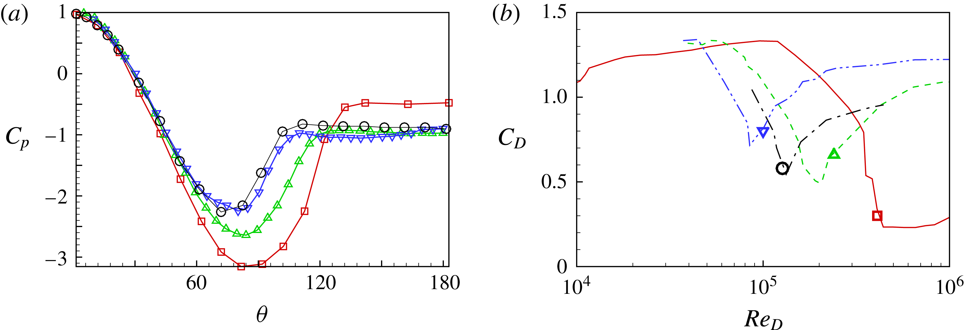
Figure 11. Comparison of experimental
 $C_{p}$
in the supercritical regime: (a) distribution of
$C_{p}$
in the supercritical regime: (a) distribution of
 $C_{p}$
for four cases; (b) location of four cases in a
$C_{p}$
for four cases; (b) location of four cases in a
 $C_{D}$
plot. ▫ (——),
$C_{D}$
plot. ▫ (——),
 $Re_{D}=4.1\times 10^{5}$
, smooth-cylinder flow
$Re_{D}=4.1\times 10^{5}$
, smooth-cylinder flow
 $\unicode[STIX]{x1D716}/D=0$
(Güven et al.
Reference Güven, Farell and Patel1980); ▵ (– – – –),
$\unicode[STIX]{x1D716}/D=0$
(Güven et al.
Reference Güven, Farell and Patel1980); ▵ (– – – –),
 $Re_{D}=2.4\times 10^{5}$
,
$Re_{D}=2.4\times 10^{5}$
,
 $\unicode[STIX]{x1D716}/D=0.7\times 10^{-3}$
(Achenbach Reference Achenbach1971); ○, (— ⋅ —)
$\unicode[STIX]{x1D716}/D=0.7\times 10^{-3}$
(Achenbach Reference Achenbach1971); ○, (— ⋅ —)
 $Re_{D}=1.27\times 10^{5}$
,
$Re_{D}=1.27\times 10^{5}$
,
 $\unicode[STIX]{x1D716}/D=1.6\times 10^{-3}$
(Güven et al.
Reference Güven, Farell and Patel1980); ▿ (— ⋅ ⋅ —),
$\unicode[STIX]{x1D716}/D=1.6\times 10^{-3}$
(Güven et al.
Reference Güven, Farell and Patel1980); ▿ (— ⋅ ⋅ —),
 $Re_{D}=10^{5}$
,
$Re_{D}=10^{5}$
,
 $\unicode[STIX]{x1D716}/D=2.9\times 10^{-3}$
(Achenbach Reference Achenbach1971).
$\unicode[STIX]{x1D716}/D=2.9\times 10^{-3}$
(Achenbach Reference Achenbach1971).

Figure 12. Comparison of
 $C_{p}$
between LES data and rough-wall experiment: ——, LES at
$C_{p}$
between LES data and rough-wall experiment: ——, LES at
 $Re_{D}=5\times 10^{4}$
,
$Re_{D}=5\times 10^{4}$
,
 $k=32$
and
$k=32$
and
 $\unicode[STIX]{x1D716}/D=1/32$
. For legend, see figure 11.
$\unicode[STIX]{x1D716}/D=1/32$
. For legend, see figure 11.
In figure 11, the four corresponding
 $C_{p}$
distributions are plotted. For the smooth-cylinder case, the minimal value can approach
$C_{p}$
distributions are plotted. For the smooth-cylinder case, the minimal value can approach
 $C_{p}=-3$
, while for the experiments with three-dimensional geometry perturbations, the minimal value increases substantially. The two higher
$C_{p}=-3$
, while for the experiments with three-dimensional geometry perturbations, the minimal value increases substantially. The two higher
 $\unicode[STIX]{x1D716}/D$
cases show similar
$\unicode[STIX]{x1D716}/D$
cases show similar
 $C_{p}$
distributions. These same two
$C_{p}$
distributions. These same two
 $C_{p}$
distributions are also shown in figure 12 in comparison with results from the present LES at
$C_{p}$
distributions are also shown in figure 12 in comparison with results from the present LES at
 $Re_{D}=5\times 10^{4}$
. While the LES are for two-dimensional grooves with
$Re_{D}=5\times 10^{4}$
. While the LES are for two-dimensional grooves with
 $\unicode[STIX]{x1D716}/D=1/32$
, the general behaviour of the
$\unicode[STIX]{x1D716}/D=1/32$
, the general behaviour of the
 $C_{p}$
distributions is similar, including the minimal value of
$C_{p}$
distributions is similar, including the minimal value of
 $C_{p}$
, the increasing tendency from the minimal value to the plateau value and also the plateau value.
$C_{p}$
, the increasing tendency from the minimal value to the plateau value and also the plateau value.

Figure 13. Comparison of
 $C_{p}$
between LES data and grooved-wall experiment: ——, LES at
$C_{p}$
between LES data and grooved-wall experiment: ——, LES at
 $Re_{D}=5\times 10^{4}$
,
$Re_{D}=5\times 10^{4}$
,
 $k=32$
and
$k=32$
and
 $\unicode[STIX]{x1D716}/D=1/32$
. Experimental data at
$\unicode[STIX]{x1D716}/D=1/32$
. Experimental data at
 $Re_{D}=10^{5}$
by Yamagishi & Oki (Reference Yamagishi and Oki2004): ○, arc groove; ▵, triangle groove.
$Re_{D}=10^{5}$
by Yamagishi & Oki (Reference Yamagishi and Oki2004): ○, arc groove; ▵, triangle groove.
We can also compare the present LES with experimental results by Yamagishi & Oki (Reference Yamagishi and Oki2004) for flow over a cylinder with two-dimensional grooves, with two different shapes: triangle- or arc-shaped grooves. Experimental data at
 $Re_{D}=10^{5}$
are compared with present LES calculations at
$Re_{D}=10^{5}$
are compared with present LES calculations at
 $Re_{D}=5\times 10^{4}$
in figure 13. This shows good agreement for the front part of the cylinder and for the plateau region. For the range
$Re_{D}=5\times 10^{4}$
in figure 13. This shows good agreement for the front part of the cylinder and for the plateau region. For the range
 $50<\unicode[STIX]{x1D703}<90^{\circ }$
, both experiments and LES show small structures in each groove and their peaks match each other. We note that there are differences between experiment and LES in
$50<\unicode[STIX]{x1D703}<90^{\circ }$
, both experiments and LES show small structures in each groove and their peaks match each other. We note that there are differences between experiment and LES in
 $90<\unicode[STIX]{x1D703}<120^{\circ }$
. This agrees with our physical interpretation that the present LES at
$90<\unicode[STIX]{x1D703}<120^{\circ }$
. This agrees with our physical interpretation that the present LES at
 $Re_{D}=5\times 10^{4}$
reaches the start of the transcritical regime while experimental results at
$Re_{D}=5\times 10^{4}$
reaches the start of the transcritical regime while experimental results at
 $Re_{D}=10^{5}$
lie well within the transcritical regime.
$Re_{D}=10^{5}$
lie well within the transcritical regime.

Figure 14. Comparison of drag coefficient
 $C_{D}$
between LES and experiment: ▪, LES with
$C_{D}$
between LES and experiment: ▪, LES with
 $\unicode[STIX]{x1D716}/D=1/32$
, ▾, LES with
$\unicode[STIX]{x1D716}/D=1/32$
, ▾, LES with
 $\unicode[STIX]{x1D716}/D=1/80$
. (a) Experiments of grooved cylinder by Yamagishi & Oki (Reference Yamagishi and Oki2004): ○, arc groove; ▵, triangle groove. (b) Experiments of non-smooth cylinder with 3-D geometric perturbation: ▵,
$\unicode[STIX]{x1D716}/D=1/80$
. (a) Experiments of grooved cylinder by Yamagishi & Oki (Reference Yamagishi and Oki2004): ○, arc groove; ▵, triangle groove. (b) Experiments of non-smooth cylinder with 3-D geometric perturbation: ▵,
 $\unicode[STIX]{x1D716}/D=0.03$
from experiment with R3DP by Achenbach & Heinecke (Reference Achenbach and Heinecke1981); ○,
$\unicode[STIX]{x1D716}/D=0.03$
from experiment with R3DP by Achenbach & Heinecke (Reference Achenbach and Heinecke1981); ○,
 $\unicode[STIX]{x1D716}/D=0.02$
from experiment with embedded glass perturbations by Fage & Warsap (Reference Fage and Warsap1929); – – – –, smooth-wall experiments by Schewe (Reference Schewe1983) (for comparison).
$\unicode[STIX]{x1D716}/D=0.02$
from experiment with embedded glass perturbations by Fage & Warsap (Reference Fage and Warsap1929); – – – –, smooth-wall experiments by Schewe (Reference Schewe1983) (for comparison).
4.2 The drag coefficient
$C_{D}$

The drag coefficient
 $C_{D}$
, which is a combination of integrated pressure and viscous contributions, is shown in figure 14 where LES results are compared with two sets of experimental data. Figure 14(a) shows the two-dimensional groove experiments by Yamagishi & Oki (Reference Yamagishi and Oki2004). The present LES with
$C_{D}$
, which is a combination of integrated pressure and viscous contributions, is shown in figure 14 where LES results are compared with two sets of experimental data. Figure 14(a) shows the two-dimensional groove experiments by Yamagishi & Oki (Reference Yamagishi and Oki2004). The present LES with
 $k=32$
and
$k=32$
and
 $\unicode[STIX]{x1D716}/D=1/32$
, generally follows the experimental data for arc and triangle grooves even though for the latter,
$\unicode[STIX]{x1D716}/D=1/32$
, generally follows the experimental data for arc and triangle grooves even though for the latter,
 $\unicode[STIX]{x1D716}/D\approx 0.011$
. Also plotted is a third set of LES (table 4) with
$\unicode[STIX]{x1D716}/D\approx 0.011$
. Also plotted is a third set of LES (table 4) with
 $k=32$
and
$k=32$
and
 $\unicode[STIX]{x1D716}/D=1/80$
, which, at
$\unicode[STIX]{x1D716}/D=1/80$
, which, at
 $Re_{D}=5\times 10^{4}$
lies within the drag crisis, but does not reach the supercritical regime. Figure 14(b) compares
$Re_{D}=5\times 10^{4}$
lies within the drag crisis, but does not reach the supercritical regime. Figure 14(b) compares
 $C_{D}$
for the LES with experimental results for three-dimensional cylinder perturbations, including R3DP by Achenbach & Heinecke (Reference Achenbach and Heinecke1981) and glass perturbations by Fage & Warsap (Reference Fage and Warsap1929). Here LES and experiments have similar values of
$C_{D}$
for the LES with experimental results for three-dimensional cylinder perturbations, including R3DP by Achenbach & Heinecke (Reference Achenbach and Heinecke1981) and glass perturbations by Fage & Warsap (Reference Fage and Warsap1929). Here LES and experiments have similar values of
 $\unicode[STIX]{x1D716}/D$
. They show quite similar
$\unicode[STIX]{x1D716}/D$
. They show quite similar
 $C_{D}-Re_{D}$
behaviour despite the fact that the LES employs two-dimensional spanwise grooves.
$C_{D}-Re_{D}$
behaviour despite the fact that the LES employs two-dimensional spanwise grooves.
4.3 Mean-flow field
From the
 $C_{D}-Re_{D}$
plot, it is clear that for
$C_{D}-Re_{D}$
plot, it is clear that for
 $\unicode[STIX]{x1D716}/D=1/32$
, our LES of the flow at
$\unicode[STIX]{x1D716}/D=1/32$
, our LES of the flow at
 $Re_{D}=1\times 10^{4}$
is still within the subcritical regime, while the flow with
$Re_{D}=1\times 10^{4}$
is still within the subcritical regime, while the flow with
 $Re_{D}=2\times 10^{4}$
is in transition to the supercritical regime, and that
$Re_{D}=2\times 10^{4}$
is in transition to the supercritical regime, and that
 $Re_{D}=5\times 10^{4}$
reaches the beginning of the transcritical regime. To understand the role of grooves in the transition, we plot the streamlines of the mean-flow field, with focus on the separated region, as shown in figure 15.
$Re_{D}=5\times 10^{4}$
reaches the beginning of the transcritical regime. To understand the role of grooves in the transition, we plot the streamlines of the mean-flow field, with focus on the separated region, as shown in figure 15.

Figure 15. Local streamlines of mean velocity around the separation region: (a)
 $Re_{D}=3.9\times 10^{3}$
; (b)
$Re_{D}=3.9\times 10^{3}$
; (b)
 $Re_{D}=8\times 10^{3}$
; (c)
$Re_{D}=8\times 10^{3}$
; (c)
 $Re_{D}=1\times 10^{4}$
; (d)
$Re_{D}=1\times 10^{4}$
; (d)
 $Re_{D}=1.05\times 10^{4}$
; (e)
$Re_{D}=1.05\times 10^{4}$
; (e)
 $Re_{D}=2\times 10^{4}$
; (f)
$Re_{D}=2\times 10^{4}$
; (f)
 $Re_{D}=5\times 10^{4}$
.
$Re_{D}=5\times 10^{4}$
.
In figure 15(a), we show the streamlines for
 $Re_{D}=3.9\times 10^{3}$
, which, as described earlier, shows a primary separation at around
$Re_{D}=3.9\times 10^{3}$
, which, as described earlier, shows a primary separation at around
 $x=0$
and a secondary separation bubble which reattaches at about
$x=0$
and a secondary separation bubble which reattaches at about
 $x=0.2$
. Upstream of the secondary separation bubble, a small anti-clockwise bubble exists. When
$x=0.2$
. Upstream of the secondary separation bubble, a small anti-clockwise bubble exists. When
 $Re_{D}$
is increased to
$Re_{D}$
is increased to
 $8000$
, as shown in figure 15(b), no obvious change is observed except the growth of the anti-clockwise bubble. With further increase to
$8000$
, as shown in figure 15(b), no obvious change is observed except the growth of the anti-clockwise bubble. With further increase to
 $Re_{D}=10^{4}$
, another anti-clockwise bubble emerges under the separation point of the primary separation bubble, which is labelled as
$Re_{D}=10^{4}$
, another anti-clockwise bubble emerges under the separation point of the primary separation bubble, which is labelled as
 $P/A$
in figure 15(c). The development of anti-clockwise bubbles are signs that the secondary separation bubble, and in particular its mean-flow reattachment line, are moving upstream along the cylinder surface, as
$P/A$
in figure 15(c). The development of anti-clockwise bubbles are signs that the secondary separation bubble, and in particular its mean-flow reattachment line, are moving upstream along the cylinder surface, as
 $Re_{D}$
is increased.
$Re_{D}$
is increased.
A further small increase of
 $Re_{D}$
gives a notably different topology. In figure 15(d), we can see that the anti-clockwise bubble, which previously existed just upstream of the secondary separation bubble, is absorbed. The change results in a leapfrogging movement upstream of the reattachment point of the secondary separation bubble, which is now at around
$Re_{D}$
gives a notably different topology. In figure 15(d), we can see that the anti-clockwise bubble, which previously existed just upstream of the secondary separation bubble, is absorbed. The change results in a leapfrogging movement upstream of the reattachment point of the secondary separation bubble, which is now at around
 $x=0.1$
. This tendency is quite similar to observations from LES of smooth-walled cylinder flows (Cheng et al.
Reference Cheng, Pullin, Samtaney, Zhang and Gao2017), where the secondary separation bubble also moves upstream in the subcritical regime, as
$x=0.1$
. This tendency is quite similar to observations from LES of smooth-walled cylinder flows (Cheng et al.
Reference Cheng, Pullin, Samtaney, Zhang and Gao2017), where the secondary separation bubble also moves upstream in the subcritical regime, as
 $Re_{D}$
is increased.
$Re_{D}$
is increased.
When transition to supercritical flow occurs, the flow topology changes significantly. With further increase in
 $Re_{D}$
, as shown in figure 15(e) for
$Re_{D}$
, as shown in figure 15(e) for
 $Re_{D}=2\times 10^{4}$
, the first anti-clockwise trapped bubble still moves forward but now combines with a clockwise trapped bubble (C/A) prior to the primary separation line which labelled as
$Re_{D}=2\times 10^{4}$
, the first anti-clockwise trapped bubble still moves forward but now combines with a clockwise trapped bubble (C/A) prior to the primary separation line which labelled as
 $P/A$
. At this transition
$P/A$
. At this transition
 $Re_{D}$
no secondary separation bubble exists. At the same time, all bubbles in the leeward flow are locally trapped with mean-flow anti-clockwise motion (A).
$Re_{D}$
no secondary separation bubble exists. At the same time, all bubbles in the leeward flow are locally trapped with mean-flow anti-clockwise motion (A).
This feature of the flow field at subcritical to supercritical transition is essentially similar to the same phenomena in the smooth-cylinder transition flow. For the latter case Cheng et al. (Reference Cheng, Pullin, Samtaney, Zhang and Gao2017) concluded that the change in the mean-flow secondary separation bubble, from anti-clockwise and located within the large-scale separated flow, to a prior, clockwise, separation bubble, is an important mechanism that stimulates the drag crisis. In the present grooved-cylinder flow, owing to strong trapping effects in each groove, the secondary separation bubble gradually shrinks and separates into several anti-clockwise trapped bubbles. This phenomenon cannot occur in the smooth-cylinder flow.

Figure 16. History of the lift coefficient
 $C_{L}$
for different
$C_{L}$
for different
 $Re_{D}$
: ——,
$Re_{D}$
: ——,
 $3.9\times 10^{3}$
; – – – –,
$3.9\times 10^{3}$
; – – – –,
 $2\times 10^{4}$
; — ⋅ —,
$2\times 10^{4}$
; — ⋅ —,
 $5\times 10^{4}$
.
$5\times 10^{4}$
.
With further increase in
 $Re_{D}$
to
$Re_{D}$
to
 $Re_{D}=5\times 10^{4}$
, as shown in figure 15(c), the
$Re_{D}=5\times 10^{4}$
, as shown in figure 15(c), the
 $C/A$
structure disappears, and inside all upwind grooves are trapped clockwise bubbles, save possibly for a tiny bubble in the second groove from the left in the figure. For the leeward flow, the
$C/A$
structure disappears, and inside all upwind grooves are trapped clockwise bubbles, save possibly for a tiny bubble in the second groove from the left in the figure. For the leeward flow, the
 $P/A$
configuration also disappears and all trapped bubbles flow in an anti-clockwise direction. This perhaps can be interpreted as a signature of the flow having reached the transcritical regime. The analogous criterion for transcritical flow in the smooth-cylinder case is the disappearance of the prior separation bubble (Roshko Reference Roshko1961).
$P/A$
configuration also disappears and all trapped bubbles flow in an anti-clockwise direction. This perhaps can be interpreted as a signature of the flow having reached the transcritical regime. The analogous criterion for transcritical flow in the smooth-cylinder case is the disappearance of the prior separation bubble (Roshko Reference Roshko1961).
5 Unsteady and instantaneous flow features
In previous sections, mean results of the LES have been discussed together with comparison with available experimental data. Other important flow properties can be revealed from the tracking of unsteady flow features, for example, the Strouhal number
 $St\equiv f\,D/U_{\infty }$
, where
$St\equiv f\,D/U_{\infty }$
, where
 $f$
is the shedding frequency. We now consider unsteady and three-dimensional flow dynamics via investigation of instantaneous variables, such as the one-dimensional drag and lift coefficients, two-dimensional vector skin-friction lines and three-dimensional isoline plots of near-wall flow structures.
$f$
is the shedding frequency. We now consider unsteady and three-dimensional flow dynamics via investigation of instantaneous variables, such as the one-dimensional drag and lift coefficients, two-dimensional vector skin-friction lines and three-dimensional isoline plots of near-wall flow structures.
5.1 The instantaneous lift and drag coefficients
$C_{L}(t)$
and
$C_{D}(t)$


The history of the lift coefficient
 $C_{L}(t)$
can be revealing in understanding the phenomenon of vortex shedding. Schewe (Reference Schewe1983) discusses the spectral analysis of
$C_{L}(t)$
can be revealing in understanding the phenomenon of vortex shedding. Schewe (Reference Schewe1983) discusses the spectral analysis of
 $C_{L}(t)$
from experimental data, providing evidence for a dominant shedding frequency around
$C_{L}(t)$
from experimental data, providing evidence for a dominant shedding frequency around
 $St=0.2$
in the subcritical regime,
$St=0.2$
in the subcritical regime,
 $St=0.47$
in the supercritical regime, transition to a sub-region of transcritical regime where no dominant frequency can be found and a wide spectral content is observed, and then finally to the full transcritical regime where a dominant frequency of about
$St=0.47$
in the supercritical regime, transition to a sub-region of transcritical regime where no dominant frequency can be found and a wide spectral content is observed, and then finally to the full transcritical regime where a dominant frequency of about
 $St=0.27$
emerges. The no-dominant-frequency region was quite ambiguous before the classical experiments by Roshko (Reference Roshko1961). For a non-smooth cylinder, the R3DP experiments of Achenbach & Heinecke (Reference Achenbach and Heinecke1981) show no evidence of the existence of a no-dominant-frequency sub-region of the transcritical regime.
$St=0.27$
emerges. The no-dominant-frequency region was quite ambiguous before the classical experiments by Roshko (Reference Roshko1961). For a non-smooth cylinder, the R3DP experiments of Achenbach & Heinecke (Reference Achenbach and Heinecke1981) show no evidence of the existence of a no-dominant-frequency sub-region of the transcritical regime.
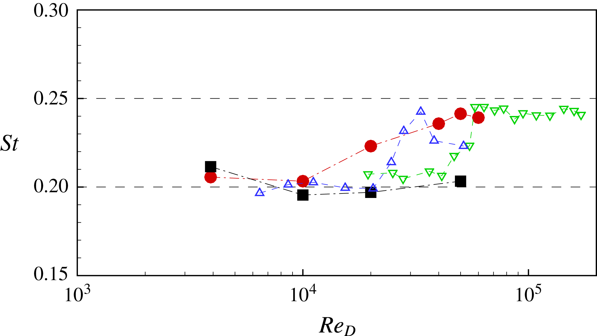
Figure 17. Strouhal number
 $St$
: comparison of LES (●,
$St$
: comparison of LES (●,
 $\unicode[STIX]{x1D716}/D=1/32$
; ▪,
$\unicode[STIX]{x1D716}/D=1/32$
; ▪,
 $\unicode[STIX]{x1D716}/D=1/80$
) with experiment of non-smooth cylinder with R3DP by Achenbach & Heinecke (Reference Achenbach and Heinecke1981) (▵,
$\unicode[STIX]{x1D716}/D=1/80$
) with experiment of non-smooth cylinder with R3DP by Achenbach & Heinecke (Reference Achenbach and Heinecke1981) (▵,
 $\unicode[STIX]{x1D716}/D=0.03$
; ▿,
$\unicode[STIX]{x1D716}/D=0.03$
; ▿,
 $\unicode[STIX]{x1D716}/D=0.006$
).
$\unicode[STIX]{x1D716}/D=0.006$
).

Figure 18. History of the drag coefficient
 $C_{D}$
: (a)
$C_{D}$
: (a)
 $Re_{D}=3.9\times 10^{3}$
; (b)
$Re_{D}=3.9\times 10^{3}$
; (b)
 $Re_{D}=5\times 10^{4}$
.
$Re_{D}=5\times 10^{4}$
.
Three
 $C_{L}(t)$
time series from the present LES are shown in figure 16, including
$C_{L}(t)$
time series from the present LES are shown in figure 16, including
 $Re_{D}=3.9\times 10^{3}$
,
$Re_{D}=3.9\times 10^{3}$
,
 $Re_{D}=2\times 10^{4}$
and
$Re_{D}=2\times 10^{4}$
and
 $Re_{D}=5\times 10^{4}$
. While
$Re_{D}=5\times 10^{4}$
. While
 $f$
and the magnitude of the
$f$
and the magnitude of the
 $C_{L}(t)$
oscillations vary with
$C_{L}(t)$
oscillations vary with
 $Re_{D}$
, the general trend of the
$Re_{D}$
, the general trend of the
 $C_{L}(t)$
variation is similar for all cases. The Strouhal number
$C_{L}(t)$
variation is similar for all cases. The Strouhal number
 $St$
versus
$St$
versus
 $Re_{D}$
is shown in figure 17 in comparison with the rough-cylinder experiments of Achenbach & Heinecke (Reference Achenbach and Heinecke1981). All results generally show a smooth transition from the subcritical regime where
$Re_{D}$
is shown in figure 17 in comparison with the rough-cylinder experiments of Achenbach & Heinecke (Reference Achenbach and Heinecke1981). All results generally show a smooth transition from the subcritical regime where
 $St\approx 0.2$
to the final transcritical regime where
$St\approx 0.2$
to the final transcritical regime where
 $St\approx 0.25$
.
$St\approx 0.25$
.
Some insight into the behaviour of
 $C_{L}(t)$
in different regimes can be inferred by observation of the drag coefficient
$C_{L}(t)$
in different regimes can be inferred by observation of the drag coefficient
 $C_{D}(t)$
. In the experiments by Schewe (Reference Schewe1983), for near-critical-state flow, a secondary frequency can be observed in
$C_{D}(t)$
. In the experiments by Schewe (Reference Schewe1983), for near-critical-state flow, a secondary frequency can be observed in
 $C_{D}(t)$
which interacts with the primary shedding frequency. For the present LES of the grooved-cylinder flow, a secondary frequency can also be identified at high
$C_{D}(t)$
which interacts with the primary shedding frequency. For the present LES of the grooved-cylinder flow, a secondary frequency can also be identified at high
 $Re_{D}$
, as shown in figure 18. It can be seen that
$Re_{D}$
, as shown in figure 18. It can be seen that
 $C_{D}(t)$
at high
$C_{D}(t)$
at high
 $Re_{D}$
exhibits a high frequency oscillation which is quite distinct from the low frequency that dominates the vortex shedding. This high frequency is generally found to be at approximately
$Re_{D}$
exhibits a high frequency oscillation which is quite distinct from the low frequency that dominates the vortex shedding. This high frequency is generally found to be at approximately
 $16$
times
$16$
times
 $St$
, which indicates that it is mainly produced by the geometrical perturbation of the grooved cylinder. In contrast, for the smooth cylinder flow the presence of wall turbulence possibly generates higher frequency oscillations.
$St$
, which indicates that it is mainly produced by the geometrical perturbation of the grooved cylinder. In contrast, for the smooth cylinder flow the presence of wall turbulence possibly generates higher frequency oscillations.
5.2 Surface skin-friction lines
The mean flow exists as a two-dimensional projection onto a spanwise normal plane. In order to consider three-dimensional flow effects, we first plot the instantaneous limiting streamlines at the cylinder wall that correspond to the surface skin-friction vector field, or skin-friction lines. These are generally unsteady in that the surface vector field changes as a function of time through shedding cycles. Presently we show typical instantaneous images at an arbitrary time instant. Since the grooved cylinder has a mildly complex surface shape, the present plots will simply project the real skin-friction vectors onto the unperturbed cylinder surface, with
 $(\unicode[STIX]{x1D703},y)$
as projected surface coordinates.
$(\unicode[STIX]{x1D703},y)$
as projected surface coordinates.

Figure 19. Instantaneous skin-friction lines of the subcritical regime: (a)
 $Re_{D}=3.9\times 10^{3}$
; (b)
$Re_{D}=3.9\times 10^{3}$
; (b)
 $Re_{D}=1.75\times 10^{4}$
.
$Re_{D}=1.75\times 10^{4}$
.
In figure 19, two portraits of instantaneous surface skin-friction lines in the subcritical regime are shown. The top of each skin-friction line plot indicates both peaks and valleys of grooves and also the corresponding mean-flow groove characteristic as previously denoted by
 $C$
,
$C$
,
 $A$
,
$A$
,
 $P$
and
$P$
and
 $S$
. In figure 19(a) at
$S$
. In figure 19(a) at
 $Re_{D}=3.9\times 10^{3}$
, the skin-friction lines upstream of the primary separation region are generally straight lines, which indicates that there is no near-surface spanwise motion. In figure 19(b) for
$Re_{D}=3.9\times 10^{3}$
, the skin-friction lines upstream of the primary separation region are generally straight lines, which indicates that there is no near-surface spanwise motion. In figure 19(b) for
 $Re_{D}=1.75\times 10^{4}$
, a two-dimensional surface structure is clearly observed which occupies a scale
$Re_{D}=1.75\times 10^{4}$
, a two-dimensional surface structure is clearly observed which occupies a scale
 $\unicode[STIX]{x03C0}/16$
in size in the spanwise direction. This is almost the same as the half-wavelength of the groove in the circumferential direction. It is notable that for both
$\unicode[STIX]{x03C0}/16$
in size in the spanwise direction. This is almost the same as the half-wavelength of the groove in the circumferential direction. It is notable that for both
 $Re_{D}$
, skin-friction lines downstream of the primary separation show substantial spanwise motion indicating a fully three-dimensional flow above.
$Re_{D}$
, skin-friction lines downstream of the primary separation show substantial spanwise motion indicating a fully three-dimensional flow above.

Figure 20.
 $Re_{D}=2\times 10^{4}$
: (a) skin-friction lines; (b) vortex lines.
$Re_{D}=2\times 10^{4}$
: (a) skin-friction lines; (b) vortex lines.
In figure 20(a), a skin-friction portrait for
 $Re_{D}=2\times 10^{4}$
is shown. This clearly shows two-dimensional surface structure, and thus three-dimensional off-wall motion, even on the very front part of the grooved cylinder. In grooves upstream of the primary separation, although the mean flow exhibits a clockwise trapped bubble, the instantaneous skin-friction lines show irregular two-dimensional near-wall flow that destroys the symmetry in the spanwise direction for the two-dimensional mean-flow structures. In figure 20(b), the surface vortex direction field at the same
$Re_{D}=2\times 10^{4}$
is shown. This clearly shows two-dimensional surface structure, and thus three-dimensional off-wall motion, even on the very front part of the grooved cylinder. In grooves upstream of the primary separation, although the mean flow exhibits a clockwise trapped bubble, the instantaneous skin-friction lines show irregular two-dimensional near-wall flow that destroys the symmetry in the spanwise direction for the two-dimensional mean-flow structures. In figure 20(b), the surface vortex direction field at the same
 $Re_{D}$
is shown. The surface vortex lines are everywhere orthogonal to the skin-friction lines. In both images in figure 20, the skin-friction and the surface vortex lines exhibit a nearly spanwise-periodic, cell-like structure for the first two grooves shown. Further downstream this breaks down into an irregular spanwise field. Still further downstream in the primary separation bubble region, vortex lines are almost streamwise straight lines. We show skin-friction lines at
$Re_{D}$
is shown. The surface vortex lines are everywhere orthogonal to the skin-friction lines. In both images in figure 20, the skin-friction and the surface vortex lines exhibit a nearly spanwise-periodic, cell-like structure for the first two grooves shown. Further downstream this breaks down into an irregular spanwise field. Still further downstream in the primary separation bubble region, vortex lines are almost streamwise straight lines. We show skin-friction lines at
 $Re_{D}=5\times 10^{4}$
in figure 21. In this case, the breakdown of the two-dimensional surface structure takes place even upstream.
$Re_{D}=5\times 10^{4}$
in figure 21. In this case, the breakdown of the two-dimensional surface structure takes place even upstream.

Figure 21. Instantaneous skin-friction lines at
 $Re_{D}=5\times 10^{4}$
.
$Re_{D}=5\times 10^{4}$
.
5.3 Plots of Q-criterion
In order to visualize instantaneous flow structure away from the wall, we consider the second invariant of the velocity gradient tensor, which is typically defined as
 $Q$
(see Chakraborty, Balachandar & Adrian Reference Chakraborty, Balachandar and Adrian2005)
$Q$
(see Chakraborty, Balachandar & Adrian Reference Chakraborty, Balachandar and Adrian2005)
 $$\begin{eqnarray}Q={\textstyle \frac{1}{2}}\,(\Vert \unicode[STIX]{x1D734}\Vert ^{2}-\Vert \boldsymbol{S}\Vert ^{2}),\end{eqnarray}$$
where
 $\unicode[STIX]{x1D64E}=1/2\,(\unicode[STIX]{x1D735}\boldsymbol{u}+(\unicode[STIX]{x1D735}\boldsymbol{u})^{\text{T}})$
,
$\unicode[STIX]{x1D64E}=1/2\,(\unicode[STIX]{x1D735}\boldsymbol{u}+(\unicode[STIX]{x1D735}\boldsymbol{u})^{\text{T}})$
,
 $\unicode[STIX]{x1D734}=1/2\,(\unicode[STIX]{x1D735}\boldsymbol{u}-(\unicode[STIX]{x1D735}\boldsymbol{u})^{\text{T}})$
are the rate-of-strain and the rotation tensors respectively. In figure 22 we show instantaneous iso-surfaces of
$\unicode[STIX]{x1D734}=1/2\,(\unicode[STIX]{x1D735}\boldsymbol{u}-(\unicode[STIX]{x1D735}\boldsymbol{u})^{\text{T}})$
are the rate-of-strain and the rotation tensors respectively. In figure 22 we show instantaneous iso-surfaces of
 $Q=1$
coloured by
$Q=1$
coloured by
 $u_{x}$
. The four panels use similar
$u_{x}$
. The four panels use similar
 $Re_{D}$
values as for the skin-friction plots of figures 20–26. For the two lower
$Re_{D}$
values as for the skin-friction plots of figures 20–26. For the two lower
 $Re_{D}$
at
$Re_{D}$
at
 $3.9\times 10^{3}$
and
$3.9\times 10^{3}$
and
 $1.75\times 10^{4}$
, a relatively large near-cylinder domain is shown to illustrate how the flow develops from the boundary-layer flow into the wake. At
$1.75\times 10^{4}$
, a relatively large near-cylinder domain is shown to illustrate how the flow develops from the boundary-layer flow into the wake. At
 $3.9\times 10^{3}$
in figure 22(a), the front part of the cylinder shows no variance in the spanwise direction. Only streamwise perturbations, which are induced by the grooves, can be seen. For flow at
$3.9\times 10^{3}$
in figure 22(a), the front part of the cylinder shows no variance in the spanwise direction. Only streamwise perturbations, which are induced by the grooves, can be seen. For flow at
 $1.74\times 10^{4}$
, structure development in the spanwise direction is found to move upstream from the wake and approach the front of the cylinder. In this case, the breakdown of the spanwise uniformity generates some regular structures, which then further interact with the streamwise perturbations and roll finally into the near-wake flow.
$1.74\times 10^{4}$
, structure development in the spanwise direction is found to move upstream from the wake and approach the front of the cylinder. In this case, the breakdown of the spanwise uniformity generates some regular structures, which then further interact with the streamwise perturbations and roll finally into the near-wake flow.

Figure 22. Instantaneous flow on the front part of the cylinder.
 $Q=1$
and coloured by
$Q=1$
and coloured by
 $u_{x}$
. (a)
$u_{x}$
. (a)
 $Re_{D}=3.9\times 10^{3}$
; (b)
$Re_{D}=3.9\times 10^{3}$
; (b)
 $Re_{D}=1.75\times 10^{4}$
; (c)
$Re_{D}=1.75\times 10^{4}$
; (c)
 $Re_{D}=2\times 10^{4}$
; (d)
$Re_{D}=2\times 10^{4}$
; (d)
 $Re_{D}=5\times 10^{4}$
.
$Re_{D}=5\times 10^{4}$
.

Figure 23. Instantaneous wake flow.
 $Q=1$
and coloured by
$Q=1$
and coloured by
 $u_{x}$
. (a)
$u_{x}$
. (a)
 $Re_{D}=3.9\times 10^{3}$
; (b)
$Re_{D}=3.9\times 10^{3}$
; (b)
 $Re_{D}=1\times 10^{4}$
; (c)
$Re_{D}=1\times 10^{4}$
; (c)
 $Re_{D}=2\times 10^{4}$
; (d)
$Re_{D}=2\times 10^{4}$
; (d)
 $Re_{D}=5\times 10^{4}$
.
$Re_{D}=5\times 10^{4}$
.
In figure 22(c) at
 $Re_{D}=2\times 10^{4}$
, spanwise perturbations are formed at smaller
$Re_{D}=2\times 10^{4}$
, spanwise perturbations are formed at smaller
 $\unicode[STIX]{x1D703}$
than the smaller
$\unicode[STIX]{x1D703}$
than the smaller
 $Re_{D}$
flows. With further increase of
$Re_{D}$
flows. With further increase of
 $Re_{D}$
to
$Re_{D}$
to
 $5\times 10^{4}$
, we can observe in figure 22(d) that spanwise regular structures are not apparent and the flow quickly breaks into irregular small scales. As
$5\times 10^{4}$
, we can observe in figure 22(d) that spanwise regular structures are not apparent and the flow quickly breaks into irregular small scales. As
 $Re_{D}$
increases in figure 22, the reduction in the scale of the visible eddies is clear. This is believed to be a genuine
$Re_{D}$
increases in figure 22, the reduction in the scale of the visible eddies is clear. This is believed to be a genuine
 $Re_{D}$
effect and not an artefact of either grid resolution or the visualization scheme. It is interesting to observe that, in the breakdown process of spanwise structures for
$Re_{D}$
effect and not an artefact of either grid resolution or the visualization scheme. It is interesting to observe that, in the breakdown process of spanwise structures for
 $Re_{D}=2\times 10^{4}$
, some
$Re_{D}=2\times 10^{4}$
, some
 $\unicode[STIX]{x1D6EC}$
-shaped vortices emerge, which are similar to the vortices observed in the flat-plate turbulent transition by Sayadi, Hamman & Moin (Reference Sayadi, Hamman and Moin2013).
$\unicode[STIX]{x1D6EC}$
-shaped vortices emerge, which are similar to the vortices observed in the flat-plate turbulent transition by Sayadi, Hamman & Moin (Reference Sayadi, Hamman and Moin2013).
While the present work is not a study of the wake dynamics, we nonetheless demonstrate that the present LES does indeed produce a healthy wake structure for the present flow. Full side views using the Q-parameter of streamwise extent up to
 $13D$
are shown in figure 23 for several different
$13D$
are shown in figure 23 for several different
 $Re_{D}$
. It is clear that the present LES and associated mesh structure provides a physically convincing wake flow. A detailed study of the wake flow is beyond the scope of the present work, which is focused on surface and near-surface properties of the flow, and so is not discussed further.
$Re_{D}$
. It is clear that the present LES and associated mesh structure provides a physically convincing wake flow. A detailed study of the wake flow is beyond the scope of the present work, which is focused on surface and near-surface properties of the flow, and so is not discussed further.
6 Discussion
6.1 Mean-flow separation angle

Figure 24. Separation angle of the primary separation
 $\unicode[STIX]{x1D703}_{ps}$
: ▫, experiment by Son & Hanratty (Reference Son and Hanratty1969); △, experiment by Achenbach (Reference Achenbach1968); ●, present LES,
$\unicode[STIX]{x1D703}_{ps}$
: ▫, experiment by Son & Hanratty (Reference Son and Hanratty1969); △, experiment by Achenbach (Reference Achenbach1968); ●, present LES,
 $\unicode[STIX]{x1D716}/D=1/32$
and
$\unicode[STIX]{x1D716}/D=1/32$
and
 $k=32$
.
$k=32$
.
From the previous discussion, a natural question arises concerning the transitions between the subcritical, supercritical and transcritical regimes. In the smooth-cylinder flow, we can consider the structure and location of the secondary/prior separation bubble as a signature of transition between regimes. In the subcritical regime, a secondary separation bubble exists inside the primary mean-flow recirculation bubble. During transition to the supercritical regime, the mean-flow secondary separation bubble disappears followed, as
 $Re_{D}$
increases, by the creation of a prior separation bubble initially just upstream of the primary separation line. At higher
$Re_{D}$
increases, by the creation of a prior separation bubble initially just upstream of the primary separation line. At higher
 $Re_{D}$
, as the flow transitions to a transcritical state, the prior separation bubble itself vanishes and only primary mean-flow separation exists within the whole flow field (Cheng et al.
Reference Cheng, Pullin, Samtaney, Zhang and Gao2017). For subcritical flow, turbulent transition lies inside the wake flow and moves onto the highly sheared subregion that lies between the primary mean-flow separation line and the reattaching secondary bubble. For supercritical flows, the local Reynolds number is sufficiently large that transition to turbulence takes place on the upper surface of the (now) prior separation bubble while for transcritical flow, turbulent transition takes place directly within the boundary layer on the surface of the cylinder. For the subcritical regime with
$Re_{D}$
, as the flow transitions to a transcritical state, the prior separation bubble itself vanishes and only primary mean-flow separation exists within the whole flow field (Cheng et al.
Reference Cheng, Pullin, Samtaney, Zhang and Gao2017). For subcritical flow, turbulent transition lies inside the wake flow and moves onto the highly sheared subregion that lies between the primary mean-flow separation line and the reattaching secondary bubble. For supercritical flows, the local Reynolds number is sufficiently large that transition to turbulence takes place on the upper surface of the (now) prior separation bubble while for transcritical flow, turbulent transition takes place directly within the boundary layer on the surface of the cylinder. For the subcritical regime with
 $Re_{D}>10^{4}$
,
$Re_{D}>10^{4}$
,
 $C_{D}$
is nearly constant at approximately
$C_{D}$
is nearly constant at approximately
 $C_{D}=1.25$
. After a sudden drop, the drag coefficient decreases to approximately
$C_{D}=1.25$
. After a sudden drop, the drag coefficient decreases to approximately
 $C_{D}=0.3$
and remains at this value for a large range of
$C_{D}=0.3$
and remains at this value for a large range of
 $Re_{D}$
. This is recognized as the supercritical regime. In the transcritical regime,
$Re_{D}$
. This is recognized as the supercritical regime. In the transcritical regime,
 $C_{D}$
grows again and reaches a nearly constant value
$C_{D}$
grows again and reaches a nearly constant value
 $C_{D}\approx 0.7$
(Roshko Reference Roshko1961).
$C_{D}\approx 0.7$
(Roshko Reference Roshko1961).
The total drag around cylinder is the sum of the pressure drag (or form drag) and skin-friction drag. The form drag is mainly controlled by the position of the mean-flow primary separation angle
 $\unicode[STIX]{x1D703}_{ps}$
. In general, larger values of
$\unicode[STIX]{x1D703}_{ps}$
. In general, larger values of
 $\unicode[STIX]{x1D703}_{ps}$
indicate a smaller leeward region of base pressure and therefore smaller total drag. Within the supercritical regime in the smooth-cylinder flow, laminar–turbulent transition takes place on a prior separation bubble. The reattached turbulent flow results in an energized turbulent boundary layer that can resist an adverse pressure gradient more effectively than a laminar boundary layer. This in turn delays mean-flow separation with the result that the primary mean-flow separation point can be up to
$\unicode[STIX]{x1D703}_{ps}$
indicate a smaller leeward region of base pressure and therefore smaller total drag. Within the supercritical regime in the smooth-cylinder flow, laminar–turbulent transition takes place on a prior separation bubble. The reattached turbulent flow results in an energized turbulent boundary layer that can resist an adverse pressure gradient more effectively than a laminar boundary layer. This in turn delays mean-flow separation with the result that the primary mean-flow separation point can be up to
 $\unicode[STIX]{x1D703}_{ps}=140^{\circ }$
, corresponding to a low drag coefficient
$\unicode[STIX]{x1D703}_{ps}=140^{\circ }$
, corresponding to a low drag coefficient
 $C_{D}\approx 0.3$
. Experimental measurements of
$C_{D}\approx 0.3$
. Experimental measurements of
 $\unicode[STIX]{x1D703}_{ps}$
versus
$\unicode[STIX]{x1D703}_{ps}$
versus
 $Re_{D}$
(Son & Hanratty Reference Son and Hanratty1969) for the smooth-wall cylinder flow are shown in figure 24 where the rapid increase through the drag crisis is clearly evident.
$Re_{D}$
(Son & Hanratty Reference Son and Hanratty1969) for the smooth-wall cylinder flow are shown in figure 24 where the rapid increase through the drag crisis is clearly evident.
Also shown in figure 24 are values of
 $(\unicode[STIX]{x1D703}_{ps},Re_{D})$
for our LES of the grooved-cylinder flow with fixed
$(\unicode[STIX]{x1D703}_{ps},Re_{D})$
for our LES of the grooved-cylinder flow with fixed
 $\unicode[STIX]{x1D716}/D=1/32$
. These show a much smaller change through the drag crisis and into the beginning of the transcritical regime in comparison with the smooth-wall flow. Although the present LES penetrates only the lower
$\unicode[STIX]{x1D716}/D=1/32$
. These show a much smaller change through the drag crisis and into the beginning of the transcritical regime in comparison with the smooth-wall flow. Although the present LES penetrates only the lower
 $Re_{D}$
range of the transcritical regime for the grooved-cylinder flow, figure 3 of Achenbach & Heinecke (Reference Achenbach and Heinecke1981) indicates that for several rough-surface cylinder flows
$Re_{D}$
range of the transcritical regime for the grooved-cylinder flow, figure 3 of Achenbach & Heinecke (Reference Achenbach and Heinecke1981) indicates that for several rough-surface cylinder flows
 $C_{D}$
, and hence also
$C_{D}$
, and hence also
 $\unicode[STIX]{x1D703}_{ps}$
, remains sensibly constant far into the transcritical regime. This suggests that, for the non-smooth surface case, especially for large grooves or three-dimensional periodic surface shapes, laminar–turbulent flow transition is not the underlying mechanism that stimulates the drag crisis at much lower
$\unicode[STIX]{x1D703}_{ps}$
, remains sensibly constant far into the transcritical regime. This suggests that, for the non-smooth surface case, especially for large grooves or three-dimensional periodic surface shapes, laminar–turbulent flow transition is not the underlying mechanism that stimulates the drag crisis at much lower
 $Re_{D}$
than for the smooth-wall flow. Instead, while for the present grooved-cylinder flow, prior separation bubbles still exist into the supercritical regime, these can be trapped in cavities formed by the specific groove geometry of the cylinder surface. Unlike the smooth-wall cylinder flow, these bubbles do not appear to be associated with turbulent boundary-layer transition. The drag crisis is then essentially a laminar flow phenomenon. Like the smooth-wall case, the drag crisis is still stimulated by an equivalent secondary separation bubble moving to smaller
$Re_{D}$
than for the smooth-wall flow. Instead, while for the present grooved-cylinder flow, prior separation bubbles still exist into the supercritical regime, these can be trapped in cavities formed by the specific groove geometry of the cylinder surface. Unlike the smooth-wall cylinder flow, these bubbles do not appear to be associated with turbulent boundary-layer transition. The drag crisis is then essentially a laminar flow phenomenon. Like the smooth-wall case, the drag crisis is still stimulated by an equivalent secondary separation bubble moving to smaller
 $\unicode[STIX]{x1D703}$
as
$\unicode[STIX]{x1D703}$
as
 $Re_{D}$
is increased, interacting with the primary near-wall separation flow and then passing upstream of
$Re_{D}$
is increased, interacting with the primary near-wall separation flow and then passing upstream of
 $\unicode[STIX]{x1D703}_{ps}$
and undergoing a change into a prior separation bubble. But turbulent boundary-layer transition plays no dynamical role. The drag crisis, with a small increase in
$\unicode[STIX]{x1D703}_{ps}$
and undergoing a change into a prior separation bubble. But turbulent boundary-layer transition plays no dynamical role. The drag crisis, with a small increase in
 $\unicode[STIX]{x1D703}_{ps}$
is simply a dynamical response of the overall flow to the shrinking and upstream migration behaviour of the secondary separation bubble while the near-wall flow remains laminar.
$\unicode[STIX]{x1D703}_{ps}$
is simply a dynamical response of the overall flow to the shrinking and upstream migration behaviour of the secondary separation bubble while the near-wall flow remains laminar.
Hence, for a specific geometry, the primary mean-flow separation line does not reach large
 $\unicode[STIX]{x1D703}_{ps}$
in the supercritical regime. The result is that, following the drag crisis in both the supercritical and transcritical flow regimes,
$\unicode[STIX]{x1D703}_{ps}$
in the supercritical regime. The result is that, following the drag crisis in both the supercritical and transcritical flow regimes,
 $C_{D}$
reaches minimum and constant values respectively that are rather larger than for the smooth-walled cylinder flow. For example, in the present LES with
$C_{D}$
reaches minimum and constant values respectively that are rather larger than for the smooth-walled cylinder flow. For example, in the present LES with
 $k=32$
and
$k=32$
and
 $\unicode[STIX]{x1D716}/D=1/32$
, the minimal drag coefficient is about
$\unicode[STIX]{x1D716}/D=1/32$
, the minimal drag coefficient is about
 $0.7$
, which is similar to the strongest roughness case in experiment by Achenbach & Heinecke (Reference Achenbach and Heinecke1981) and substantially larger than
$0.7$
, which is similar to the strongest roughness case in experiment by Achenbach & Heinecke (Reference Achenbach and Heinecke1981) and substantially larger than
 $C_{D}|_{min}\approx 0.3$
for the smooth-cylinder flow.
$C_{D}|_{min}\approx 0.3$
for the smooth-cylinder flow.

Figure 25. Angle between the primary separation point and the reattachment point of the secondary separation bubble
 $\unicode[STIX]{x0394}\unicode[STIX]{x1D703}_{s}$
: ▪, LES for smooth cylinder (Cheng et al.
Reference Cheng, Pullin, Samtaney, Zhang and Gao2017); ●, present LES,
$\unicode[STIX]{x0394}\unicode[STIX]{x1D703}_{s}$
: ▪, LES for smooth cylinder (Cheng et al.
Reference Cheng, Pullin, Samtaney, Zhang and Gao2017); ●, present LES,
 $\unicode[STIX]{x1D716}/D=1/32$
and
$\unicode[STIX]{x1D716}/D=1/32$
and
 $k=32$
;
$k=32$
;
 $\blacktriangle$
, present LES
$\blacktriangle$
, present LES
 $\unicode[STIX]{x1D716}/D=1/32$
and
$\unicode[STIX]{x1D716}/D=1/32$
and
 $k=64$
.
$k=64$
.

Figure 26. Plots of
 $r^{+}$
. (a) Cases with
$r^{+}$
. (a) Cases with
 $Re_{D}=3900$
and varying
$Re_{D}=3900$
and varying
 $\unicode[STIX]{x1D716}/D$
: ——,
$\unicode[STIX]{x1D716}/D$
: ——,
 $1/320$
; – – – –,
$1/320$
; – – – –,
 $1/160$
; — ⋅ —,
$1/160$
; — ⋅ —,
 $1/80$
; — ⋅ ⋅ —,
$1/80$
; — ⋅ ⋅ —,
 $1/32$
. (b) Cases with
$1/32$
. (b) Cases with
 $\unicode[STIX]{x1D716}=1/32$
and varying
$\unicode[STIX]{x1D716}=1/32$
and varying
 $Re_{D}$
: ——,
$Re_{D}$
: ——,
 $3900$
; – – – –,
$3900$
; – – – –,
 $10^{4}$
; — ⋅ —,
$10^{4}$
; — ⋅ —,
 $2\times 10^{4}$
; — ⋅ ⋅ —,
$2\times 10^{4}$
; — ⋅ ⋅ —,
 $5\times 10^{4}$
.
$5\times 10^{4}$
.

Figure 27. Comparison of velocity
 $U_{\unicode[STIX]{x1D703}}$
for case
$U_{\unicode[STIX]{x1D703}}$
for case
 $k=32$
,
$k=32$
,
 $\unicode[STIX]{x1D716}/D=1/32$
and
$\unicode[STIX]{x1D716}/D=1/32$
and
 $Re_{D}=2\times 10^{4}$
: ▪, fine mesh; ▾, coarse mesh.
$Re_{D}=2\times 10^{4}$
: ▪, fine mesh; ▾, coarse mesh.
6.2 Angle between primary separation bubble and secondary separation bubble
Transition from the subcritical to the supercritical flow regimes, which is typically named the drag crisis, is clearly related to separation flow behaviour around the cylinder. A useful diagnostic, implemented both experimentally (Son & Hanratty Reference Son and Hanratty1969) and numerically (Cheng et al.
Reference Cheng, Pullin, Samtaney, Zhang and Gao2017) for smooth-cylinder flow, is the angle between the separation point of the primary separation bubble and the reattachment point of the secondary separation bubble, here defined as
 $\unicode[STIX]{x0394}\unicode[STIX]{x1D703}_{s}$
. LES data for
$\unicode[STIX]{x0394}\unicode[STIX]{x1D703}_{s}$
. LES data for
 $\unicode[STIX]{x0394}\unicode[STIX]{x1D703}_{s}$
are shown in figure 25 where the symbol ▪ denotes LES results for the smooth-cylinder case (Cheng et al.
Reference Cheng, Pullin, Samtaney, Zhang and Gao2017). It can be seen that in smooth-wall cylinder flow,
$\unicode[STIX]{x0394}\unicode[STIX]{x1D703}_{s}$
are shown in figure 25 where the symbol ▪ denotes LES results for the smooth-cylinder case (Cheng et al.
Reference Cheng, Pullin, Samtaney, Zhang and Gao2017). It can be seen that in smooth-wall cylinder flow,
 $\unicode[STIX]{x0394}\unicode[STIX]{x1D703}_{s}$
decreases monotonically from
$\unicode[STIX]{x0394}\unicode[STIX]{x1D703}_{s}$
decreases monotonically from
 $30^{\circ }$
at
$30^{\circ }$
at
 $Re_{D}=5000$
to around
$Re_{D}=5000$
to around
 $10^{\circ }$
at
$10^{\circ }$
at
 $Re_{D}=10^{5}$
. It is notable that the slope of
$Re_{D}=10^{5}$
. It is notable that the slope of
 $\unicode[STIX]{x0394}\unicode[STIX]{x1D703}_{s}$
with increasing
$\unicode[STIX]{x0394}\unicode[STIX]{x1D703}_{s}$
with increasing
 $Re_{D}$
decreases at
$Re_{D}$
decreases at
 $Re_{D}=10^{5}$
. In fact we do not expect that
$Re_{D}=10^{5}$
. In fact we do not expect that
 $\unicode[STIX]{x0394}\unicode[STIX]{x1D703}_{s}$
can reach
$\unicode[STIX]{x0394}\unicode[STIX]{x1D703}_{s}$
can reach
 $\unicode[STIX]{x0394}\unicode[STIX]{x1D703}_{s}=0$
at the onset of the drag crisis as the flow transitions into the supercritical regime. A plausible explanation is that, when
$\unicode[STIX]{x0394}\unicode[STIX]{x1D703}_{s}=0$
at the onset of the drag crisis as the flow transitions into the supercritical regime. A plausible explanation is that, when
 $\unicode[STIX]{x0394}\unicode[STIX]{x1D703}_{s}$
decreases to about
$\unicode[STIX]{x0394}\unicode[STIX]{x1D703}_{s}$
decreases to about
 $10^{\circ }$
, a strong shear layer forms defined/bounded by the primary separation zone and the reattaching secondary separation flow. The instantaneous realizations of this local flow structure are strongly three-dimensional as shown in the instantaneous skin-friction plots of Cheng et al. (Reference Cheng, Pullin, Samtaney, Zhang and Gao2017). Such shear layers are expected to be strongly Kelvin–Helmholtz unstable at
$10^{\circ }$
, a strong shear layer forms defined/bounded by the primary separation zone and the reattaching secondary separation flow. The instantaneous realizations of this local flow structure are strongly three-dimensional as shown in the instantaneous skin-friction plots of Cheng et al. (Reference Cheng, Pullin, Samtaney, Zhang and Gao2017). Such shear layers are expected to be strongly Kelvin–Helmholtz unstable at
 $Re_{D}$
near the drag crisis (for both smooth- and rough-walled flows) and it can be expected that this may well inhibit the formation of a coherent mean-flow secondary separation bubble as the overall flow moves into the drag crisis. This suggests that
$Re_{D}$
near the drag crisis (for both smooth- and rough-walled flows) and it can be expected that this may well inhibit the formation of a coherent mean-flow secondary separation bubble as the overall flow moves into the drag crisis. This suggests that
 $\unicode[STIX]{x0394}\unicode[STIX]{x1D703}_{s}=O(10^{\circ })$
can be considered as an approximate asymptotic value for
$\unicode[STIX]{x0394}\unicode[STIX]{x1D703}_{s}=O(10^{\circ })$
can be considered as an approximate asymptotic value for
 $\unicode[STIX]{x0394}\unicode[STIX]{x1D703}_{s}$
in the subcritical regime for smooth-cylinder flow.
$\unicode[STIX]{x0394}\unicode[STIX]{x1D703}_{s}$
in the subcritical regime for smooth-cylinder flow.
In figure 25, data with the symbol ● are from the present LES with
 $k=32$
and
$k=32$
and
 $\unicode[STIX]{x1D716}/D=1/32$
. Since the separation bubble can only be bounded by the physical wall,
$\unicode[STIX]{x1D716}/D=1/32$
. Since the separation bubble can only be bounded by the physical wall,
 $\unicode[STIX]{x0394}\unicode[STIX]{x1D703}_{s}(Re_{D})$
in the grooved-cylinder flow cannot show a continuously changing variation. Instead,
$\unicode[STIX]{x0394}\unicode[STIX]{x1D703}_{s}(Re_{D})$
in the grooved-cylinder flow cannot show a continuously changing variation. Instead,
 $\unicode[STIX]{x0394}\unicode[STIX]{x1D703}_{s}$
remains constant at around
$\unicode[STIX]{x0394}\unicode[STIX]{x1D703}_{s}$
remains constant at around
 $\unicode[STIX]{x0394}\unicode[STIX]{x1D703}_{s}=23^{\circ }$
, and then jumps to around
$\unicode[STIX]{x0394}\unicode[STIX]{x1D703}_{s}=23^{\circ }$
, and then jumps to around
 $\unicode[STIX]{x0394}\unicode[STIX]{x1D703}_{s}=12^{\circ }$
when approaching the transition to supercritical flow. This jump corresponds to the flow field change in figure 15, from figure 15(c) to figure 15(d). For the geometry with
$\unicode[STIX]{x0394}\unicode[STIX]{x1D703}_{s}=12^{\circ }$
when approaching the transition to supercritical flow. This jump corresponds to the flow field change in figure 15, from figure 15(c) to figure 15(d). For the geometry with
 $k=32$
, each groove spans approximately
$k=32$
, each groove spans approximately
 $11^{\circ }$
, which is comparable to the sudden decrease in
$11^{\circ }$
, which is comparable to the sudden decrease in
 $\unicode[STIX]{x0394}\unicode[STIX]{x1D703}_{s}$
for the grooved-cylinder flow as the drag crisis is approached. This suggests a mean-flow secondary separation reattachment line that tends to occur on groove crests.
$\unicode[STIX]{x0394}\unicode[STIX]{x1D703}_{s}$
for the grooved-cylinder flow as the drag crisis is approached. This suggests a mean-flow secondary separation reattachment line that tends to occur on groove crests.
To provide further data, we implemented a further set of LES, with
 $k=64$
,
$k=64$
,
 $\unicode[STIX]{x1D716}/D=1/32$
and varying
$\unicode[STIX]{x1D716}/D=1/32$
and varying
 $Re_{D}$
from
$Re_{D}$
from
 $3900$
to
$3900$
to
 $3\times 10^{4}$
.
$3\times 10^{4}$
.
 $\unicode[STIX]{x0394}\unicode[STIX]{x1D703}_{s}$
for these LES are shown in figure 25, labelled with the symbol ▾. The parameters of these LES are summarized in table 5. In these cases, each groove covers about
$\unicode[STIX]{x0394}\unicode[STIX]{x1D703}_{s}$
for these LES are shown in figure 25, labelled with the symbol ▾. The parameters of these LES are summarized in table 5. In these cases, each groove covers about
 $5.6^{\circ }$
. The behaviour of
$5.6^{\circ }$
. The behaviour of
 $\unicode[STIX]{x0394}\unicode[STIX]{x1D703}_{s}(Re_{D})$
is similar to both the smooth- and groove-walled cylinder flows with
$\unicode[STIX]{x0394}\unicode[STIX]{x1D703}_{s}(Re_{D})$
is similar to both the smooth- and groove-walled cylinder flows with
 $k=32$
. Starting from
$k=32$
. Starting from
 $Re_{D}=3.9\times 10^{3}$
,
$Re_{D}=3.9\times 10^{3}$
,
 $\unicode[STIX]{x0394}\unicode[STIX]{x1D703}_{s}\approx 26^{\circ }$
,
$\unicode[STIX]{x0394}\unicode[STIX]{x1D703}_{s}\approx 26^{\circ }$
,
 $\unicode[STIX]{x0394}\unicode[STIX]{x1D703}_{s}$
then jumps to approximately
$\unicode[STIX]{x0394}\unicode[STIX]{x1D703}_{s}$
then jumps to approximately
 $22^{\circ }$
at approximately
$22^{\circ }$
at approximately
 $Re_{D}=10^{4}$
. Further increasing
$Re_{D}=10^{4}$
. Further increasing
 $Re_{D}$
to
$Re_{D}$
to
 $3\times 10^{4}$
shows a further jump to
$3\times 10^{4}$
shows a further jump to
 $17^{\circ }$
. For these LES, although transition to the supercritical regime has not been reached at the maximum
$17^{\circ }$
. For these LES, although transition to the supercritical regime has not been reached at the maximum
 $Re_{D}$
,
$Re_{D}$
,
 $\unicode[STIX]{x0394}\unicode[STIX]{x1D703}_{s}$
clearly shows a decreasing tendency similar to the movement of the mean-flow secondary separation bubble for our other LES.
$\unicode[STIX]{x0394}\unicode[STIX]{x1D703}_{s}$
clearly shows a decreasing tendency similar to the movement of the mean-flow secondary separation bubble for our other LES.
7 Concluding remarks
Wall-resolved LES has been used to study flow over a spanwise grooved cylinder. Results from two main sets of LES have been described, the first on different amplitude grooves at fixed
 $Re_{D}=3.9\times 10^{3}$
, and the second set with fixed groove geometry but with varying
$Re_{D}=3.9\times 10^{3}$
, and the second set with fixed groove geometry but with varying
 $Re_{D}$
from
$Re_{D}$
from
 $3.9\times 10^{3}$
to
$3.9\times 10^{3}$
to
 $6\times 10^{4}$
to cover different flow regimes.
$6\times 10^{4}$
to cover different flow regimes.
For flows with fixed
 $Re_{D}=3.9\times 10^{3}$
, we focused on flow deviations from the smooth-cylinder case at the same
$Re_{D}=3.9\times 10^{3}$
, we focused on flow deviations from the smooth-cylinder case at the same
 $Re_{D}$
. It is generally found that increasing the groove magnitude
$Re_{D}$
. It is generally found that increasing the groove magnitude
 $\unicode[STIX]{x1D716}/D$
will result in flow changes which in some respects are similar to those observed in increasing
$\unicode[STIX]{x1D716}/D$
will result in flow changes which in some respects are similar to those observed in increasing
 $Re_{D}$
for smooth-cylinder flows. These include the shrinking of the recirculation bubble and the maintenance of a near-constant minimal pressure coefficient. Some flow characteristics for the grooved cylinder are found to be rather different from the smooth-cylinder case, especially the azimuthal variation of the azimuthal skin-friction coefficient. For grooves with larger
$Re_{D}$
for smooth-cylinder flows. These include the shrinking of the recirculation bubble and the maintenance of a near-constant minimal pressure coefficient. Some flow characteristics for the grooved cylinder are found to be rather different from the smooth-cylinder case, especially the azimuthal variation of the azimuthal skin-friction coefficient. For grooves with larger
 $\unicode[STIX]{x1D716}/D$
, there are locally trapped separation bubbles formed as cavity flows within each groove. Also of interest is the surface distribution of the non-dimensional pressure gradient parameter
$\unicode[STIX]{x1D716}/D$
, there are locally trapped separation bubbles formed as cavity flows within each groove. Also of interest is the surface distribution of the non-dimensional pressure gradient parameter
 $\unicode[STIX]{x1D6FD}$
, which is a function of boundary-layer thickness, wall shear stress and pressure gradient. This parameter is found to be nearly constant on the windward part of the cylinder for the smooth-cylinder case but shows strong oscillatory azimuthal variation for the grooved-cylinder flow.
$\unicode[STIX]{x1D6FD}$
, which is a function of boundary-layer thickness, wall shear stress and pressure gradient. This parameter is found to be nearly constant on the windward part of the cylinder for the smooth-cylinder case but shows strong oscillatory azimuthal variation for the grooved-cylinder flow.
For geometries with large amplitude grooves, we extend LES up to
 $Re_{D}\sim 6\times 10^{4}$
, which reaches the beginning of the transcritical regime. For subcritical regime flows with
$Re_{D}\sim 6\times 10^{4}$
, which reaches the beginning of the transcritical regime. For subcritical regime flows with
 $Re_{D}$
up to
$Re_{D}$
up to
 $10^{4}$
, a secondary separation bubble is clearly observed. As
$10^{4}$
, a secondary separation bubble is clearly observed. As
 $Re_{D}$
is increased this bubble moves upstream and reduces in size. For supercritical flows, a complex near-wall flow pattern comprising the coexistence of clockwise and anti-clockwise flowing mean-flow cavity-like bubbles are observed in grooves upstream of the primary separation bubble. This anti-clockwise bubble can be identified as the grooved-cylinder flow equivalent of a prior separation bubble for flow over smooth cylinder.
$Re_{D}$
is increased this bubble moves upstream and reduces in size. For supercritical flows, a complex near-wall flow pattern comprising the coexistence of clockwise and anti-clockwise flowing mean-flow cavity-like bubbles are observed in grooves upstream of the primary separation bubble. This anti-clockwise bubble can be identified as the grooved-cylinder flow equivalent of a prior separation bubble for flow over smooth cylinder.
The comparison of near-wall flow behaviour at the drag crisis for the smooth-wall LES of Cheng et al. (Reference Cheng, Pullin, Samtaney, Zhang and Gao2017) and the present LES of flow past a grooved-wall cylinder at
 $\unicode[STIX]{x1D716}/D$
is perhaps informative. The smooth-wall case is clearly an example of a drag crisis for a flow that can be thought of as wall-bounded in the sense that it contains a developing boundary layer that exhibits laminar–turbulent transition at or near the onset of the drag crisis. In contrast the grooved-wall cylinder flow is not a canonical wall-bounded flow because there exists no recognizable, coherent boundary layer. Rather, the near-wall local flow resembles relatively low Reynolds number flow over obstacles/cavities – the grooves – producing mean-flow trapped separation bubbles and a complex three-dimensional instantaneous skin-friction field.
$\unicode[STIX]{x1D716}/D$
is perhaps informative. The smooth-wall case is clearly an example of a drag crisis for a flow that can be thought of as wall-bounded in the sense that it contains a developing boundary layer that exhibits laminar–turbulent transition at or near the onset of the drag crisis. In contrast the grooved-wall cylinder flow is not a canonical wall-bounded flow because there exists no recognizable, coherent boundary layer. Rather, the near-wall local flow resembles relatively low Reynolds number flow over obstacles/cavities – the grooves – producing mean-flow trapped separation bubbles and a complex three-dimensional instantaneous skin-friction field.
Yet the two flows share one striking common feature which is the presence of a mean-flow, secondary separation bubble that diminishes and subsequently vanishes, transforming into upstream local flow features, as the flows pass through their respective drag crises. This suggests that the primary mechanism for production of the drag crisis, at least for cylinder flows, is not in fact associated with laminar–turbulent boundary-layer transition. We hypothesize that the generic drag crisis mechanism in fact originates via the interaction of recirculating back flow motions, visible in the mean as a reattaching, mean-flow secondary separation bubble, with the local near-wall primary separation flow. The details perhaps involve proximity to the cylinder wall of incipient shear layer, Kelvin–Helmholtz-like instability triggering a global change in flow state that produces a sudden streamwise shift of the mean-flow separation line, a subsequent change in base pressure and a corresponding reduction in drag. In this scenario, for the smooth-wall case, boundary-layer transition is probably stimulated by and substantially enhances the global flow change, but is not its primary cause.
For the grooved-cylinder flow, at least for moderate sized grooves, this suggests that the drag crisis is then an almost entirely laminar phenomenon. The existence of a quantifiable mechanism for this interpretation of the drag crisis remains an open question (which we do not claim to answer), as does the question of whether this interpretation is valid for general cylinder flows with surface perturbations different from those studied presently, and that may include, for example the strongest R3DP case documented in Achenbach & Heinecke (Reference Achenbach and Heinecke1981), and also traditional small-scale, surface roughness internal to the local boundary layer. These questions await further exploration.
Acknowledgements
This work was partially supported by the KAUST baseline research funds of R.S. The Cray XC40, Shaheen, at KAUST was utilized for all the reported LES.
Appendix A. Mesh verification
Wall-resolved large-eddy simulation should fully resolve the near-wall flow. It is generally considered that minimally, 5–7 mesh points normal to the wall are required for resolving the viscous sublayer. A typical parameter in wall-resolved LES is the ratio of the near-wall, wall-normal mesh size
 $\unicode[STIX]{x0394}r$
to the viscous length scale
$\unicode[STIX]{x0394}r$
to the viscous length scale
 $l^{+}=u_{\unicode[STIX]{x1D70F}}/\unicode[STIX]{x1D708}$
. For the present cell-centred mesh arrangement with
$l^{+}=u_{\unicode[STIX]{x1D70F}}/\unicode[STIX]{x1D708}$
. For the present cell-centred mesh arrangement with
 $r^{+}=\unicode[STIX]{x0394}r/l^{+}$
, the requirement is generally that
$r^{+}=\unicode[STIX]{x0394}r/l^{+}$
, the requirement is generally that
 $r^{+}<1$
ideally (Choi & Moin Reference Choi and Moin2012). In LES by Cheng et al. (Reference Cheng, Pullin, Samtaney, Zhang and Gao2017), cases and regions with
$r^{+}<1$
ideally (Choi & Moin Reference Choi and Moin2012). In LES by Cheng et al. (Reference Cheng, Pullin, Samtaney, Zhang and Gao2017), cases and regions with
 $r^{+}<1$
show results for
$r^{+}<1$
show results for
 $C_{f\unicode[STIX]{x1D703}}$
using direct wall-normal differentiation of the wall-parallel velocity to be in good agreement with experiment, while those with
$C_{f\unicode[STIX]{x1D703}}$
using direct wall-normal differentiation of the wall-parallel velocity to be in good agreement with experiment, while those with
 $r^{+}>1$
show a relatively large difference from both experimental measurements and other methods of determining
$r^{+}>1$
show a relatively large difference from both experimental measurements and other methods of determining
 $C_{f\unicode[STIX]{x1D703}}$
. In figure 26, we show
$C_{f\unicode[STIX]{x1D703}}$
. In figure 26, we show
 $r^{+}$
for cases in the two sets of LES reported presently. Since the present LES still has
$r^{+}$
for cases in the two sets of LES reported presently. Since the present LES still has
 $Re_{D}\sim 5\times 10^{4}$
or lower,
$Re_{D}\sim 5\times 10^{4}$
or lower,
 $r^{+}<1$
can be seen to be reasonably satisfied.
$r^{+}<1$
can be seen to be reasonably satisfied.
For verification, we implemented two meshes for the case with
 $Re_{D}=2\times 10^{4}$
,
$Re_{D}=2\times 10^{4}$
,
 $k=32$
and
$k=32$
and
 $\unicode[STIX]{x1D716}/D=1/32$
. The mesh in the wall-normal direction is fixed while different mesh sizes for the circumferential and spanwise directions are used. The mesh
$\unicode[STIX]{x1D716}/D=1/32$
. The mesh in the wall-normal direction is fixed while different mesh sizes for the circumferential and spanwise directions are used. The mesh
 $N_{\unicode[STIX]{x1D703}}\times N_{y}\times N_{r}$
is
$N_{\unicode[STIX]{x1D703}}\times N_{y}\times N_{r}$
is
 $2048\times 128\times 512$
for the fine grid and
$2048\times 128\times 512$
for the fine grid and
 $1024\times 64\times 512$
for the coarse grid. To show convergence, in figure 27 we plot the wall-parallel velocities at three different locations, which are at the trough of three grooves, one windward at around
$1024\times 64\times 512$
for the coarse grid. To show convergence, in figure 27 we plot the wall-parallel velocities at three different locations, which are at the trough of three grooves, one windward at around
 $x=-0.15$
, one around the peak of the cylinder and one leeward at about
$x=-0.15$
, one around the peak of the cylinder and one leeward at about
 $x=0.2$
. It is generally found that the velocity profiles agree well for results using the two meshes. The verification case is at
$x=0.2$
. It is generally found that the velocity profiles agree well for results using the two meshes. The verification case is at
 $Re_{D}=2\times 10^{4}$
. This provides evidence that the present mesh is sufficiently fine for the present study.
$Re_{D}=2\times 10^{4}$
. This provides evidence that the present mesh is sufficiently fine for the present study.
Appendix B. Thwaites’ method for smooth cylinder
In analysing laminar boundary-layer flow, Thwaites (Reference Thwaites1949) found a uni-parametric correlation formula
 $$\begin{eqnarray}2T-2(H+2)\unicode[STIX]{x1D706}=0.45-6.0\unicode[STIX]{x1D706},\end{eqnarray}$$
with
 $$\begin{eqnarray}H=\frac{\unicode[STIX]{x1D6FF}^{\ast }}{\hat{\unicode[STIX]{x1D703}}}\quad T=\frac{\unicode[STIX]{x1D70F}_{w}\hat{\unicode[STIX]{x1D703}}}{\unicode[STIX]{x1D708}U_{e}}\quad \unicode[STIX]{x1D706}=U_{e}^{\prime }\frac{\hat{\unicode[STIX]{x1D703}}^{2}}{\unicode[STIX]{x1D708}}.\end{eqnarray}$$
Here
 $\hat{\unicode[STIX]{x1D703}}$
is the momentum boundary-layer thickness.
$\hat{\unicode[STIX]{x1D703}}$
is the momentum boundary-layer thickness.
 $U_{e}$
is the external velocity in the wall-parallel direction and the superscript prime ‘
$U_{e}$
is the external velocity in the wall-parallel direction and the superscript prime ‘
 $^{\prime }$
’ denotes its derivative along the
$^{\prime }$
’ denotes its derivative along the
 $\unicode[STIX]{x1D703}$
direction. With this collapse formula, the momentum integration equation can be reduced to
$\unicode[STIX]{x1D703}$
direction. With this collapse formula, the momentum integration equation can be reduced to
 $$\begin{eqnarray}\frac{\hat{\unicode[STIX]{x1D703}}^{2}(\unicode[STIX]{x1D703})}{\unicode[STIX]{x1D708}}=\frac{\hat{\unicode[STIX]{x1D703}}_{0}^{2}}{\unicode[STIX]{x1D708}}\left(\frac{U_{e}^{0}}{U_{e}(\unicode[STIX]{x1D703})}\right)^{6}+\frac{0.45}{U_{e}}\int _{0}^{\unicode[STIX]{x1D703}}\left(\frac{U_{e}(\unicode[STIX]{x1D719})}{U_{e}(\unicode[STIX]{x1D703})}\right)^{5}\,\text{d}\unicode[STIX]{x1D719}.\end{eqnarray}$$
The integration of the above equation can be done analytically when an outer velocity profile
 $U_{e}$
is known. For flow over a smooth circular cylinder, according to LES by Cheng et al. (Reference Cheng, Pullin, Samtaney, Zhang and Gao2017),
$U_{e}$
is known. For flow over a smooth circular cylinder, according to LES by Cheng et al. (Reference Cheng, Pullin, Samtaney, Zhang and Gao2017),
 $U_{e}\approx 1.5\sin (1.25\unicode[STIX]{x1D703})$
for subcritical cases and
$U_{e}\approx 1.5\sin (1.25\unicode[STIX]{x1D703})$
for subcritical cases and
 $U_{e}\approx 2\sin \unicode[STIX]{x1D703}$
(potential flow) for supercritical cases. Using this
$U_{e}\approx 2\sin \unicode[STIX]{x1D703}$
(potential flow) for supercritical cases. Using this
 $U_{e}$
, (B 3) can be solved to give
$U_{e}$
, (B 3) can be solved to give
 $$\begin{eqnarray}\unicode[STIX]{x1D706}=0.075\left(1-{\textstyle \frac{7}{2}}\sin ^{2}(\unicode[STIX]{x1D703}/2)+{\textstyle \frac{18}{5}}\sin ^{4}(\unicode[STIX]{x1D703}/2)-{\textstyle \frac{6}{5}}\sin ^{6}(\unicode[STIX]{x1D703}/2)\right)(1-\sin ^{2}(\unicode[STIX]{x1D703}/2))^{-3},\end{eqnarray}$$
for supercritical cases (Sherman Reference Sherman1990). With
 $\unicode[STIX]{x1D706}$
known,
$\unicode[STIX]{x1D706}$
known,
 $\unicode[STIX]{x1D6FD}$
can be derived as
$\unicode[STIX]{x1D6FD}$
can be derived as
 $$\begin{eqnarray}\unicode[STIX]{x1D6FD}=\frac{H\unicode[STIX]{x1D706}}{T}\frac{1}{U_{e}^{\prime }U_{e}}\frac{\unicode[STIX]{x2202}p}{\unicode[STIX]{x2202}\unicode[STIX]{x1D703}}.\end{eqnarray}$$
Plotting (B 4) (not shown) indicates that
 $\unicode[STIX]{x1D706}\approx 0.075$
for a large range of
$\unicode[STIX]{x1D706}\approx 0.075$
for a large range of
 $\unicode[STIX]{x1D703}$
. Then
$\unicode[STIX]{x1D703}$
. Then
 $\unicode[STIX]{x1D6FD}$
can be calculated as
$\unicode[STIX]{x1D6FD}$
can be calculated as
 $\unicode[STIX]{x1D6FD}\approx -0.502$
for a similar
$\unicode[STIX]{x1D6FD}\approx -0.502$
for a similar
 $\unicode[STIX]{x1D703}$
range. The above estimate excludes
$\unicode[STIX]{x1D703}$
range. The above estimate excludes
 $\unicode[STIX]{x1D703}=0$
. Here the local solution for stagnation point (Hiemenz) flow should be used to estimate
$\unicode[STIX]{x1D703}=0$
. Here the local solution for stagnation point (Hiemenz) flow should be used to estimate
 $\unicode[STIX]{x1D703}$
(not shown here). For further details concerning Thwaites’ method for the smooth cylinder, see Sherman (Reference Sherman1990).
$\unicode[STIX]{x1D703}$
(not shown here). For further details concerning Thwaites’ method for the smooth cylinder, see Sherman (Reference Sherman1990).


