NOMENCLATURE
- A
-
hysteresis-induced leakage factor
- A′
-
Normalized hysteresis-induced leakage factor
- d
-
bristle diameter
- e
-
bristle pack thickness
- F
-
fence height
- H
-
hysteresis area
- i
-
interference
- i’
-
relative interference
- K p
-
brush seal permeability coefficient
- L
-
bristle-free length
- L tot
-
bristle total length
-
 $\dot{m}$
-
air mass flow
-
$\dot{m}_c$
-
corrected air mass flow
- n
-
number of bristles per strand
- N
-
rotational speed
-
$\dot{q}_{oil}$
-
oil flow
- p 1
-
upstream pressure
- p 2
-
downstream pressure
- T oil
-
oil temperature
- T 1
-
upstream temperature
- T 2
-
upstream temperature
- δ
-
inter-plate distance
- Δp
-
brush seal differential pressure
- Δpc
-
corrected brush seal differential pressure
- ϵ
-
brush seal porosity
- σ
-
brush seal density
- τ
-
brush seal torque


Greek Symbol
1.0 INTRODUCTION
Lower specific fuel consumption for turbofans is achieved by increasing the bypass ratio and the overall pressure ratio. On the one hand, high bypass ratio is strongly linked with a high turbine inlet temperature. Advanced materials are developed to increase the maximum temperature that can be reached by the blades without melting danger. In addition, blades are machined with small internal cooling tunnels that limit the temperature increase. On the other hand, higher overall pressure ratios allow higher thermal and global efficiencies for gas turbines. Sealing becomes of crucial importance when it comes to guarantee the highest pressures. Improved sealing devices reduce gas leakage through the gaps between static and rotating engine elements. They limit as well the air bleed that is extracted from the compressor stage for secondary systems sealing purpose. Seal leakage reduction directly improves the specific fuel consumption and the thrust-to-weight ratio. More specifically, it has been demonstrated by Moore(1) that for a turbofan engine with an overall pressure ratio of 35 and a bypass ratio of 6, reducing the bleed air flow of 1% leads to reduce the SFC of 0.4%. The equivalent annual fuel savings would then rise to 55 m gallons. Brush seals are annular contact seals with fine bristles disposed in their internal diameter with a high density. Bristles material is constantly subjected to improvements. Initially, brush seals were manufactured with bristles of alloys that were cobalt or nickel-based. The most well known one is Haynes 25, which is a chromium-cobalt-nickel-tungsten superalloy. The advantage is that they withstand temperatures reaching 980°C, and provide excellent resistance to oxidation. But drawbacks of metallic bristles include high wear properties, especially on the shaft, which have to be refinished in case of excessive degradation. Also, they present the danger of generating small metal chips resulting of wear, which would be harmful for bearings. Finally, bristles progressively lose resilience, until the point where bristles bend out of shape. Progressively, the trend has been to turn towards materials with lower wear rate. One alternative has been to switch to ceramic brush seals. Bristles made of ceramic fibres are less likely to be subjected to plastic deformation, especially at high temperatures. Another advantage is their lower friction coefficient with steel and/or coated shaft surfaces. Ceramic bristles also provide high resistance to abrasion, high temperature limit (1,000°C) and the corrosive oil present in the environment(Reference Merz2). In the recent years, aramid (or Kevlar) fibres were used as they perform way better than the metallic brush seals in terms of leakage performance and heat generation. It is mainly because the diameter and the stiffness of the fibres are smaller: metallic bristles usually do not have a lower diameter than 0.07 mm, whereas with aramid fibres, it is possible to use bristles with a diameter as low as 0.012 mm. And aramid particles resulting from wear are less of a concern for the bearing chambers than the metallic or ceramic ones. Nevertheless, high performance for heat generation is compensated by lower temperature capability: 250°C(Reference Ruggiero, Susini and Lusted3). Finally, the most recent material tested for brush seals is carbon, which this research is focused on. Recent tests on carbon fibre brush seals showed even better performance than the aramid brush seals, especially in terms of heat generation (66% reduction overall(Reference Ruggiero, Allen and Lusted4)), due to lower friction coefficient and higher thermal conductivity. Also, carbon bristles withstand higher temperatures: 370°C instead of 250°C. Carbon fibre brush seals technology is still at its earliest phases of development and have been widely backed as potential long-term technology for low-pressure applications, such as bearing chambers. A limited number of research works have been performed on this field, the most notorious ones being mostly focused on heat generation properties(Reference Ruggiero, Allen and Lusted4), or their suitability to oil mist applications(Reference Aksit, Bhate, Bouchard, Demiroglu and Dogu5), but to this day, no parametrical studies on leakage or tribological performance have been performed yet. The most common approach is to simulate the bristle pack behaviour as a porous medium(Reference Chew, Lapworth and Millener6-Reference Pugachev and Helm8), and more recently, parametrical studies have been performed using CFD tools(Reference Wei, Chen and Jiao10,Reference Dogu, Bahar, Sertakan, Piskin, Arican and Kocagl11) . It was found that the fence height was the most important parameter influencing the leakage rate amongst the free height and the thickness. The scientific gap this work targets to fill is the sizing of the bristle pack geometry required for the desired air flow. Although the whole optimisation process needs to take into account the air consumption, the friction rate, the heat generation and the wear rate, the paper focuses only on the leakage performance.
2.0 CARBON FIBRE BRUSH SEAL
Analysing the results of this experimental work requires first to understand the particular manufacturing process of carbon fibre brush seals. Unlike metallic brush seals which bristles are welded between the backing plate and the front plate, carbon fibres are assembled per thousands to compose a brush seal winding. The winding is rolled around a flexible and resilient core that composes the annular structure of the brush seal. The whole is comprised in a casing made of two metallic portions crimped into another to form the brush seal(Reference Guimet, Sauvinet, Constant, Reynaud, Mengelle and Lefrancois9). A cross section of a brush seal assembly is displayed on Fig. 1.
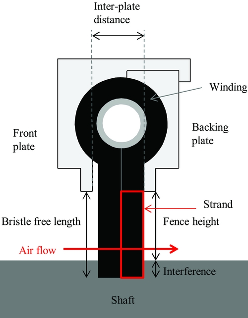
Figure 1. Cross section of a carbon fibre brush seal.
Both portions represent the front plate and the backing plate, who have identical radial clearance. The brush seal radial clearance is more commonly referred as the fence height. The front plate ensures protection from the upstream turbulent flow and from damages done by foreign particles. The backing plate provides support for the axially deflected bristle pack under the effect of pressure. It also provides minimum sealing capacity in case of a bristle pack failure. Both plates are usually made of stainless steel, nickel alloys or anodised aluminum. Brush seals are mounted with either a clearance, which represents the gap between the bristles tip and the shaft surface, or an interference, which can be defined as the distance between the front plate clearance and the bristle-free length.
3.0 TEST INSTALLATION
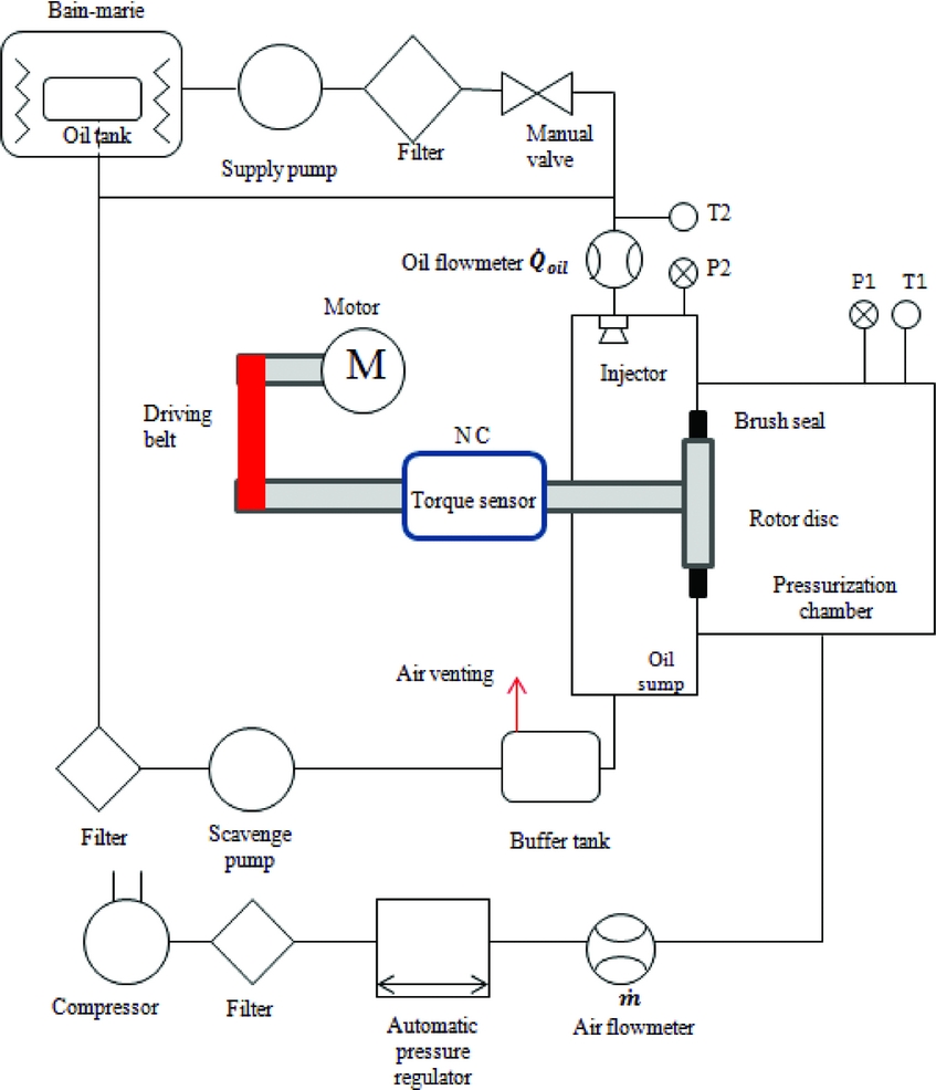
The test bench (called ATM02) that was developed to carry on the experimental investigation was built by ULB, in partnership with Safran Aircraft Engines, in the framework of the European Union project E-Break (Engine BREAKthrough components and subsystems). It is composed of two supply circuits, oil and air, and a rotating unit. The rotating unit reproduces the severe working conditions brush seals are submitted in bearing chambers. Oil is injected as a high-pressure jet in the oil sump, as the droplets drip on the internal walls. A pressurised chamber is mounted on the oil sump and provides the leakage flow to be measured through the brush seal. The brush seal is mounted at the interface of both chambers on a shaft that penetrates the oil sump. An inter-changeable rotor disc is mounted on the shaft, enabling different interference levels testing. Figure 2 shows a complete overview of the test rig. More details on the components can be found in the author’s previous paper(Reference Outirba and Hendrick12). In addition, Table 1 summarises the range of parameters of the installation.

Figure 2. ATM installation schematics.
Table 1 ATM02 range of parameters

Eight carbon fibre brush seals were tested. For the purpose of confidentiality, the authors were not allowed to communicate the bristles’ dimensions. However, some of the brush seal geometrical parameters require clarifications as follows:
-
• The lay angle will not be the subject of a parametric analysis. Indeed, the particular assembly process of carbon fibre brush seals does not allow the manufacturer to apply any initial lay angle during manufacturing. Instead, the winding coiled around the core causes the bristles to converge naturally towards the brush seal centre. Consequently, as these brush seals are not initially canted, no clearance levels were tested. The annular gap between the shaft and the bristle tips could not be closed due to eventual blow-down effect. Such configuration would inevitably leave excessive leakage, rendering any brush seal clearance analysis pointless.
-
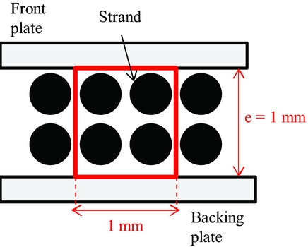
• A strand is defined as the winding piece that is located under the brush seal front plate or backing plate, as illustrated on Fig. 3. In other terms, one winding generates two strands in the brush seal axial direction: one located near the front plate and the other near the backing plate. Strands are composed of a determined number of carbon fibres. The number of fibres per winding (thus per strand) is constant along the brush seal inner diameter. Finally, regardless of the number of fibres per strand, it will always be assumed that two strands are spread over 1 mm in the axial direction.
Figure 3. Footprint of a brush seal without interference, and definition of the brush seal density.
-
• The brush seal axial density is defined as the number of bristles in the axial direction per mm2. It directly depends on the number of bristles per strands. Consequently to the previous assumption stating that 1 mm contains two strands, strands are always disposed by squared packing arrangements of 2 × 2 per mm2, the brush seal axial density is obtained by multiplying the number of fibres per strand by the number of strands found in an area of one mm2, as shown on Fig. 3.
-
• The choice of the maximum inter-plate distance (for brush seals 2, 4, 6 and 8) has been made such as it is ensured by the manufacturer that the bristle pack never enters in contact with the front plate in case of forward bending due to the bristle tips axial deflection. Such occurence will be discussed during the results analysis.

Table 2 lists the geometrical parameters of the tested brush seals, in function of their nominal value L, σ, and δ are, respectively, the bristle-free length, axial density, and the inter-plate distance. Also, eight rotor diameters will be tested. Their diameters will be expressed on Table 3 as a percentage of the brush seals internal diameter.
Table 2 Geometrical parameters of the tested brush seals
Table 3 Rotor disc diameters

4.0 RESULTS
4.1 Protocol and variables definition
The protocol observed for brush seal testing is as follows: each sample has been submitted to air progressive pressurisation until the limits of the test bench are reached (either the maximum flow delivered by the compressor or the maximum pressure measured by the differential pressure sensor), then the pressure is gradually decreased until zero. The process is repeated three times, for rotational speeds of 0, 200, 4.000, 8.000 and 12.000 rpm, in order to make sure the results obtained are repeatable. Finally, each brush seal is submitted to five to seven interference levels. The leakage flow, seal torque, upstream and downstream pressures and temperatures are recorded every second, and their evolution will be analysed in function of the operating conditions. To extend the range of applicability of the problem, the results will be expressed as a non-dimensional form. Using non-dimensional form is even more relevant as the air temperature and downstream pressure vary sensibly from one test to another. Using the Buckingham-pi theory, the mass flow will be computed in function of the pressure load such as:
 $$\begin{equation}
\frac{\dot{m}}{\sqrt{\rho _{1}} \sqrt{p_{1}} D L} = f \bigg (\frac{\Delta p}{p_{2}}\bigg )
\end{equation}$$
$$\begin{equation}
\frac{\dot{m}}{\sqrt{\rho _{1}} \sqrt{p_{1}} D L} = f \bigg (\frac{\Delta p}{p_{2}}\bigg )
\end{equation}$$
After applying the perfect gas law such as the upstream pressure and temperature appear, the definition becomes:
 $$\begin{equation}
\frac{\dot{m} \sqrt{R T_{1}} }{ p_{1} D L} = f\bigg (\frac{\Delta p}{p_{2}}\bigg )
\end{equation}$$
$$\begin{equation}
\frac{\dot{m} \sqrt{R T_{1}} }{ p_{1} D L} = f\bigg (\frac{\Delta p}{p_{2}}\bigg )
\end{equation}$$
The use of non-dimensional values allows to express the air mass flow
 $\dot{m}$
as a function of p
1 and T
1, respectively, the upstream pressure and temperature, the brush seal inner diameter D, the bristle free length L, the differential pressure across the seal Δp, and the downstream pressure p
2. Eventually, the non-dimensional values will be referred to as corrected mass flow and corrected differential pressure.
$\dot{m}$
as a function of p
1 and T
1, respectively, the upstream pressure and temperature, the brush seal inner diameter D, the bristle free length L, the differential pressure across the seal Δp, and the downstream pressure p
2. Eventually, the non-dimensional values will be referred to as corrected mass flow and corrected differential pressure.
 $$\begin{equation}
\dot{m}_c = f ( \Delta p_c )
\end{equation}$$
$$\begin{equation}
\dot{m}_c = f ( \Delta p_c )
\end{equation}$$
4.2 Hysteresis vs blow-down
The application of a pressure cycle on a brush seal results in higher air consumption in the depressurisation phase, and indicates a hysteresis phenomenon, as shown on Fig. 4. As demonstrated numerically by Zhao and Stango(Reference Zhao and Stango13), hysteresis phenomenon occurs because of inter-bristle friction forces appearing between bristles when they are deflected. A bending moment originates from the friction forces, and prevents full recovery of the bristles to their initial position once the differential pressure decreases. An additional clearance is added between the bristle pack and the shaft, and as a result, the air consumption increases.
Figure 4. Brush seal pressurisation cycle and hysteresis for brush seal 1/rotor 2.
In fact, it is important to mention that for carbon fibre brush seals, lift-off is prevalent over blow-down in carbon fibre brush seals. Indeed, carbon fibres present a low diameter of 5.10−3 mm, thus dramatically low moment of inertia, making these prone to axial deflection under air differential pressure. A parameter called hysteresis area H is introduced to determine which bristle pack designs are the most likely to suffer hysteresis. It is delimited by the ascending and descending curves, as illustrated on Fig. 4.
The hysteresis-induced leakage factor A represents the average additional leakage flow increase induced by hysteresis over one pressurisation/depressurisation cycle, and it is obtained by:
 $$\begin{equation}
A = \frac{H}{\Delta p_{c,max}}
\end{equation}$$\vspace*{-12pt}
$$\begin{equation}
A = \frac{H}{\Delta p_{c,max}}
\end{equation}$$\vspace*{-12pt}
 $$\begin{equation}
A = \frac{\int \dot{m}_{c,descending} \; {d}(\Delta p_c) - \int \dot{m}_{c,ascending} \; {d}(\Delta p_c) }{\Delta p_{c,max}}
\end{equation}$$
$$\begin{equation}
A = \frac{\int \dot{m}_{c,descending} \; {d}(\Delta p_c) - \int \dot{m}_{c,ascending} \; {d}(\Delta p_c) }{\Delta p_{c,max}}
\end{equation}$$
Then, A is normalized over a pressurisation/depressurisation cycle of Δp c, max = 1. This allows comparing the brush seals samples over the same baseline of pressures covered.
 $$\begin{equation}
A' = \frac{A}{\Delta p_{c,max}}
\end{equation}$$
$$\begin{equation}
A' = \frac{A}{\Delta p_{c,max}}
\end{equation}$$
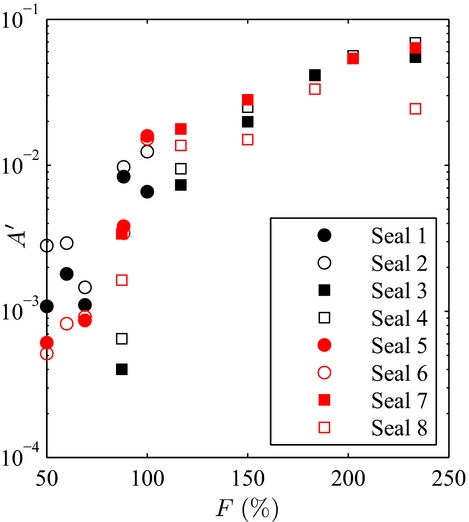
Figure 5 indicates that brush seals with the highest fence heights (expressed here in% of the nominal bristle-free length) are the most prone to hysteresis. Indeed, when considering the bristle as a cantilevered beam with a free end, the distributed load associated to differential pressure acts over a greater length of the bristle. As a result, the bristles' displacement in the axial direction is more important, and higher inter-bristle friction forces appear, thus higher bending moment and higher hysteresis. On the opposite, bristles with the lowest fence heights (below 100% of the nominal bristle-free length) present low hysteresis. As a consequence, the superfluous air consumption associated to hysteresis becomes limited. Rare occurences of blow-down were also encountered during testing for specific configurations, especially for short bristles with high interference. When the brush seal is initially mounted, the bristles are first deflected such as the bristle tips are oriented in the axial direction, as illustrated on Fig. 6. The bristles’ low moment of inertia, thus with high flexibility, prevents buckling, even with large interference. However, when the shaft rotates, the bristles’ tips are attracted by the shaft surface, such as they become oriented in the rotation direction. As a result, a lay angle appears (Fig. 7), allowing brush seals to demonstrate blow-down when differential pressure is applied. The development of the lay angle depends on the interference-to-fence height ratio. The larger the interference for a constant fence height, the bigger will be the newly formed lay angle, and the more important will be the blow-down forces. Blow-down forces are put in evidence through measuring of the seal torque, displayed on Fig. 8. On the opposite, brush seals with large fence heights have bristles who tend rather to be deflected in the downstream cavity direction in presence of differential pressure. Low contact forces with the shaft prevent the bristles to be mechanically angled during operation, hence, no blow-down is experienced, and lift-off becomes highly prevalent. Evidence of lift-off is suggested by sudden decrease of the seal torque when the pressure load is increased (Fig. 9). Hysteresis needs to be limited, and an ideal brush seal would have both curves to be confounded. In the frame of this study, only the ascending curve in function of the pressure load will be taken into consideration.

Figure 5. Evolution of brush seal hysteresis-induced leakage factor in function of the fence height.

Figure 6. Initial mounting of a carbon fibre brush seal.
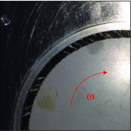
Figure 7. Formation of a brush seal lay angle.
Figure 8. Seal torque and leakage flow in presence of blow-down.
Figure 9. Seal torque and leakage flow in presence of lift-off.
4.3 Leakage flow model
In the meantime, it has been discovered that the evolution of the air consumption with the differential pressure is linear in dynamic conditions (Fig. 10). Moreover, the curve slope decreases as interference increases. This is simply explained by the fact that for one fixed bristle free length, increasing the interference decreases the fence height, which reduces the useful cross section of the brush seal. The equation describing the behaviour can be approximated with an analogy of Darcy’s law:
 $$\begin{equation}
\dot{m}_c = K_{p} \Delta p_c
\end{equation}$$
$$\begin{equation}
\dot{m}_c = K_{p} \Delta p_c
\end{equation}$$

Figure 10. Leakage performance of brush seal 1 in function of the interference at 4.000 RPM.
K p is defined as the dimensionless permeability of the brush seal. Eventually, the objective of this work is to define its dependency with the bristle pack geometrical parameters.
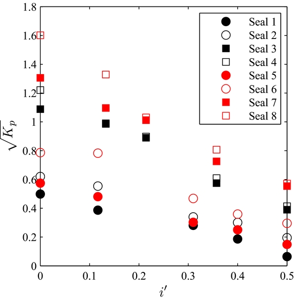
The evolution of brush seal 5 mounted with rotor 5 air consumption in function of the rotational speed is reported on Fig. 11. Significant differences occur between the static measurements and the low-speed ones, where the air consumption increases with the speed. The leakage flow increase from static dynamic conditions can be attributed to the bristles mechanical canting. The bristles tips are attracted by the shaft surface sliding due to friction, and bristles become oriented towards the direction of the shaft rotation. As a lay angle progressively appears, the brush seal interference diminishes and favours the increase of the air consumption. However, no leakage flow increase was recorded between 4.000 rpm and 18.000 rpm. It is suggested that the boundary layer that appears around the shaft has no effect on the air consumption. These results are consistent with Aksit et al(Reference Aksit and Aksoy14) observations, where it was concluded that speed had limited impact on the aerodynamic lift developed between the bristles and rotor surface. This observation will facilitate the air consumption analysis, which is freed from the rotational speed influence. The model will only exploit the measures taken above 4.000 rpm. Figure 12 represents the evolution of K p with the relative interference i′, that is defined as the ratio of the interference i with the bristle free length L:
 $$\begin{equation}
i^{\prime } = \frac{i}{L}
\end{equation}$$\vspace*{-8pt}
$$\begin{equation}
i^{\prime } = \frac{i}{L}
\end{equation}$$\vspace*{-8pt}
Figure 11. Leakage performance of brush seal 5 with rotor 5, in function of the rotation speed.

Figure 12. Brush seal permeability in function of the relative interference.
The results were recorded for the rotational speeds of 4.000, 8.000 and 12.000 rpm. The brush seal permeability decreases when the relative interference increases, regardless of other parameters. Also, the evolution of K
p
is parabolic rather than linear. Indeed, the lower the interference, the more likely the bristle tips are lifted away from the shaft surface due to air pressure load. As a result, air flows with more ease through the brush seal, and the air consumption increases. Therefore, a linear relationship between
 $\sqrt{K_{p}}$
and i/L can be retrieved, and the brush seal non-dimensional permeability is expressed as:
$\sqrt{K_{p}}$
and i/L can be retrieved, and the brush seal non-dimensional permeability is expressed as:
 $$\begin{equation}
\sqrt{K_{p}}= A - B \; i^{\prime } ,
\end{equation}$$
$$\begin{equation}
\sqrt{K_{p}}= A - B \; i^{\prime } ,
\end{equation}$$
with A and B being coefficients to be calibrated using the experimental data. Also, A and B are defined as the following combination of functions expressing the influence of one parameter.
 $$\begin{equation}
A = f_{1}(L) f_{2}(\sigma ) f_{3}(\delta )
\end{equation}$$\\
$$\begin{equation}
A = f_{1}(L) f_{2}(\sigma ) f_{3}(\delta )
\end{equation}$$\\
 $$\begin{equation}
B = f_{4}(L) f_{5}(\sigma ) f_{6}(\delta )
\end{equation}$$
$$\begin{equation}
B = f_{4}(L) f_{5}(\sigma ) f_{6}(\delta )
\end{equation}$$
Each parameter contribution will be isolated by comparing the curve coefficients between two brush seals that only differ by one geometrical parameter.
4.3.1 Influence of the bristle-free length
It is acknowledged that for one chosen interference level, increasing the bristle free length increases the fence height, thus the brush seal permeability. Brush seals 1 and 3 are, respectively, compared with brush seals 5 and 7, who have longer bristles. L acts simultaneously on the slope of the K p curve (the greater the bristle free length, the closer to a relative interference of 1 the x-intercept will be) and on the y-intercept. Identification of f 1 and f 5 leads to curves that are made independent from the bristle-free length and plotted on Fig. 13. Brush seals that have the same density and inter-plate distance are now confounded into one same linear curve. f 1 and f 5 are made explicit such as:
 $$\begin{equation}
f_{1} = \frac{L}{L_{0}}
\end{equation}$$\\
$$\begin{equation}
f_{1} = \frac{L}{L_{0}}
\end{equation}$$\\
 $$\begin{equation}
f_{1} = \bigg ( \frac{L}{L_{0}}\bigg )^{3/4}
\end{equation}$$
$$\begin{equation}
f_{1} = \bigg ( \frac{L}{L_{0}}\bigg )^{3/4}
\end{equation}$$
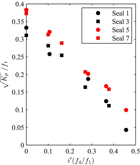
Figure 13. K p in function of i/L made independent from the influence of the bristle-free length.
In order to keep the functions non-dimensional, an arbitrary reference length L 0 has been introduced, equalling 1 mm. It corresponds to the order of magnitude of the bristle length.
4.3.2 Influence of density
Before investigating the effect of axial density, an additional non-dimensional parameter has to be introduced. The porosity ε (also used by Pugachev et al(Reference Pugachev and Helm7) for their brush seal porous model) of a brush seal is defined as the volume of voids over the volume of voids and solids (here, the bristles) that define the bristle pack, when the interference equals zero. The bristles are assumed to be parallel cylinders of height L and diameter d. Hence, the porosity is expressed as a function of the bristle pack density σ (itself depending on the number of strands contained in 1 mm2) and the rotor area where the bristles are spread, between the front and backing plates.
 $$\begin{equation}
\epsilon = \frac{ \pi \; D^2 \; e \; L - \pi \; D^2 \; e \; \sigma \; \pi \; (d^2/ 4) \; L}{ \; \pi \; D^2 \; e \; L}
\end{equation}$$\\
$$\begin{equation}
\epsilon = \frac{ \pi \; D^2 \; e \; L - \pi \; D^2 \; e \; \sigma \; \pi \; (d^2/ 4) \; L}{ \; \pi \; D^2 \; e \; L}
\end{equation}$$\\
 $$\begin{equation}
\epsilon = 1 - \frac{\sigma \pi d^2}{4}
\end{equation}$$
$$\begin{equation}
\epsilon = 1 - \frac{\sigma \pi d^2}{4}
\end{equation}$$
Increasing the axial density decreases the brush seal porosity. Using the same logic as for the previous parameter, brush seals 1 and 5 will be, respectively, compared with brush seals 3 and 7, as the latter two present lower densities. Identification of functions defined by density lead to setting f 2 being equal to f 6. Brush seals that have the same bristle free length and inter-plate distance are now confounded into one same linear curve, such as:
 $$\begin{equation}
f_{2} = f_{5} = \epsilon ^{0.1}
\end{equation}$$
$$\begin{equation}
f_{2} = f_{5} = \epsilon ^{0.1}
\end{equation}$$
The brush seal permeability curves made independent of density are plotted on Fig. 14.
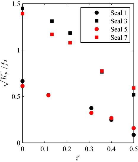
Figure 14. K p in function of i/L made independent from the influence of density.
4.3.3 Influence of the inter-plate distance
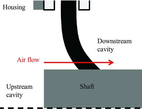
Increasing the inter-plate consists in moving away the front plate from the bristle pack, while the backing plate is not displaced, remaining close to the bristle pack. The bristle pack is deflected in the axial direction under the effect of pressure (almost constant along the fence height region), towards the downstream cavity. The subsequent space that is left in-between allows bristles to be forward bending in the inter-plate region (due the backing plate providing support during deflection) without being blocked by the front plate, as illustrated in Fig. 15. The bristle pack avoids being stiffened due to blocking by the front plate, and the friction torque is reduced while increasing the air consumption as shown on Fig. 16. The seal torque values were expressed in percentage of the maximum torque recorded, for brush seal 1 at Δp c = 0.
Figure 15. Brush seal deflection under pressure load.
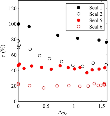
Figure 16. Brush seals 1, 2, 5 and 6 seal torque with rotor 4 at 4.000 RPM.
The comparison features brush seals 1, 3, 5 and 7 with brush seals 2, 4, 6 and 8. Results also show that the percentage increase of air consumption is lower for long bristles (up to 9%) than for short bristles (up to 30%), which are more constrained under the effect of air pressure. The influence of the inter-plate distance depends rather on the ratio between the bristlefree length L, and the bristle total length, defined by the distance between the brush seal core and the bristle tips L tot . The higher the ratio, the higher will be the front displacement of the bristles in the inter-plate region for a fixed bristle tip displacement towards the downstream cavity. Finally, δ acts on the Y-intercept and on the slope. Indeed, the air consumption is increased, but the minimum relative interference at which the bristle pack is squeezed such that it does not allow any air to flow remains identical; therefore, the slope increases. Finally, the empirical functions defining the influence of the inter-plate distance are:
 $$\begin{equation}
f_{3}= \left\lbrace
\begin{array}{l@{\quad}l}
1 + 0.2112 \big( 1-\frac{L_{tot}}{L} \big )^{3/4}, & \text{if } \delta \gg \ e \\
1, & \text{if } \delta = e \end{array}\right.
\end{equation}$$
$$\begin{equation}
f_{3}= \left\lbrace
\begin{array}{l@{\quad}l}
1 + 0.2112 \big( 1-\frac{L_{tot}}{L} \big )^{3/4}, & \text{if } \delta \gg \ e \\
1, & \text{if } \delta = e \end{array}\right.
\end{equation}$$
 $$\begin{equation}
f_{6} = \left\lbrace
\begin{array}{l@{\quad}l}
1 + 0.14 \big ( 1-\frac{L_{tot}}{L} \big )^{1/4}, & \text{if } \delta \gg \ e\\
1, & \text{if } \delta = e \end{array}\right.
\end{equation}$$
$$\begin{equation}
f_{6} = \left\lbrace
\begin{array}{l@{\quad}l}
1 + 0.14 \big ( 1-\frac{L_{tot}}{L} \big )^{1/4}, & \text{if } \delta \gg \ e\\
1, & \text{if } \delta = e \end{array}\right.
\end{equation}$$
The front plate is assumed to be sufficiently far away from the bristle pack, such as the latter is never blocked by the front plate during the application of a pressure load. Figure 17 features brush seals that have the same density and bristle-free length, being confounded into one same linear curve.
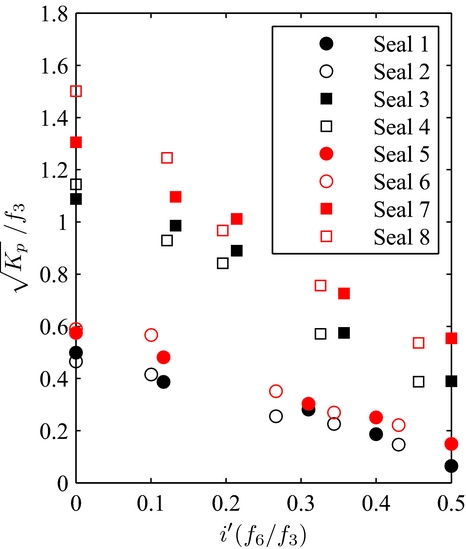
Figure 17. K p in function of i/L made independent from the influence of the inter-plate distance.
4.3.4 Determination of the brush seal Kp in function of the geometrical parameters
Ultimately, with all the empirical functions having been determined, all eight brush seals permeability equations can be reunited in one single general function, displayed on Fig. 18. The experimental data is inter-polated by a linear function with an R 2 of 86% and a variance of 0.039. The general equation describing the leakage performance in function of the geometrical parameters in dynamic conditions is the following:
 $$\begin{equation}
A = \frac{\sqrt{K_{p}}}{f_{1}f_{2}f_{3}} = 0.419 - 0.717 \frac{i}{L}\frac{f_{4}f_{5}f_{6}}{f_{1}f_{2}f_{3}}
\end{equation}$$
$$\begin{equation}
A = \frac{\sqrt{K_{p}}}{f_{1}f_{2}f_{3}} = 0.419 - 0.717 \frac{i}{L}\frac{f_{4}f_{5}f_{6}}{f_{1}f_{2}f_{3}}
\end{equation}$$
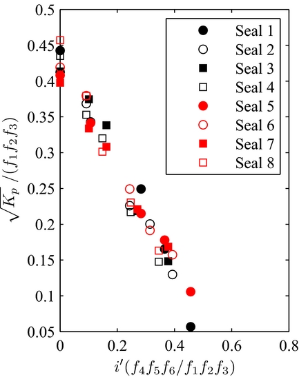
Figure 18. K p in function of i/L made independent from every geometrical parameter.
4.4 Limitations of the model
The development of the calculation model has been made with the assumption that the air consumption is proportional to the differential pressure. However, this is not always true. For brush seals with long bristles, the evolution of the air consumption is rather parabolic. The bristle pack is lifted away from the shaft when the differential pressure reaches a certain level. An annular gap between the bristles tip and the shaft surface is left, and the air consumption increases even more. Nevertheless, the performance of such brush seals would be regarded as very poor, and to avoid excessive bristle tip displacements, it is recommended to use smaller bristles. The leakage performance curve of brush seal 3 mounted with rotor 3 is plotted on Fig. 19. The other specific case that does not fit the model is a consequence of short bristles being angled under the effect of rotational speed. The brush seal becomes prone to blow-down effect. Blow-down causes bristles to close down the shaft because of an angular moment created. As a result, the air consumption increase rate with the differential pressure is attenuated beyond the non-dimensional pressure ratio of 0.5, as shown in Fig. 20. The K p curve is shifted upwards or downwards, whether the bristle pack is subjected to blow-down effect or to lift-off from the shaft surface. The higher the pressure difference, the more accurate will be the air consumption prediction.

Figure 19. Leakage flow in function of the pressure gradient for the combination brush seal 3/rotor 3.
Figure 20. Leakage flow in function of the pressure gradient for the combination brush seal 2/rotor 2.
To minimise the brush seal air consumption, increasing the density is not mandatory, as fence height proves to be the main design parameter. Front and backing plates should be kept as close as possible to the bristle pack. One could argue that brush seal sizing would only consist in choosing short bristles with high interference, in order to minimise the brush seal leakage flow, with sufficiently high fence height to accommodate thermal or centrifugal dilatations. However, the identification of an optimum design of a brush seal must also take into account the frictional torque that is developed. For instance, experience has shown that high interference levels coupled with short bristles or high-density generate high friction(Reference Outirba and Hendrick15). Consequently, heat generation and wear rates are more important. A confirm has to be made between dissipated heat and leakage flow in function of the aero-engine flight phase, to maximise the life service while meeting the engine requirements.
5.0 CONCLUSION
ULB, in collaboration with Safran Aircraft Engines, developed a new test rig reproducing the realistic working conditions the brush seals will be submitted. So far:
-
• Carbon fibre brush seals have been identified as prone to bristle lift-off under differential pressure rather than blow-down, because of the fibres’ extremely low moment of inertia, making these very flexible.
-
• In addition, as carbon fibres brush seals’ particular manufacturing process does not allow to apply an initial lay angle, blow-down occurs only in specific configurations where the interference-to-fence height ratio is high enough. Low fence heights reduce the bristles’ axial displacement towards the downstream cavity under differential pressure. Consequently, bristles are canted under the effect of friction and shaft rotation. The apparition of a lay angle allows demonstration of blow-down.
-
• Empirical relations have been developed to predict the evolution of the air consumption. An analogy of Darcy’s law has been established, with the brush seal’s dimensionless permeability directly depending on the following geometrical parameters: bristle free length, density, inter-plate distance, number of strands in the axial direction, and interference.
-
• In an attempt to generalise the formula to wider applications, operating conditions such as pressure, temperature and rotational speed have been taken into account.
-
• The primary parameter reducing the leakage rate of a brush seal is the fence height. Consequently, short bristles are preferred, with low interference level to limit the brush seal torque, thus heat generation.
-
• The impact of density is less significant than the fence height, which allows to use low-density bristle packs. Finally, front and backing plates should be kept as close as possible to the bristle pack.
The air consumption prediction model will be completed by ULB with an analysis on the seal torque and heat generation, which will help identifying the optimum brush seal/rotor diameter configuration. In addition to the analysis in dry conditions, the influence of oil on leakage performance, and the seal torque analysis will be the subject of future publications. Ultimately, the best samples performance-wise will be submitted through endurance testing, as the evolution of leakage and friction with time will also be implemented in the prediction model.
ACKNOWLEDGEMENTS
It is gratefully acknowledged that the research leading to these results has received funding by the European Union Seventh Framework Program FP7/2007-2013 under grant agreement n 314366 (E-Break project lead by Safran Helicopter Engines).

The authors also would like to thank Safran Aircraft Engines for their collaboration and help during the development of the test bench and the related test campaign.