


INTRODUCTION
Nuclear fusion ignition by inertial confinement induced by lasers is very promising and is on the forefront of research today (Velarde & Carpentero-Santamaria, Reference Velarde and Carpintero-Santamaria2007; Mima et al., Reference Mima, Murakami, Nakai and Eliezer2009). It is expected to be achieved with the mega-joule laser of a few nanoseconds pulse duration by Livermore National Laboratory (Moses, Reference Moses2009). The target and the driver pulse shape are specially designed in order to start ignition at the center (a spark) of the compressed fuel (Lindl, Reference Lindl1997; Rosen, Reference Rosen1999; Atzeni & Meyer-Ter-Vehn, Reference Atzeni and Meyer-Ter-Vehn2004). The rest of the fuel is heated by alpha particles produced in the deuterium tritium (DT) reactions.
In order to ignite a DT target with less energy, it was suggested (Basov et al., Reference Basov, Guskov and Feoktistov1992; Tabak et al., Reference Tabak, Hammer, Glinsky, Kruer, Wilks, Woodworth, Campbell, Perry and Mason1994) to separate the drivers that compress and heat the target. This idea is called fast ignition (FI). First, the pellet is compressed by a laser system with a few nanoseconds pulse duration; then a second driver, for example, a multi-petawatt laser beam, ignites a small part of the pellet. In this case, the alpha particles produced in the DT reactions heat the rest of the target.
The main problem of FI is that the laser pulse does not penetrate directly into the compressed target since the electron density is on the order of 1024 cm−3. Therefore, many schemes of FI were suggested: (1) the laser energy is converted into electrons that ignite the target (Norreys et al., Reference Norreys, Allot, Clarke, Colliers, Neely, Rose, Zepf, Santala, Bell, Krushelnick, Dangor, Woolsey, Evans, Habara, Norimatsu and Kodama2000), (2) the laser energy is converted into protons that ignite the target (Roth et al., Reference Roth, Cowan, Key, Hatchett, Brown, Fountain, Johnson, Pennington, Snavely, Wilks, Yasuike, Ruhl, Pegoraro, Bulanov, Campbell, Perry and Powell2001; Brenner et al., Reference Brenner, Green, Robinson, Carroll, Dromey, Foster, Kar, Li, Markey, Spindloe, Streeter, Tolley, Wahlstrom, Xu, Zepf, Mckenna and Neely2011; Pae et al., Reference Pae, Choi and Lee2011; Torrisi et al., Reference Torrisi, Caridi and Giuffrida2011). (3) A gold cone was stuck in the spherical pellet (Kodama et al., Reference Kodama, Norreys, Mima, Dangor, Evans, Fujita, Kitagawa, Krushelnick, Miyakoshi, Miyanaga, Norimatsu, Rose, Shozaki, Shigemori, Sunahara, Tampo, Tanaka, Toyama, Yamanaka and Zepf2001) in order to solve the preheating problem. (4) FI is induced by plasma jets (Martinez Val & Piera, Reference Martinez Val and Piera1997; Velarde et al., Reference Velarde, Ogando, Eliezer, Martinez Val, Perlado and Murakami2005) that are produced by the same laser system that compresses the pellet. (5) The FI is accomplished by the plasma flow created from a thin exploding pusher foil (Caruso & Strangio, Reference Caruso and Strangio2001; Guskov, Reference Guskov2001; Krasa et al., Reference Krasa, Lorruso, Nassisi, Velardi and Velyhan2011). (6) Plasma blocks for FI were also suggested (Hora et al., Reference Hora, Badziak, Glowaks, Jablonski, Skladanovski, Osman, Cang, Zhang, Miley, Peng, He, Zhang, Rohlena, Ullschmied and Jungwirth2005, Reference Hora, Miley, Flippo, Lalousis, Castillo, Yang, Malekynia and Ghoranneviss2011). (7) The old impact fusion with the help of the cone (Murakami et al., Reference Murakami, Nagatomo, Azechi, Ogando, Perlado and Eliezer2006; Azechi et al., Reference Azechi, Sakaiya, Watari, Karasik, Saito, Ohtani, Hosoda, Shiraga, Nakai, Shigemori, Fujiok, Murakami, Johzaki, Gardner, Colombant, Bares, Velikovich, Aglitskiy, Weaver, Obenchain, Eliezer, Kodama, Norimatsu, Fujita, Mima and Kan2009) was suggested as an alternative to the petawatt laser ignition. (8) The features of shock wave collision (Jackel et al., Reference Jackel, Salzmann, Krumbein and Eliezer1983) were introduced into the FI with a laser induced strong shock wave (Betti et al., Reference Betti, Zhou, Anderson, Perkins, Theobald and Solodov2007). A novel scheme of combining the FI fusion with a shock wave by a foil impact was recently published (Eliezer & Martinez Val, Reference Eliezer and Martinez Val2011).
In the next section, we suggest to accelerate micro-foils to relativistic velocities by using a multi-terawatt laser. From momentum and energy conservation a two model equations are obtained and solved analytically in a consistent way. The maximum velocity achieved so far was reported (Azechi et al., Reference Azechi, Sakaiya, Watari, Karasik, Saito, Ohtani, Hosoda, Shiraga, Nakai, Shigemori, Fujiok, Murakami, Johzaki, Gardner, Colombant, Bares, Velikovich, Aglitskiy, Weaver, Obenchain, Eliezer, Kodama, Norimatsu, Fujita, Mima and Kan2009) to be about 1000 km/s and used for a DT impact fusion device (Murakami et al., Reference Murakami, Nagatomo, Azechi, Ogando, Perlado and Eliezer2006). In this work, velocities by an order of magnitude higher are recommended for impact fusion. Due to the significantly higher temperature that one gets in this case, this scheme may be appropriate also for the clean proton-boron11 fusion (Eliezer & Martinez Val, Reference Eliezer and Martinez Val1998).
After the relativistic acceleration of the micro-foil chapter, in the following section, we propose to use the very high velocities of the micro-foil for impact fusion of a pre-compressed cylinder (Basko et al., Reference Basko, Churazov and Aksenov2002; Guskov, Reference Guskov2005; Nakamura et al., Reference Nakamura, Sentoku, Matsuoka, Kondo, Nakatsutsumi, Norimatsu, Shiraga, Tanaka, Yabuuchi and Kodama2008; Vauzour et al., Reference Vauzour, Perez, Volpe, Lancaster, Nicolai, Batani, Baton, Beg, Benedetti, Brambrink, Chawla, Dorchies, Fourment, Galimberti, Gizzi, Heathcote, Higginson, Hulin, Jafer, Koster, Labate, Mackinnon, Macphee, Nazarov, Pasley, Regan, Ribeyre, Richetta, Schurtz, Sgattoni and Santos2011). The conclusion of the ideas of this work is discussed in the last section.
RELATIVISTIC ACCELERATION OF MICRO-FOILS
The ponderomotive force per unit volume is related to the gradient of the radiation pressure P L. If the laser propagates in vacuum with irradiance I L and hits a sharp boundary, a solid-vacuum in our case, then the radiation pressure is (Eliezer, Reference Eliezer2002)
R is the reflection from the boundary and c is the speed of light. For IL >> 1016 W/cm2 the radiation pressure is the dominant pressure at the solid-vacuum interface. A very high power laser on the order of multi-petawatts with very short pulse duration (about picoseconds) accelerates a solid micro-foil to very high velocities. In this case, the Newton second law in the longitudinal direction (direction of the laser beam) can be described by the following equation
![\eqalign{&\lpar 1 + R\rpar \left(I_L \over c \right)S = m_0 {{\rm \gamma}^3} {dv \over dt}\comma \cr &{\rm \gamma} = {1 \over \left[1 - v^2 / c^2 \right]^{1/2}}\comma} \eqno\lpar 2\rpar](https://static.cambridge.org/binary/version/id/urn:cambridge.org:id:binary:20151021072132278-0431:S0263034611000863_eqn2.gif?pub-status=live)
S is the cross-section area of a micro-foil with a thickness l and with a density ρ0, so that the mass is m 0 = ρ0Sl and dv/dt is the longitudinal acceleration. The micro-foil moves with a velocity v and γ is the relativistic factor. The momentum conservation of Eq. (2) has to be satisfied together with the energy conservation
W L is the laser energy since we have assumed a constant irradiance I L during the laser pulse duration 0 < t < τL. 1-R is the laser absorption, ηK is the efficiency from the absorbed laser energy to the kinetic energy of the micro-foil, and γm is the relativistic factor at the end of the laser pulse duration τL.
We shall solve Eqs. (2) and (3), the model equations, in the following dimensionless units

In our model Eqs. (4i) and (4ii) δ and R are given, there are two equations (i) and (ii) with two unknowns β and η that are solved simultaneously satisfying the constrains
In order to get a feeling of the acceleration suggested in this work, the following numerical example is appropriate: a multi-petawatt laser defined by I L =3 × 10²¹ W/cm2, τL = 1 ps, W L = 30 kJ accelerating a micro-foil with dimension S = 10−5cm2 (about 30 µm × 30 µm), l = 1 µm, density about 1g/cm3 implying a value of δ ~ 1/3.
The exact solution of the differential equation 4(i) for β is

Note that for zero laser energy input the velocity goes to zero, while for infinite energy the velocity goes to the speed of light as expected, namely
Substituting our solution for β into equation 4(ii) we get
![{\rm \eta} = \lpar 1 + R\rpar \left[{\sqrt{\Delta^2 + 1} - 1 \over \Delta} \right].\eqno\lpar 8\rpar](https://static.cambridge.org/binary/version/id/urn:cambridge.org:id:binary:20151021072132278-0431:S0263034611000863_eqn8.gif?pub-status=live)
The values of β and η for R = 0.2, 0.5, and 0.8 are plotted in Figure 1. Since η < 1 we get a maximum value of Δm for every R


Fig. 1. (Color online) The relativistic velocity β for the micro-foil and the efficiency η for R = 0.2, 0.5 and 0.8 as a function of the dimensionless laser energy Δ.
It is interesting to point out that the relativistic equations of momentum and energy conservation, as given in Eq. (4), have a solution only in a limited domain of energy Δ < Δm.
A FI SCHEME
The high compression of the main fuel is achieved by shock waves and by the accumulation of matter during the stagnation of the implosion of the target shell. We suggest using the high velocity micro-foil to ignite the pre-compressed cylinder shell as described schematically in Figure 2. The initial mass, density, and dimensions of the fuel (DT for example) cylinder shell are accordingly M 0, ρ0 and radius R 0, thickness ΔR 0 and length L. The cylinder length is related to the final radius of compression R C by a physical parameter A L, L = A LR C, and the thickness shell is fixed by an aspect ratio R 0/ΔR 0 = A. The equality of the initial mass and the final mass (before ignition) of the compressed fuel M C = M 0 implies

where the compressed density is ρC.
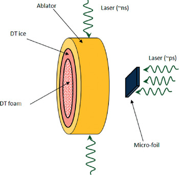
Fig. 2. (Color online) Schematic configurations of impact fusion of a pre-compressed cylinder.
The gain G is given by

W d is the driver energy composed of two terms: the compression laser energy W LC and the ignition energy W LI given by the laser energy W L that accelerates the micro-foil defined in Eq. (3) and discussed in the previous section. q DT = 3.39 × 10⁸ kJ/g is the energy output per gram and ϕ is the burning fraction in the DT fusion given by

In order to compress and heat the main fuel, defined by its pressure PC and temperature TC one requires driver energy WLC given by the following energy conservation (Eliezer et al., Reference Eliezer, Murakami and Martinez Val2007)
ηC is the efficiency from laser to thermal energy, ɛF is the Fermi energy, and α is related to the electron degenerate quantum pressure P deg (Eliezer & Ricci, Reference Eliezer and Ricci1991; Eliezer et al., Reference Eliezer, Ghatak and Hora2002 ) for DT according to the relations
The numerical factor in Eq. (14) is given for using c.g.s. units. n e is the electron density, h is the Planck constant, m e is the electron mass and the effective temperature T C and pressure P C are defined for the DT plasma via P C = 2n ek BT C. Simulations show that αC equals about 3 is a reasonable number (Rosen, Reference Rosen1999). Using Eqs. (13) and (15) for the DT fusion case one gets

For example, from Eqs (10)–(12) with ϕ = 0.3, if one has ρC = 1000 g/cm3 (Azechi et al., Reference Azechi, Jitsuno, Kanabe, Katayama, Mima, Miyanaga, Nakai, Nakai, Nakaishi, Nakatsuka, Nishiguchi, Norreys, Setsuhara, Tagagi, Yamanaka and Yamanaka1991), ρ0 = 0.2 g/cm3, A = 20, A L = 10 then L = 0.0447R 0, ρCR C = 3g/cm2, R 0 = 0.474 cm, and M C = 0.848 mg. Using Eq. (16) we get W LC = 0.82 MJ and for these set of parameters one gets from Eq. (11) a gain of G ~ 100 can be achieved.
We discuss now the ignition physics. The ignition in our scheme is not caused by an induced shock wave. A shock wave ignition will require an accelerating laser pulse with energy about two orders of magnitude or more larger than suggested above. This can be easily seen from the high pressure (P) shock wave thickness (d) estimated from the equality of pressures at the interface between the flyer and the compressed target. Since P ~ ρ0u 02 ~ ρCu C2 and the shock wave transition time in the flyer with a thickness l is t = l/u 0 one gets a shock wave thickness d of the order d ~ (ρ0/ρC)1/2l. In the above scheme, (ρ0/ρC) ~ 0.001 and l ~ 1 µm implying d ~ 0.03 µm. The ignition criterion is based on the requirement that the alpha particles created in the DT reaction are reabsorbed in the hot spot implying a “ρR” value larger than 0.3 g/cm2 for a temperature about 10 keV and larger values for higher temperatures. In the shock wave ignition “ρR” = ρCd ~ l(ρ0ρC)1/2 ~ 0.003 g/cm2 for our case that is two order of magnitude too low. From this ignition criterion in the hot spot, we need to increase the foil thickness by two orders of magnitude that imply the undesired result of increasing the accelerating driver energy by two orders of magnitude.
Our scheme is based on heat wave ignition. The local absorption of the flyer energy is associated with the creation of a temperature gradient and a thermal flux to transport the absorbed energy. If the interaction of the impact is very short, on the order of 1 ps or less, the hydrodynamic motion does not have time to develop, and therefore in these cases the heat transport is dominant. Electrons or X-rays may serve as heat carriers. For nonlinear transport coefficient, like the electron conductivity, we expect that the energy transport is caused by a heat wave. This heat wave plays the important role in the inertial confinement fusion during the ignition process.
The nonlinear heat transport equation and the energy conservation are described accordingly (Zeldovich & Raizer, Reference Zeldovich, Raizer, Hayes and Probstein1966; Eliezer, Reference Eliezer2002)
T is the temperature, x is the position, t is time, W S [erg] is the deposited energy into the hot spot area S [cm2], ρC is the density of the compressed target, C V [erg/(g·K)] is the specific heat at constant volume and, a is a constant related to the thermal diffusivity χ[cm2/s] = aT n. The solution of these equations for n = 5/2 is

Solution of this equation for three different times t 1 > t 2 > t 3 are shown in Figure 3. T 0 is taken as 100 keV, 20 keV, and 10 keV for the appropriate times t 1 > t 2 > t 3. The first T 0 was chosen from the energy relation (1/2)ρ0u 02 ~ 3(k BT) ρC/(2.5 m p) where m p is the proton mass. This implies an initial temperature T[keV] ~ 106(ρ0/ρC)β2. For ρ0/ρC ~ 0.001 and β = 0.3 we get T ~ 100 keV. The energy W s and the mass in the hot spot M s are


Fig. 3. (Color online) Solution of the heat wave equation for nonlinear coefficient n = 5/2 at three different times t 1 > t 2 > t 3.
W LI is the laser driver that accelerates the foil, ηs is the efficiency from the laser to the thermal energy of the hot spot, and T s is the hot spot temperature changing with time as can be seen from Figure 3. Ignition requires ρx f = “ρR” ≈ 0.3 g/cm2 and 2 g/cm2 for T s = 10 keV and 100 keV accordingly, and since the density is constant during the heat wave transition we require x f = 3 µm for a temperature of 10 keV or a larger x f in agreement with the alpha mean free path.
Using the ignition criterion and Eq. (20) for T = 100 keV and T = 10 keV we need accordingly: M s(100 keV) = 1.8 × 10⁻⁵g, W s(100 keV) = 5.7 × 10⁵ J and M s(10 keV) = 0.27 × 10⁻⁵g, W s(10 keV) = 8.5 × 10³ J. From Figure 3 one can see that during the change in temperature from 100 keV to 10 keV the x f changes by about a factor of 10 without change in the density. Therefore, we claim that the criterion for the 10 keV case is the relevant one and using this value we need a laser driver for accelerating the foil of about 85 kJ assuming that the efficiency from the laser to the thermal energy of the hot spot ηs is 10%.
DISCUSSION
In this work, the acceleration of a micro-foil to relativistic velocities is suggested. The accelerating force is the ponderomotive force induced by a multi-petawatt laser on the interface of a vacuum with the micro-foil solid target. The extremely high velocities of the micro-foil can be achieved due to the very short time duration (picoseconds) of the laser pulse. In these cases, the ablation pressure is negligible relative to the ponderomotive pressure. The model equations for this acceleration are based on momentum and energy conservation as given in equations (4i) and (4ii). The two unknown of these equations are the micro-foil velocity β (in units of the speed of light) and the energy efficiency η transferred from the laser to the micro-foil. The model is subjected to constrain given in Eq. (5). The solution of this model is given in Eqs. (6) and (8) and described in Figure 1. The equations of our model have a solution only for a dimensionless energy (Δ) smaller than a value dependent on the laser reflection R as calculated in Eq. (9). This effect can be understood from the model since both the acceleration force and the kinetic energy given to the micro-foil are linear function with Δ while the relativistic formulas are different nonlinear functions in β.
Our model is using the acceleration before the hydrodynamic instabilities start their destructive action. Similarly, all high pressure shock wave experiments are based on the fact that diagnostics is very fast and the experiment ends before the foil-target disassemble. Taking into account the material strength, the shock wave transient time through the foil and the relative motion between the fluid particles there should be a relaxation time τ0 before the hydrodynamic instabilities break the foil. It is out of the scope of this paper to analyze this problem in depth, however using a simple dimensional analysis we estimate

G is the shear modulus and ρ is the density of the accelerated matter and l is foil thickness and we assume that 1% deformation will trigger a foil breaking. For example, for aluminum 6061one has G = 0.276 Mbar, ρ = 2.70 g/cm3 and taking a micro-foil with l =1 µm one gets τ0 = 3.1 ps. Although this is a very crude approximation, we suggest in this case that acceleration during a time of about 3 ps will keep the micro-foil intact even for extremely high acceleration like the one suggested in this paper.
For a further order of magnitude check, the Rayleigh-Taylor instabilities were calculated taking into account the shear stresses of the matter (Piriz et al., Reference Piriz, Lopez Cela, Cortazar, Tahir and Hoffmann2005). It is interesting to point out that this calculation for the accelerations of 1020 cm/s2 and 1021 cm/s2 yields a τ0 on the order of one picosecond, consistent with our rough estimation of Eq. (19).
This accelerated micro-foil is used to ignite a pre-compressed cylindrical shell containing the imploded plasma. Our scheme is based on heat wave ignition. This approach has the advantage of separating geometrically the nanoseconds lasers that compress the target with the picosecond laser that accelerates the foil. In this paper extremely high velocities are recommended for impact fusion. Due to the significantly higher temperature that one gets in this case this scheme may be appropriate also for the clean proton-boron11 fusion. The present model suggests that nuclear fusion by a micro-foil impact ignition could be attained with existing present technology.
APPENDIX
One has to solve exactly equation (4i) as has been done in the text of this paper. Nevertheless we show here (for pedagogical reasons) the solution of equation (4i) with the approximation often used for short laser pulses, namely dβ/dt ~β/τL. This approximation leads to a cubic equation in β2:

The three roots of this cubic equation are (β12, β+2, β−2):

![\hskip-12pt\eqalign {S_\pm &= \left[r \pm \left(q^3 + r^2 \right)^{1/2} \right]^{1/3} = \left({1 \over 2 \Delta^2} \right)^{1/3} \cr &\qquad \left[1 \pm \left(1 - {4 \over 27 \Delta^2} \right)^{1/2} \right]^{1/3} }](https://static.cambridge.org/binary/version/id/urn:cambridge.org:id:binary:20151021072132278-0431:S0263034611000863_eqnU3.gif?pub-status=live)

For q 3 + r 2 > 0 one has a real root and a pair of complex conjugate roots for β2. This case is not physical in our problem since the real root is larger than 1 (β >1). If q 3 + r 2 = 0 all roots are real and two are equal, while for q 3 + r 2 < 0 all roots (of β2!) are real. In the last case one gets
The three roots of our cubic equation in this case are
![\hskip-65pt\eqalign {&{{\rm \beta}_1}^2 = 1 + 2 \left({1 \over 3 \sqrt{3}} \right)^{1/3} \left({1 \over \Delta} \right)\cr &\qquad \cos \left[{1 \over 3} {\rm arcsin} \left(\sqrt{1 - \left({27 \Delta^2 \over 4} \right)} \ \right)\right]}](https://static.cambridge.org/binary/version/id/urn:cambridge.org:id:binary:20151021072132278-0431:S0263034611000863_eqnU6.gif?pub-status=live)
![\hskip-22pt\eqalign{{{\rm \beta}_\pm}^2 &= 1 - \left({1 \over 3 \sqrt{3}} \right)^{1/3} \left({1 \over \Delta} \right)\cr &\quad \left\{\cos \left[{1 \over 3} {\rm arcsin} \left(\sqrt{1 - \left({27 \Delta^2 \over 4} \right)} \ \right)\right]\right. \cr &\quad \left. \pm \left(3 \sqrt{3} \right)^{1/3} \sin \left[{1 \over 3} {\rm arcsin} \left(\sqrt{1 - \left({27 \Delta^2 \over 4} \right)} \ \right)\right]\right\} \cr &\quad {4 \over 27} \gt \Delta^2}](https://static.cambridge.org/binary/version/id/urn:cambridge.org:id:binary:20151021072132278-0431:S0263034611000863_eqnU7.gif?pub-status=live)
The β solution that satisfy equations 4(i), 4(ii) and Eq. (5) is

It is interesting to point out that the relativistic equations of momentum and energy conservation in this approximation have a solution only in a limited dimensionless energy (Δ) domain.


