


1. INTRODUCTION
The interaction of high irradiance electromagnetic beams with homogeneous plasma is a topic of extensive research in many areas like optical harmonic generation (Sprangle et al., Reference Sprangle and Esarey1991; Milchberg et al., Reference Michelberg, Durfee and Mcilarth1995), laser-induced fusion (Tabak et al., Reference Tabak, Hammer, Glinisky, Kruer, Wilks, Woodworth, Campbell, Perry and Mason1994; Kruer, Reference Kruer1974), and laser-driven accelerators (Sprangle et al., Reference Sprangle, Esarey, Ting and Joyce1988; Umstadter et al., Reference Umstadter, Chen, Maksimchuk, Mourou and Wagner1996). Self-focusing of a laser beam and back stimulated Raman scattering are very important nonlinear processes in laser induced fusion and it has been investigated experimentally (Kirkwood et al., Reference Kirkwood, Moody, Niemann, Williams, Langdon, Landen, Divol and Suter2006; Tajima et al., Reference Tajima and Dawson1979) and theoretically (Akhmanov et al., Reference Akhmanov, Sukhorukov and Khokhlov1968; Umstadter et al., Reference Umstadter, Kim and Dodd1996; Reference Umstadter and Norris1997). Self-focused laser beam may produce energetic electrons (Kaw et al., Reference Kaw, Schmidt and Wilcox1973), which may preheat the fusion fuel and affect the compression while the energy associated with back scattered wave is wasted. Various spatial profile of laser beam has been used to study the laser plasma interaction, like as; Gaussian beam (Akhmanov et al., Reference Akhmanov, Sukhorukov and Khokhlov1968), super Gaussian beam (Grow et al., Reference Grow, Ishaaya, Vuong and Gaeta2006), dark hollow Gaussian beam (DHBs) (Sodha et al., Reference Sodha, Misra and Misra2009). A collimated laser beam can be described by Laguerre-Gaussian functions, which provides a natural orthonormal basis (Allen et al., Reference Allen, Beijersbergen, Spreeuw and Woerdman1992). Laguerre-Gaussian mode well defined by L pl, or specifically L mn−m (r 2) where p and (l = n − m) are associated with radial index and azimuthal index mode respectively (see Section 2). The amplitude of a Laguerre-Gaussian mode has an azimuthal angular dependence of exp(ilθ) (Allen et al., Reference Allen, Beijersbergen, Spreeuw and Woerdman1992). For p = 0 and l ≥ 1, the intensity of the laser beams have ring like structure and the associated magnitude of the amplitude part of the laser beam can be described by hollow Gaussian function. Hollow Gaussian beams (HGBs) can be expressed as a superposition of a series of Lagurerre-Gaussian modes (Cai et al., Reference Cai, Lu and Lin2003). An optical beam with null intensity at center is called dark hollow laser beam (DHB); the best-known example is a TEM01* beam. Various methods have been developed for creating dark spot laser beams, like the holographic method (Lee et al., Reference Lee, Stewart, Choi and Fenichel1994), the geometrical optical method (Herman et al., Reference Herman and Wiggins1991), transverse mode selection method (Wang et al., Reference Wang and Littman1993), and a conical lens (Song et al., Reference Song, Milam and Hill1999). The propagation dynamics of the beam is sensitive to transverse profile of the beam and propagation of HGBs through paraxial optical system have been described for the free space (Cai et al., Reference Cai, Lu and Lin2003; Reference Cai and Lin2004), in a turbulent atmosphere (Cai et al., Reference Cai and Zhang2006) and homogeneous non-magnetized plasma (Sodha et al., Reference Sodha, Misra and Misra2009). The self-focusing of HGBs (Sodha et al., Reference Sodha, Misra and Misra2009; Gill et al., Reference Gill, Mahajan and Kaur2010) and cross focusing of HGBs (Gupta et al., Reference Gupta, Sharma, Rafat and Sharma2011) has been investigated theoretically in plasmas.
The growth of SRS has been investigated experimentally (Fuchs et al., Reference Fuchs, Labaune, Depierreux, Tikhonchuk and Baldis2000) in a variety of conditions, including laser smoothing and focusing conditions, varying laser intensities and plasma densities. The SRS process gets affected due to the self-focusing and filamentation of the pump beam. The filament formation and its effects on SRS have been observed by using the PIC simulations (Matsuoka et al., Reference Matsuoka, Lei, Yabuuchi, Adumi, Zheng, Kodamal, Sawai, Suzuki, Kitagawa, Norimatsu, Nagai, Nagatomo, Izawa, Mima, Sentoku and Tanaka2008). The past experimental results on SRS process did not match with the theoretical results. In the theoretical models, the beams have Gaussian profile with TEM00 mode and the wave equations have been solved in either paraxial or extended paraxial regime, but in many experimental situation the pump beams are the superposition of higher order modes. For the deep understanding of SRS process, the theoretical analysis is needed for the higher order mode of the waves.
In this work, we have theoretically investigated excitation of electron plasma wave, stimulated Raman scattering for the different orders of self-focused HGBs in collisionless plasma, considering ponderomotive nonlinearity, using paraxial approximation. When pump beam, having frequency ω0 and wave number  $\vec k _0$, interacts with pre-excited electron plasma wave, having frequency ω and wave number
  $\vec k$, generates scattered beam, known as stimulated Raman scattered (SRS) wave, of frequency (ω0 − ω) and wave number
  $\left({\vec k _0 - \vec k } \right)$.
This article is organized as follows: In Section 2, we have given the expression for the beam width parameter of the HGBs and equations for the excitation of the electron plasma wave when ponderomotive nonlinearity is taken in to account. In Section 3, the basic equations that govern the dynamics of SRS process and back SRS reflectivity of the beam, consider the paraxial approximation. In Section 4, we have discussed numerical results and the last section is devoted to the conclusions based on the present investigation.
2. PROPAGATION OF HOLLOW GAUSSIAN LASER BEAM AND EXCITATION OF ELECTRON PLASMA WAVE
When a high power laser beam (pump) of frequency ω0 and wave vector  $\vec k _0$ is propagating in collisionless and homogeneous plasma along the z direction, the transverse intensity gradient generates a ponderomotive force, which modifies the plasma density profile in the transverse direction. Due to this redistribution of carriers, a transverse gradient of effective dielectric constant is established which leads to self-focusing of the electromagnetic beam. The wave equation in isotropic and homogeneous plasma can be written as:
 $$\nabla ^2 E - \nabla (\nabla .E ) +\, {\displaystyle{{\rm \varepsilon} \lpar r\comma \; z\rpar {\rm \omega} _0 ^2 } \over {c^2 }}\displaystyle{{\partial ^2 E} \over {\partial t^2 }}=0.$$
For transverse field ∇(∇·E) = 0, where the symbols have as usual meanings. The solution of Eq. (1) in cylindrical coordinates can be written as:
 $$E\lpar r\comma \; {\rm \theta}\comma \; z\rpar =E_0 \left({r\comma \; {\rm \theta}\comma \; z} \right)e^{ - i\left({k_0 z - {\rm \omega} _0 t} \right)}. $$
 Where,  $k_0=\displaystyle{{{\rm \omega} _0 } \over c}\sqrt {{\rm \varepsilon} _0 }$ is the wave vector and ω0 is the frequency of the laser beam. In the case of linear approximation (weak laser power), Eq. (1) will reduce to pure paraxial equation and takes the form (Mendonca et al., Reference Mendonca, Thide and Then2009),
 $$\left({\nabla _ \bot ^2+2ik_0 \displaystyle{\partial \over {\partial z}}} \right)E_0 \left({r\comma \; {\rm \theta}\comma \; z} \right)=0. $$
The paraxial wave solution of Eq. (3) can be written as linear combination of the modes E 0(r,θ,z) = E p,l(z)F p,l(r,z)e ilθ, where F p,l(r,z) is the Laguerre-Gaussian function, with integer p, l representing the radial and azimuthal number (Mendonca et al., Reference Mendonca, Thide and Then2009). For p = 0 and l = 0, the laser beam has fundamental Gaussian TEM00 mode which has maximum intensity at the center but for p = 0 and l ≥ 1, intensity is null at the center. The nonlinear dielectric constant ɛ(r,z) is a function of intensity of the high power laser and the nonlinearity arises in plasma due to nonlinear dependence of the free carrier density on the electric field vector. In case of nonlinear medium (strong laser power), the propagation dynamics of Lagurerre-Gaussian beam is complicated because the phase front of the beam is rotating. For Simplicity, we have taken HGBs which have intensity null at the center and the initial field distribution of hollow Gaussian laser beam can be given by
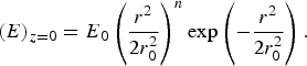 $$(E )_{z=0} = E_0 \left({\displaystyle{{r^2 } \over {2r_0 ^2 }}} \right)^n \exp \left({ - \displaystyle{{r^2 } \over {2r_0 ^2 }}} \right). $$
 Where, r 0 is the initial beam width, n is the order of the HGBs, and E 0 is the maximum amplitude of the laser beam around  $r=r_{\max }=r_0 \sqrt {2n}$. The modified electron density profile of the plasma due to ponderomotive force can be written as (Sodha et al., Reference Sodha, Ghatak and Tripathi1976)
 $$N_{0e}=N_0 \exp \left({ - \displaystyle{3 \over 4}{\rm \alpha} \displaystyle{{m_e } \over {m_i }}E.E^\cdot } \right). $$
 Where,  ${\rm \alpha}=\displaystyle{{e^2\, m_e } / {6k_B T_0 {\rm \gamma} m_e^2 {\rm \omega} _0^2 }}$ is nonlinearity parameter, N 0 is the density of plasma electrons in the absence of laser beam, k B is the Boltzmann's constant, T 0 is the equilibrium plasma temperature and γ is the ratio of the specific heats.
Consider the solution of Eq. (1) is
 $$E_0 \left({r\comma \; z} \right)=\hat iA\left({r\comma \; z} \right)\exp \left({ - ik_0 z} \right)\comma \; $$
Where A(r,z) is the complex amplitude of the wave. From Eqs. (1) and (6) we get,
 $$2ik\displaystyle{{\partial A} \over {\partial z}}=\left({\displaystyle{{\partial ^2 A} \over {\partial r^2 }}+\displaystyle{1 \over r}\displaystyle{{\partial A} \over {\partial r}}} \right)+\displaystyle{{{\rm \omega} _0^2 } \over {c^2 }}\left({{\rm \varepsilon} - {\rm \varepsilon} _0 } \right)A. $$
The complex amplitude A(r,z) can be represented as
 $$A\left({r\comma \; z} \right)=A_0 \left({r\comma \; z} \right)\exp \left\{{ - ik_0 S_0 \left({r\comma \; z} \right)} \right\}. $$
Now transform the (r, z) coordinate in to (η, z) coordinate as
 $${\rm \eta}=\left({\displaystyle{r \over {r_0 \,f_0 }} - \sqrt {2n} } \right). $$
 Where, r 0f 0 is the beam width of laser beam and maximum irradiance at  $r=r_0 \,f_0 \sqrt {2n}$. For paraxial ray approximation
  ${\rm \eta} \ll \sqrt {2n}$ and A0 is defined as
 $$A_0 ^2=\displaystyle{{E_0 ^2 } \over {2^{2n} f_0 ^2 }}\left({\sqrt {2n}+{\rm \eta} } \right)^{4n} \exp \left\{{ - \left({\sqrt {2n}+{\rm \eta} } \right)^2 } \right\}\comma \; $$
and eikonal of the pump beam is given as
 $$S_0 \left({{\rm \eta}\comma \; z} \right)=\displaystyle{{\left({\sqrt {2n}+{\rm \eta} } \right)^2 r_0 ^2 \,f_0 } \over 2}\displaystyle{{df_0 } \over {dz}}+{\rm \phi} \left(z \right). $$
 The dimensionless beam width parameter f 0 can be obtained by using the boundary conditions  $f_0 \vert _{z=0}=1$ and
  ${{df_0 } / {dz\vert _{z=0}}}=0$ (Akhmanov et al., Reference Akhmanov, Sukhorukov and Khokhlov1968)
 $${\rm \varepsilon} _0 \,f_0 \displaystyle{{d^2 f_0 } \over {d{\rm \xi} ^2 }}=\displaystyle{4 \over {\,f_0 ^2 }} - {\rm \varepsilon} _2 {\rm \rho} _0 ^2. $$
 Where  ${\rm \xi}=\displaystyle{c \over {r_0 ^2 {\rm \omega} _0 }}z$ is dimensionless parameter and
  ${\rm \rho} _0 ^2=\displaystyle{{r_0 ^2 {\rm \omega} _0 ^2 } \over {c^2 }}$. In the presence of ponderomotive force, the plasma density varies through the plasma channel and the dielectric function ɛ(η z) may be expressed as
 $$\eqalign{{\rm \varepsilon} \left({{\rm \eta}\comma \; z} \right) & =1 - \displaystyle{{{\rm \omega} _p ^2 } \over {{\rm \omega} _0 ^2 }}\exp \left\{{ - \displaystyle{3 \over 4}{\rm \alpha} \displaystyle{{m_e } \over {m_i }}\displaystyle{{{\rm E}_0^2 } \over {\,f_0^2 }}\left({\displaystyle{{\left({{\rm \eta}+\sqrt {2n} } \right)^2 } \over 2}} \right)^{2n}} \right. \cr & \quad\times\left. \vphantom{\left({\displaystyle{{\left({{\rm \eta}+\sqrt {2n} } \right)^2 } \over 2}} \right)^{2n}}{ \exp \left\{{ - \left({{\rm \eta}+\sqrt {2n} } \right)^2 } \right\}} \right\},} \; $$
and
 $${\rm \varepsilon} _0 \left(z \right)=1 - \displaystyle{{{\rm \omega} _p ^2 } \over {{\rm \omega} _0 ^2 }}\left\{{\exp \left({ - \displaystyle{3 \over 4}{\rm \alpha} \displaystyle{{m_e } \over {m_i }}\displaystyle{{E_0 ^2 } \over {\,f_0 ^2 }}n^{2n} e^{ - 2n} } \right)} \right\}\comma \; $$
 $${\rm \varepsilon} _2 \left(z \right)=2\left({\displaystyle{{{\rm \omega} _p ^2 } \over {{\rm \omega} _0 ^2 }}\displaystyle{3 \over 4}{\rm \alpha} \displaystyle{{m_e } \over {m_i }}\displaystyle{{E_0 ^2 } \over {\,f_0 ^2 }}n^{2n} e^{ - 2n} } \right)\exp \left({ - \displaystyle{3 \over 4}{\rm \alpha} \displaystyle{{m_e } \over {m_i }}\displaystyle{{E_0 ^2 } \over {\,f_0 ^2 }}n^{2n} e^{ - 2n} } \right). $$
Electron plasma wave (EPW) is excited in the presence of HGBs. For analysis of EPW in the presence of ponderomotive nonlinearity and filamented laser beam, the following equations are used.
The equation of motion can be written as
 $$m_e \left[{\displaystyle{{\partial V} \over {\partial t}}+\left({V.\nabla } \right)V} \right]=- eE - \displaystyle{e \over c}\left({V \times B} \right)- 2\Gamma _e m_e V - \displaystyle{{{\rm \gamma} k_B T_0 } \over N}\nabla N. $$
 Where 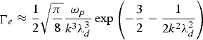 $\mathop \Gamma \nolimits_e \approx \displaystyle{1 \over 2}\sqrt {\displaystyle{{\rm \pi} \over 8}} \displaystyle{{{\rm \omega} _p } \over {k^3 {\rm \lambda} _d^3 }}\exp \left({ - \displaystyle{3 \over 2} - \displaystyle{1 \over {2k^2 {\rm \lambda} _d^2 }}} \right)$ is the Landau damping factor, V is the electron fluid velocity, N is the instantaneous electron density, E and B are associated with electric and magnetic field vectors, and
 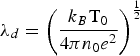 ${\rm \lambda} _d=\left({\displaystyle{{k_B {\rm T}_0 } \over {4{\rm \pi} n_0 e^2 }}} \right)^{{1 \over 2}}$ is the Debye length and k is the wave vector of the electrostatic wave. The continuity equation can be written as
 $$\displaystyle{{\partial N} \over {\partial t}}+\nabla .\left({NV} \right)=0. $$
From the Poisson's equation, one can get
 $$\nabla .E=- 4{\rm \pi} eN. $$
Applying the perturbation approximation,
N = N 0e + n e0 and V = V 0 + v; where n e0 ≪ N 0e & v ≪ V 0.
Solving Eqs. (16), (17), and (18), one obtains the general equation, which governs the electron density variation
 $$\displaystyle{{\partial ^2 n_{e0} } \over {\partial t^2 }}+2\mathop \Gamma \nolimits_e \displaystyle{{\partial n_{e0} } \over {\partial t}} - {\rm \gamma} v_{th}^2 \nabla ^2 n_{e0}+{\rm \omega} _p^2 \exp \left({ - \displaystyle{3 \over 4}{\rm \alpha} \displaystyle{{m_e } \over {m_i }}EE^ \ast } \right)n_{e0} \simeq 0. $$
Where, vth is the electron thermal speed. Consider a plane wave solution of Eq. (19),
 $$n_{e0} = n_{e00} \left({r\comma \; z} \right)\exp \left\{{i\left({{\rm \omega} t - kz - S\left({r\comma \; z} \right)} \right)} \right\}. $$
Where, ω and k are frequency and wave vector of the plasma wave and satisfy the Bohm-Gross dispersion relation
 $${\rm \omega} ^2={\rm \omega} _p^2 \displaystyle{{N_{0e} } \over {N_0 }}+{\rm \gamma} k^2 v_{th}^2. $$
Using the value of n e0 from Eq. (20) into Eq. (21) and separating the real and imaginary part, one gets
 $$\eqalign{2\displaystyle{{\partial S} \over {\partial z}}+\left({\displaystyle{{\partial S} \over {\partial r}}} \right)^2 & =\displaystyle{1 \over {k^2 n_{e00} }}\left[{\displaystyle{1 \over r}\left({\displaystyle{{\partial n_{e00} } \over {\partial r}}} \right)+\displaystyle{{\partial ^2 n_{e00} } \over {\partial r^2 }}} \right]\cr &+\displaystyle{{{\rm \omega} _p^2 } \over {{\rm \gamma} k^2 v_{th}^2 }}\left({1 - \displaystyle{{N_{0e} } \over {N_0 }}} \right)\comma} \; $$
 $$\eqalign{&2\displaystyle{{\partial n_{e00}^2 } \over {\partial z}}+\displaystyle{{\partial S} \over {\partial r}}\left({\displaystyle{{\partial n_{e00}^2 } \over {\partial r}}} \right)+n_{e00}^2 \displaystyle{1 \over {k^2 }}\left[{\displaystyle{1 \over r}\left({\displaystyle{{\partial S} \over {\partial r}}} \right)+\displaystyle{{\partial ^2 S} \over {\partial r^2 }}} \right] +\displaystyle{{2\Gamma _e } \over {3v_{th}^2 }}\displaystyle{{{\rm \omega} n_{e00}^2 } \over k}=0}. $$
Now transform the (r, z) coordinate in to (η, z) coordinate by using the Eq. (9). Hence Eqs. (22) and (23) can be solved in paraxial ray approximation and the solution is (for initial HGB distribution)
 $$\eqalign{n_{e00}^2 & =\displaystyle{{N_{e00}^2 } \over {\,f_e^2 2^{2n} }}\left({{\rm \eta}+\sqrt {2n} } \right)^{4n} \left({\displaystyle{{r_0 \,f_0 } \over {af_e }}} \right)^{4n} \exp \left({ - \left({{\rm \eta}+\sqrt {2n} } \right)^2} - 2k_i z \right).} $$
Where, f e and a are the dimensionless beam width parameter and radius of EPW, respectively. The eikonal of the electron plasma wave is described by,
 $$S=\left({{\rm \eta}+\sqrt {2n} } \right)^2 \displaystyle{{r_0^2 \,f_0^2 } \over {2f_e }}\displaystyle{{\partial f_e } \over {\partial z}}+{\rm \phi} \left(z \right). $$
To solve the Eqs. (22), (24), and (25), we have used the boundary condition at z = 0, f e = 1 & ∂f e/∂z = 0; and equating the power of η2, one gets
 $$\displaystyle{{\partial ^2 f_e } \over {\partial {\rm \xi} ^2 }}=\displaystyle{{\,f_e {\rm \rho} _0^2 } \over {\,f_0^2 }} \left[\matrix{\displaystyle{1 \over {k^2 r_0^2 f_0^2 }}\left\{{3+\left({\displaystyle{{r_0 f_0 } \over {af_e }}} \right)^4 } \right\}- 2\displaystyle{{{\rm \omega} _p^2 } \over {{\rm \gamma} k^2 v_{th}^2 }} \hfill \cr \times \left\{{\displaystyle{3 \over 4}{\rm \alpha} \displaystyle{{m_e } \over {m_i }}\displaystyle{{E_0^2 } \over {\,f_0^2 }}\exp \left({ - 2n} \right)n^{2n} } \right\}\cr \qquad\exp \left\{{ - \displaystyle{3 \over 4}{\rm \alpha} \displaystyle{{m_e } \over {m_i }}\displaystyle{{E_0^2 } \over {\,f_0^2 }}\exp \left({ - 2n} \right)n^{2n} } \right\}\hfill} \right]. $$
 Where,  $k_i=\displaystyle{{\Gamma _e {\rm \omega} } \over {kv_{th}^2 }}$ is the damping factor.
3. STIMULATED RAMAN SCATTERING
Consider the high frequency electric field ET which is the sum of the electric field of scattered wave ES and the electric field of pump laser beam E i.
 $${\rm E}_{\rm H}={\rm E}_i e^{i{\rm \omega} _0 t}+{\rm E}_S e^{i{\rm \omega} _s t} $$
Where, ω0 and ωS are the incident laser beam and scattered wave frequency, respectively. The wave equation for the scattered field can be written as
 $$\nabla ^2 E_s - \displaystyle{{{\rm \omega} _s ^2 } \over {c^2 }}\left({1 - \displaystyle{{{\rm \omega} _p ^2 } \over {{\rm \omega} _s ^2 }}\displaystyle{{N_{0e} } \over {N_0 }}} \right)E_s=\displaystyle{{{\rm \omega} _p ^2 } \over {2c^2 }}\displaystyle{{{\rm \omega} _s } \over {{\rm \omega} _0 }}\displaystyle{{n^{\ast }} \over {N_0 }}E_i. $$
The solution of Eq. (28) can be written as
 $$E_s=E_{s0} \left({r\comma \; z} \right)e^{ik_{s0} z}+E_{s1} \left({r\comma \; z} \right)e^{ - ik_{s1} z}. $$
 Where,  $k_{s0}=\displaystyle{{{\rm \omega} _s ^2 } \over {c^2 }}{\rm \varepsilon} _s \left(0 \right)$, k S1 and ωS satisfy the phase matching condition.
 $$k_{S1}=k_0 - k\comma \; {\rm \omega} _S={\rm \omega} _0 - {\rm \omega}. $$
From Eqs. (28) and (29), one gets
 $$\eqalign{&\left({\displaystyle{1 \over r}\displaystyle{{\partial {\rm E}_{S0} } \over {\partial r}}+\displaystyle{{\partial ^2 {\rm E}_{S0} } \over {\partial r^2 }}} \right)+2ik_{S0} \displaystyle{{\partial {\rm E}_{S0} } \over {\partial z}} - k_{S0}^2 {\rm E}_{S0} +\displaystyle{{{\rm \omega} _S^2 } \over {c^2 }} \in _S \left({r\comma \; z} \right){\rm E}_{S0}=0\comma \; } $$
 $$\eqalign{&\left({\displaystyle{1 \over r}\displaystyle{{\partial {\rm E}_{S1} } \over {\partial r}}+\displaystyle{{\partial ^2 {\rm E}_{S1} } \over {\partial r^2 }}} \right)- 2ik_{S1} \displaystyle{{\partial {\rm E}_{S1} } \over {\partial z}} - k_{S0}^2 {\rm E}_{S1} \cr &\quad +\displaystyle{{{\rm \omega} _S^2 } \over {c^2 }} \in _S \left({r\comma \; z} \right){\rm E}_{S1}=\displaystyle{1 \over 2}\displaystyle{{{\rm \omega} _p^2 } \over {c^2 }}\displaystyle{{{\rm \omega} _S } \over {{\rm \omega} _0 }}\displaystyle{{n^ {\ast }} \over {N_0 }}{\rm E}_0 e^{ - ik_0 S_0 }.} $$
 Where,  ${\rm \varepsilon} _S \left({r\comma \; z} \right)=1 - \displaystyle{{{\rm \omega} _p^2 } \over {{\rm \omega} _S^2 }}\left({\displaystyle{{N_{0e} } \over {N_0 }}} \right)$.
To simplify the Eq. (31), one can substitute ES0 = ES00(r,z) $e^{ik_{s0^S_{}c}}$ in Eq. (31) and separating the real and imaginary part, one can get
 $$\eqalign{&2\left({\displaystyle{{\partial S_c } \over {\partial z}}} \right)+\left({\displaystyle{{\partial S_c } \over {\partial r}}} \right)^2=\displaystyle{1 \over {k_{s0} ^2 E_{s00} }}\left({\displaystyle{{\partial ^2 E_{s00} } \over {\partial r^2 }}+\displaystyle{1 \over r}\displaystyle{{\partial E_{r00} } \over {\partial r}}} \right)\cr & \quad+\displaystyle{{{\rm \omega} _S ^2 } \over {k_{S0}^2 c^2 }}\left\{{ \in _S - \in _S \left(0 \right)} \right\}\comma \; } $$
 $$\displaystyle{{\partial E_{s00} ^2 } \over {\partial z}}+E_{s00} ^2 \left({\displaystyle{{\partial ^2 S_c } \over {\partial r^2 }}+\displaystyle{1 \over r}\displaystyle{{\partial S_c } \over {\partial r}}} \right)+\left({\displaystyle{{\partial E_{s00} ^2 } \over {\partial r}}} \right)\left({\displaystyle{{\partial S_c } \over {\partial r}}} \right)=0. $$
Now transform the (r,z) coordinate in to (η, z) coordinate by using the Eq. (9) and the solution of the Eqs. (33) and (34) can be written as
 $$\eqalign{&E_{s00} ^2=\displaystyle{{B^{{\prime}2} } \over {2^{2n} f_s ^2 }}\left({\sqrt {2n}+{\rm \eta} } \right)^{4n} \left({\displaystyle{{r_0 f_0 } \over {bf_s }}} \right)^{4n} \exp \left\{{ - \displaystyle{{r_0^2 f_0^2 } \over {b^2 f_s^2 }}\left({\sqrt {2n}+{\rm \eta} } \right)^2 } \right\}\comma \; } $$
 $$S_c=\displaystyle{{\left({\sqrt {2n}+{\rm \eta} } \right)^2 } \over 2}\displaystyle{{r_0^2 f_0^2 } \over {\,f_s }}\displaystyle{{\partial f_s } \over {\partial z}}+{\rm \phi} _s \left(z \right). $$
 For an initial plane wave front, we used the boundary conditions f S = 1,  $\displaystyle{{\partial f_S } \over {\partial z}}=0$ at z = 0. Using Eqs. (35) and (36) in Eq. (33) and equating the coefficient of η2, one gets
 $$\displaystyle{{d^2 f_s } \over {d{\rm \xi} ^2 }}=\displaystyle{{\,f_s {\rm \rho} _0^2 } \over {\,f_0^2 }}\left\{{\displaystyle{1 \over {k_{S0}^2 r_0^2 f_0^2 }}\left\{{3+\left({\displaystyle{{r_0 f_0 } \over {bf_s }}} \right)^4 } \right\}- \displaystyle{{{\rm \omega} _s^2 } \over {k_{s0}^2 c^2 }} \in _{S2} } \right\}. $$
In the presence of ponderomotive nonlinearity the ɛS(η, z) can be expressed as
 $${\rm \varepsilon} _S \left({{\rm \eta}\comma \; z} \right)={\rm \varepsilon} _S \left(0 \right)- {\rm \eta} ^2 {\rm \varepsilon} _{S2}. $$
Where
 $${\rm \varepsilon} _S \left(0 \right)=1 - \displaystyle{{{\rm \omega} _p^2 } \over {{\rm \omega} _S^2 }}\left\{{\exp \left({ - \displaystyle{3 \over 4}{\rm \alpha} \displaystyle{{m_e } \over {m_i }}\displaystyle{{E_0 ^2 } \over {\,f_0 ^2 }}n^{2n} e^{ - 2n} } \right)} \right\}\comma \; $$
 $${\rm \varepsilon} _{S2}=2\displaystyle{{{\rm \omega} _p^2 } \over {{\rm \omega} _S^2 }}\left\{{\displaystyle{3 \over 4}{\rm \alpha} \displaystyle{{m_e } \over {m_i }}\displaystyle{{E_0 ^2 } \over {\,f_0 ^2 }}n^{2n} e^{ - 2n} \exp \left({ - \displaystyle{3 \over 4}{\rm \alpha} \displaystyle{{m_e } \over {m_i }}\displaystyle{{E_0 ^2 } \over {\,f_0 ^2 }}n^{2n} e^{ - 2n} } \right)} \right\}. $$
The value of B′ may be obtained on applying appropriate boundary conditions
 $${\rm E}_S={\rm E}_{S0} \left({r\comma \; z} \right)e^{ik_{S0} z}+{\rm E}_{S1} \left({r\comma \; z} \right)e^{ - ik_{S1} z}=0\ {\rm at}\ z=z_c.$$
Where, z c = L − z and L is the interaction length. Here, z c is chosen sufficiently large so that n e00 is nearly zero. Therefore, at z = z c, one gets
 $$\eqalign{& {\rm B}^{\prime}=\displaystyle{1 \over {2^{n+1} }}\left({\displaystyle{{{\rm \omega} _p^2 } \over {c^2 }}} \right)\left({\displaystyle{{n_0 } \over {N_0 }}} \right)\left({\displaystyle{{{\rm \omega} _s } \over {{\rm \omega} _0 }}} \right)\displaystyle{{\,f_s \left({z_c } \right)} \over {\,f_e \left({z_c } \right)f_s \left({z_c } \right)}}\left({\displaystyle{r \over {af_e \left({z_c } \right)}}} \right)^{2n} \cr & \qquad\times \left({\displaystyle{r \over {r_0 f_0 \left({z_c } \right)}}} \right)^{2n} \left({\displaystyle{{bf_s \left({z_c } \right)} \over r}} \right)^{2n} \cr & \qquad\displaystyle{{{\rm E}_{00} e^{ - ik_i z_c } } \over {\left\{{k_{s1}^2 - k_{s0}^2 - \displaystyle{{{\rm \omega} _p^2 } \over {c^2 }}\left({1 - \displaystyle{{N_{0e} } \over {N_0 }}} \right)} \right\}}}\displaystyle{{e^{ - i\left({k_0 S_0\,+\,k_{S0} S_c } \right)} } \over {e^{i\left({k_{S0} z_c\,+\,k_{S1} z_c } \right)} }}.} $$
With the condition
 $$\displaystyle{1 \over {a^2 f_e^2 \left({z_c } \right)}}+\displaystyle{1 \over {r_0 ^2 f_0^2 \left({z_c } \right)}}=\displaystyle{1 \over {b^2 f_s^2 \left({z_c } \right)}}. $$
Back reflectivity is defined as the ratio of back scattered power to the incident power, and is given by
 $$\eqalign{& R \simeq \displaystyle{1 \over 4}\left({\displaystyle{{{\rm \omega} _p ^2 } \over {c^2 }}} \right)^2 \left({\displaystyle{{n_0 } \over {N_0 }}} \right)^2 \left({\displaystyle{{{\rm \omega} _s } \over {{\rm \omega} _0 }}} \right)^2 \displaystyle{1 \over {\left\{{k_{s1} ^2 - k_{s0} ^2 - \displaystyle{{{\rm \omega} _p ^2 } \over {c^2 }}\left({1 - \displaystyle{{N_{0e} } \over {N_0 }}} \right)} \right\}^2 }} \cr & \qquad\times \left({\displaystyle{{r_0 f_0 } \over {af_e }}} \right)^{4n} \displaystyle{{\left({{\rm \eta}+\sqrt {2n} } \right)^{8n} } \over {2^{4n} f_e^2 f_0^2 }} \cr & \qquad\exp \left\{{ - \left({{\rm \eta}+\sqrt {2n} } \right)^2 \displaystyle{{r_0^2 f_0^2 } \over {a^2 f_e^2 }} - \left({{\rm \eta}+\sqrt {2n} } \right)^2 - 2k_i z} \right\}.} $$
4. RESULT AND DISCUSSION
In collisionless plasma, the density of the plasma varies due to the ponderomotive force and the refractive index increases at the position of maximum irradiance; and the laser gets focused in the plasmas. Eqs. (9) and (10) describe the intensity profile of HGBs in plasma along the radial direction in the presence of ponderomotive nonlinearity. The intensity profile of the laser beam depends on the beam width f 0 in the paraxial regime; and Eq. (12) determines the focusing/defocusing of laser beam along the distance of propagation in plasma. In Eq. (12), on the right-hand side, the first term is responsible for diffraction, while the second term is responsible for the converging behavior of the beam during propagation in plasma. Numerical evaluation of Eqs. (9) and (12) are performed by using the typical laser beam parameters: the vacuum wavelength of the laser beam (λ = 1064 nm), laser power flux (1018W/cm2), the initial radius of the laser beam r 0 = 10 µm, the initial radius of the EPW a = 10 μm, plasma density n/n cr = 0.2 and electron thermal speed v th = 0.1c. Eq. (12) has been solved for an initial plane wave front of the hollow Gaussian beam and the numerical results are presented in the form of Figures 1, 2, and 3. The variation of intensity for the EPW on the order 1, 2, and 3 have been shown in Figures 1a, 2a, and 3a, respectively at ξ = 0; while in Figures 1b, 2b, and 3b at first focal point (beam focused position) with normalized distance ξ. It is obvious from the figure that in paraxial regime the intensity of laser beam is maximum at η = 0; and at first focal point the intensity of laser beam decreases with increase in the order of the HGBs.

Fig. 1. (Color online) Normalized intensity distribution for order 1. (a) HGB and EPW at ξ = 0, (b) HGB at first focal point, (c) EPW at first focal point, (d) Back SRS at first focal point.
Fig. 2. (Color online) Normalized intensity distribution for order 2. (a) HGB and EPW at ξ = 0, (b) HGB at first focal point, (c) EPW at first focal point, (d) Back SRS at first focal point.
Fig. 3. (Color online) Normalized intensity distribution for order 3. (a) HGB and EPW at ξ = 0, (b) HGB at first focal point, (c) EPW at first focal point, (d) Back SRS at first focal point.
When the high power HGBs propagates through plasma, the motion of electron will be modified due to ponderomotive nonlinearity and will give rise to change in the nonlinear current density. The density profile of plasma is modified and governed by the Eq. (24). The intensity profile of the EPW depends on the beam width parameter f e in the paraxial regime. We have solved Eq. (26) numerically to obtain the amplitude of the density perturbation at finite z. The results are displayed in Figures 1a, 2a, and 3a, which show that the EPW gets excited due to nonlinear coupling with high power laser beam in the presence of ponderomotive nonlinearity and similar kind of result observed by Mendonca et al. (Reference Mendonca, Thide and Then2009) without introducing the nonlinearity term. The EPW is also having the maximum intensity (for different order of HGBs) at η = 0 in the paraxial regime. Figures 1c, 2c, and 3c depicts that the variation in intensity for order 1, 2, and 3 of EPWs at first focal point, with normalized distance ξ, respectively.
Eq. (37) expresses the beam width parameter of the scattered beam and Eq. (43) gives the reflectivity against the distance of propagation. The result displayed in Figures 1d, 2d, and 3d shows the normalized intensity of the back reflected laser beam at the focal point for order 1, 2, and 3, respectively. We have solved Eq. (43) numerically and the results are presented in the form of Figure 4, which shows the variation of the back reflectivity with normalized distance for different order of HGBs around the maximum irradiance η = 0. In Figure 4, the back reflectivity for different order of HGBs are presented with normalized distance ξ and is maximum at the focal points of the focused laser beam. It is also shown that as we increase the order of the HGBs the reflectivity decreases because the focusing of HGBs decreases with increasing order of the beam.
Fig. 4. (Color online) Variation of back reflectivity against normalized distance of propagation ξ.
5. CONCLUSION
For deeper understanding in laser plasma interaction, higher modes of laser beam are also important because the total field is superposition of all the modes in cylindrical coordinates. The earlier work in laser plasma interaction is limited to TEM00 mode which has maximum intensity at the center but in the presence of higher modes, intensity profile should be modified. In the present article, we studied the excitation of EPW in the presence of laser beam which has null intensity at the center. The focusing of the HGBs, excitation of EPW and back reflectivity of HGBs has been investigated. These results should find applications in the laser induced fusion scheme where higher modes are also present in the laser beam.
ACKNOWLEDGMENT
This work was partially supported by Department of Science and Technology (DST), India and University Grant Commission (UGC), India.

