NOMENCLATURE
- CD
drag coefficient
- CL
lift coefficient
- CM
pitching moment coefficient
- LE
leading-edge
- LEX
leading-edge extension
- MAC
mean aerodynamic chord
- Re
Reynolds number
- V
free stream velocity
- α
angle-of-attack
- ρ
air density
1.0 INTRODUCTION
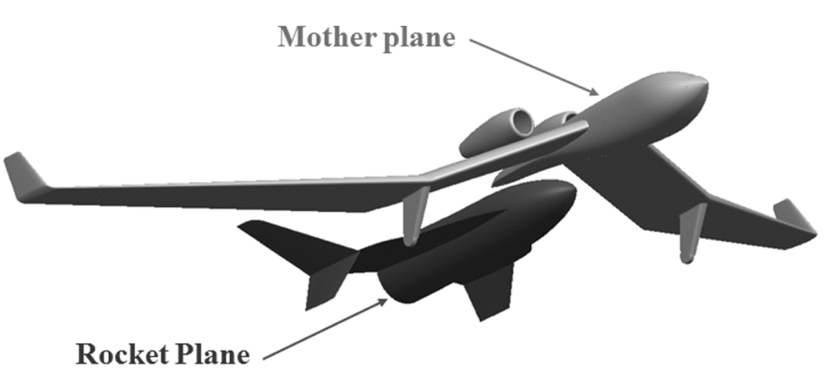
The article presents wind tunnel tests of the Rocket Plane in the tailless configuration. The Rocket Plane is part of a Modular Airplane System (MAS)(Reference Galiński, Goetzendorf-Grabowski, Mieszalski and Stefanek1,Reference Figat, Galiński and Kwiek2) for space tourism application (see Fig. 1). The concept is based on the assumption that the mother aircraft and the Rocket Plane are designed as tailless aircraft, but during the joined flight phase, they form a conventional airplane where the Rocket Plane will be used as a tail of MAS. Moreover, the Rocket Plane is equipped with the Leading Edge Extension (LEX)(Reference Luckring3). It generates a vortex lift(Reference Luckring3–Reference Lamar5) which increases in the lift for high angles-of-attack and in turn reduces a rate of descent. According to the initial analysis of the Rocket Plane return flight, the Mach number should be smaller than Ma = 3.5. The lift vortex needs a sharp leading edge (LE). On the other hand the initial re-entry speed of the vehicle should be small; therefore, the problem of structure overheating should not occur. An example of an aircraft which was designed with a sharp LE and was performing long flights at Ma = 3 was Lockheed SR-71; the problem of excessive material consumption on LE was not observed(Reference Goodall and Miller6).

Figure 1. The concept of MAS.
The Rocket Plane mission profile includes wide range of flight speeds, angles-of-attack and extreme atmospheric conditions. The main goal of research was to evaluate the impact of the LEX and wing tip plates on aerodynamic characteristics of the vehicle in tailless configuration. Only the low flight speed regime was considered but the wide range of angles-of-attack was included. It allows one to assess the correctness of the project assumptions like geometry of the LEX and wing tip plates. The Rocket Plane usually flies with transonic and supersonic speeds, but a separation process form the mother plane and landing is performed with subsonic speed; therefore, the first stage of this project was research into the subsonic flight regime. Moreover, presented results could be very useful for the design of vehicles in tailless configuration which fly in standard atmosphere conditions.
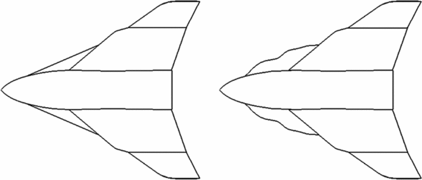
The test was carried out for two concepts of the LEX shape. The first one was simple straight LEX (configuration 1111) presented in Fig. 2 and Table 1. The second one has more sophisticated shape (configuration 1211), and its geometry was a result of the numerical optimisation process(Reference Figat, Kwiek and Seneńko7).

Figure 2. Two considered models – configuration 1111 on the left and configuration 1211 on the right.
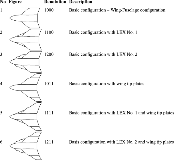
Table 1 Denotation of all considered models

The schedule of the wind-tunnel experiment consists of two sets of the test. Both of them included only longitudinal characteristics. At the beginning, the conceptual configuration (1111) was tested. After that, the final configuration (1211) was investigated. In both cases, the impact of the LEX and wing tip plates on the aerodynamic characteristics was analysed.
2.0 WIND-TUNNEL TEST
2.1 Experimental model
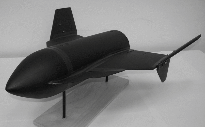
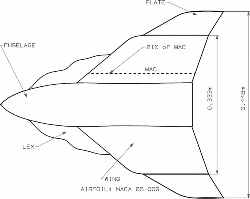
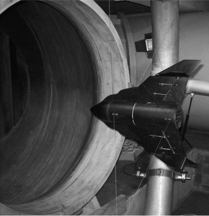
The Rocket Plane model for wind-tunnel tests was built in 1:15 scale. The model had a modular structure. The axis symmetric fuselage was a base of the model which was the same for all considered configurations. All of the other components, such as LEX and wing tip plates, were exchangeable and allowed for the testing of different configurations. Figs 3 and 4 present the experimental model (configuration 1211) and its main geometry parameters.

Figure 3. Experimental model of the Rocket Plane, configuration 1211.

Figure 4. Sketch of experimental model (configuration 1211) with the main dimension.
2.2 Wind tunnel
The wind-tunnel tests were carried out in a closed-circuit subsonic tunnel (1.16m) at Warsaw University of Technology (the Faculty of Power and Aeronautical Engineering). The Rocket Plane model was hanged at the open measure section by means of wires which passed through muffs in the fuselage (see Fig. 5). The tunnel is equipped with the Witoszyński-type balance(Reference Witoszyński8) with a digital data acquisition system. During the test, only a lift, drag and pitching moment were measured.

Figure 5. Experimental model of the Rocket Plane hanged in the wind tunnel (configuration 1211).
2.3 Test conditions and assumptions
The presented results were measured at a free stream velocity of 40 ms−1, which corresponds to a Reynolds number of about Re = 0.7*106 based on the MAC of the wing. The measurements were taken in aerodynamic coordinate systems for the same reference point, which was 21% of the wing MAC (Fig. 4). It was connected with the assumed centre-of-gravity position of the Rocket Plane. The longitudinal characteristics were measured for the range of angles-of-attack from −5° to +40°. Table 1 presents all tested configurations of the Rocket Plane which were used in wind tunnel tests.
Turbulence intensity in the wind tunnel was equal to 5%. It was measured by a constant temperature anemometer(Reference Grobelny9). The value of turbulence intensity was quite high, but the influence on the result was not critical due to the model length and vortex flow. The high value of turbulence intensity can only cause letter vortex breakdown.
As a result of the tests, the lift, drag and pitching moment coefficients were obtained. The reference area was changed according to the current configuration; the basic reference area was equal to the wing area. The reference area was changing due to the identified aerodynamic synergism effect(Reference Lamar and Frink10) of the Rocket Plane components. The change of area caused by adding the LEX No. 1 was equal to about 6%, and the LEX No. 2 was equal to about 12% of the basic area. Increase in the reference area caused by wing tip plates was equal to 40% of the basic area. The wing's span was the same for all examined models and was determined by the size of the mother plane.
During research in the wind tunnel, a lot of data were collected. The step between measured points was 0.5°. Results of the research were presented by the graphs which contain a line of polynomial approximation of measured data, however only selected measured points are included due to the clarity of diagrams.
2.4 Uncertainty analysis
Uncertainty analysis was prepared based on the aerodynamic coefficients(Reference Jaracz and Szefliński11). The aerodynamic coefficients depended on two measured parameters: the force and dynamic pressure, which uncertainty was 2.07% and 1%, respectively. The free stream velocity depended on dynamic pressure and air density. However the air density depended on the air pressure and temperature, in which the uncertainty was 0.1% and 2.86%, respectively. Finally, the air density and free stream velocity was ρ = 1.175 ± 0.02 (kg/m3) and V = 40 ± 0.40 (ms−1).
3.0 RESULTS
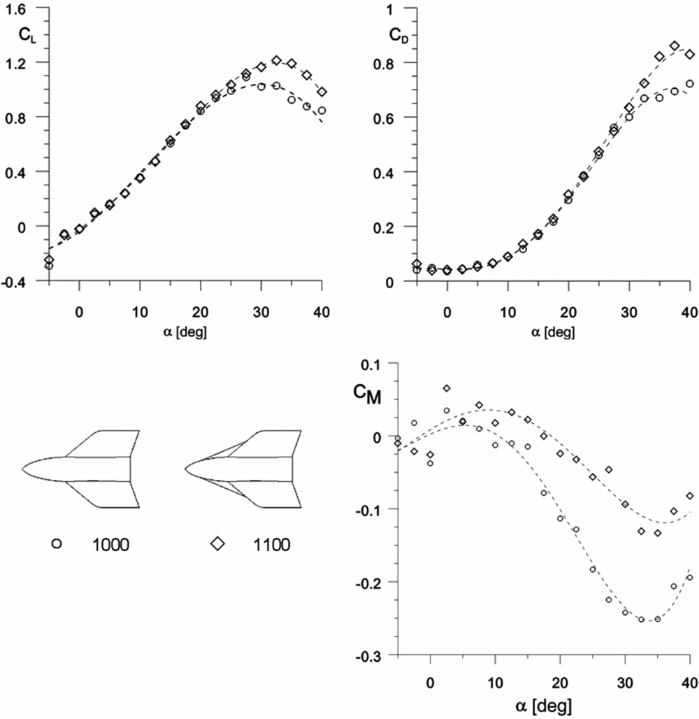
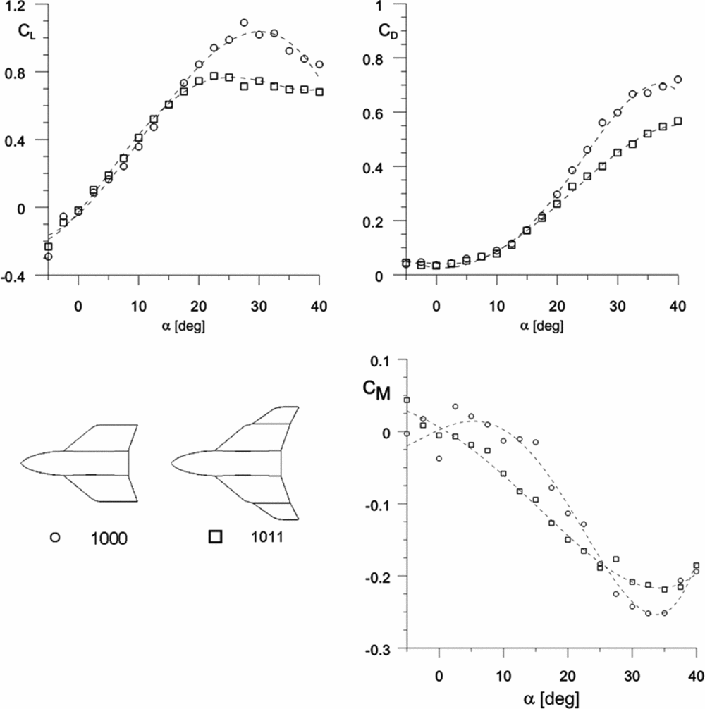
At the beginning, LEX No. 1 (see Table 1) and the wing tip plate's impact on the aerodynamics of the Rocket Plane in tailless configuration were investigated. First, the LEX No. 1’s impact on the aerodynamic coefficients for the basic configuration is presented in Fig. 6. A slight increase in the maximum lift coefficient was noticed. Also, the critical angle-of-attack was forward shifted. The drag coefficient increased due to the aforementioned higher lift-force at higher angles-of-attack. The static stability of the basic configuration with LEX No. 1 was not improved; however, the strength of the pitch-up effect was weaker (Fig. 6). It was mainly caused by the change in effective sweep angle of the LEX-wing configuration compared to the wing LE sweep angle. The effect is similar to the impact of delta wings’ LE sweep angles on the lift curve(Reference Bertin14,Reference Gursul, Gordnier and Visbal15) . The typical shape of the lift curve for high sweep angle was obtained for considered configurations.

Figure 6. LEX No. 1’s impact on the lift, drag and pitching moment coefficients of the basic configuration.
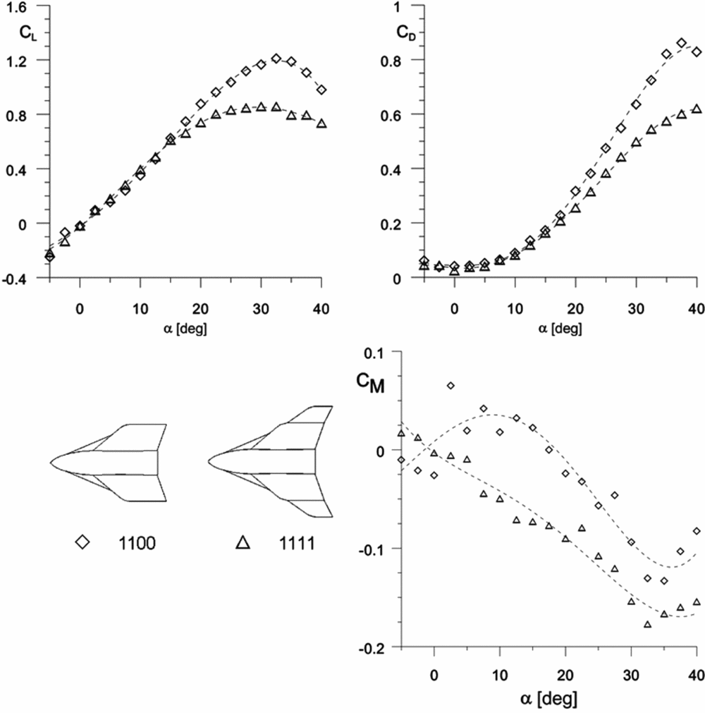
Adding the wing tip plates to the basic configuration with LEX No. 1 was next analysed. First of all, it increased the effective aspect ratio of the wing. It caused the significant reduction of the maximum lift coefficient and slightly changed the lift slope for low and medium angles-of-attack (Fig. 7). Moreover, change in the aspect ratio caused a decrease in the drag coefficient for higher angles-of-attack (above 15°). This is connected with lower values of an induce drag. The static stability of the complete Rocket Plane (configuration with LEX No. 1 and the wing tip plates) was improved for the whole range of angles-of-attack. However, the pitch-up(Reference Zhao, Kwak and Rinoie12) effect still occurred but had a weaker impact. If the obtained results were compared to results of research into delta wings(Reference Bertin14,Reference Gursul, Gordnier and Visbal15) , the same sort of similarity could be noticed. Adding the wing tip plates to the considered configuration is similar to the effect of decreasing the effective sweep angle of the delta wing.

Figure 7. Wing tip plates’ impact on the drag, lift and pitching moment coefficients of the basic configuration with LEX No. 1.
Next, the wing tip plates’ impact on the basic configuration (Table 1) was analysed (Fig. 8). Significant reduction of the maximum lift coefficient was obtained, and the slight change of the lift slope versus angle-of-attack was observed. Moreover, the wing tip plates’ significant impact on the static stability was noticed, especially at the low angles-of-attack. As was mentioned earlier, adding the wing tip plates’ increase in the effective aspect ratio of the wing caused the induced drag coefficient reduction.

Figure 8. Wing tip plates’ impact on the lift, drag and pitching moment coefficients of the basic configuration.
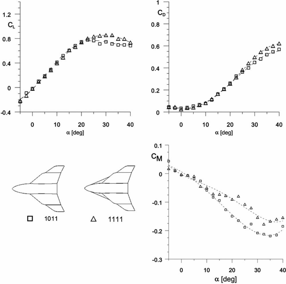
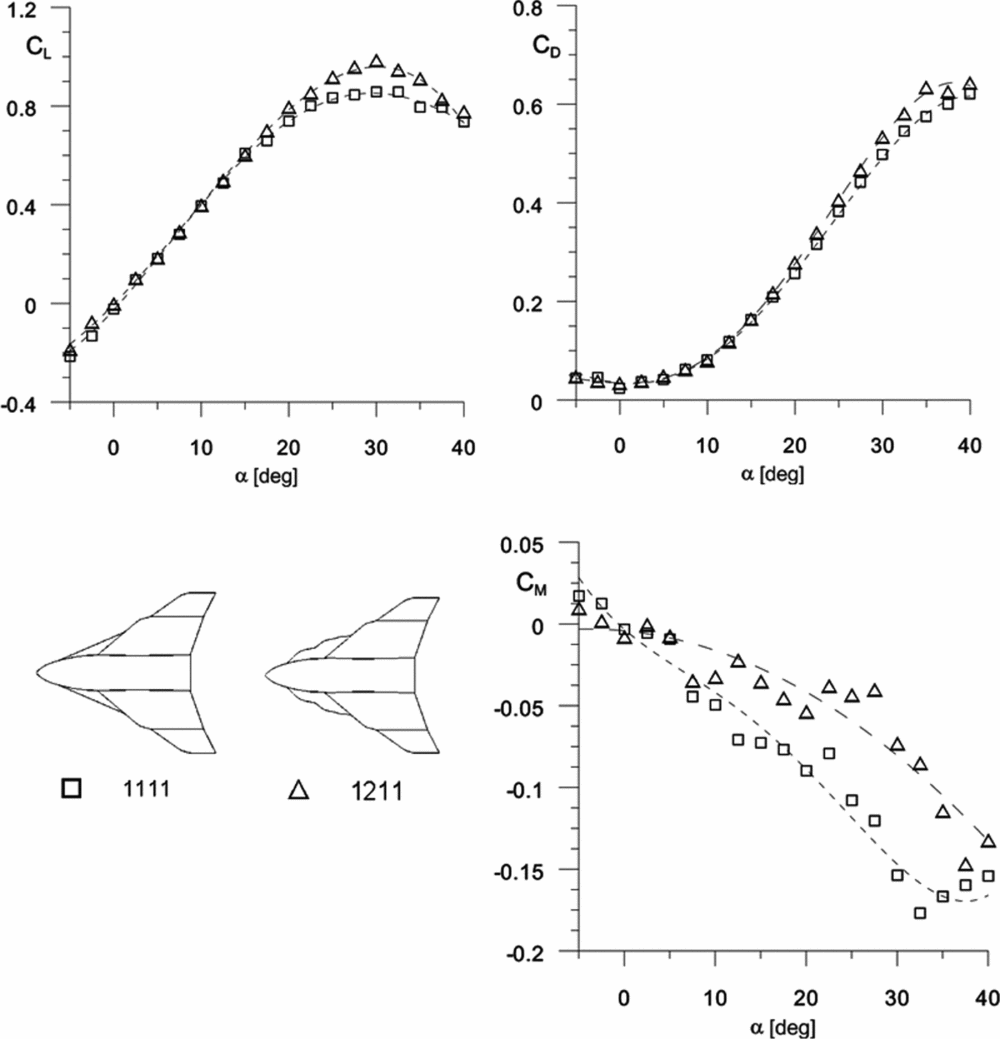
The last analysis presents the LEX No. 1’s impact on the aerodynamic characteristics of the basic configuration with wing tip plates (Fig. 9). The LEX No. 1 had a minor impact on the aerodynamic characteristics. The slight change in maximum lift and drag coefficients for high angle-of-attack were observed. Moreover, the minor static stability reduction of the Rocket Plane's complete configuration (see Table 1, conf.1111) was noticed.

Figure 9. LEX No. 1’s impact on the lift, drag and pitching moment coefficients of the basic configuration with the wing tip plates.
The final conclusions about results of tests for the presented Rocket Plane configuration with straight LEX (LEX No. 1) reveals the strong similarity to the results for delta wings with the high sweep angle. Adding the LEX No. 1 to the basic configuration increased the wing effective sweep angle and decreased the aspect ratio. It allowed the higher maximum lift coefficient to be obtained at the higher angle-of-attack, but the increase was relatively low. The wing tip plates’ impact on the Rocket Plane exhibited an opposite but more meaningful effect compared to the LEX. The LEX-wing aspect ratio increased, but the effective sweep angle reduced(Reference Gursul, Gordnier and Visbal15). That was the reason for reduction of the maximum lift and drag coefficients of considered configurations.
Moreover, wing tip plates had a crucial role on the stability of the Rocket Plane in tailless configuration. This effect was higher than instability influence of the LEX. However, it did not prevent the pitch-up problem which still occurred at high angles-of-attack.
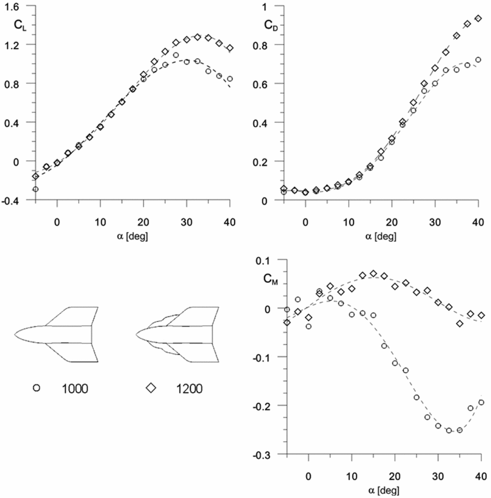
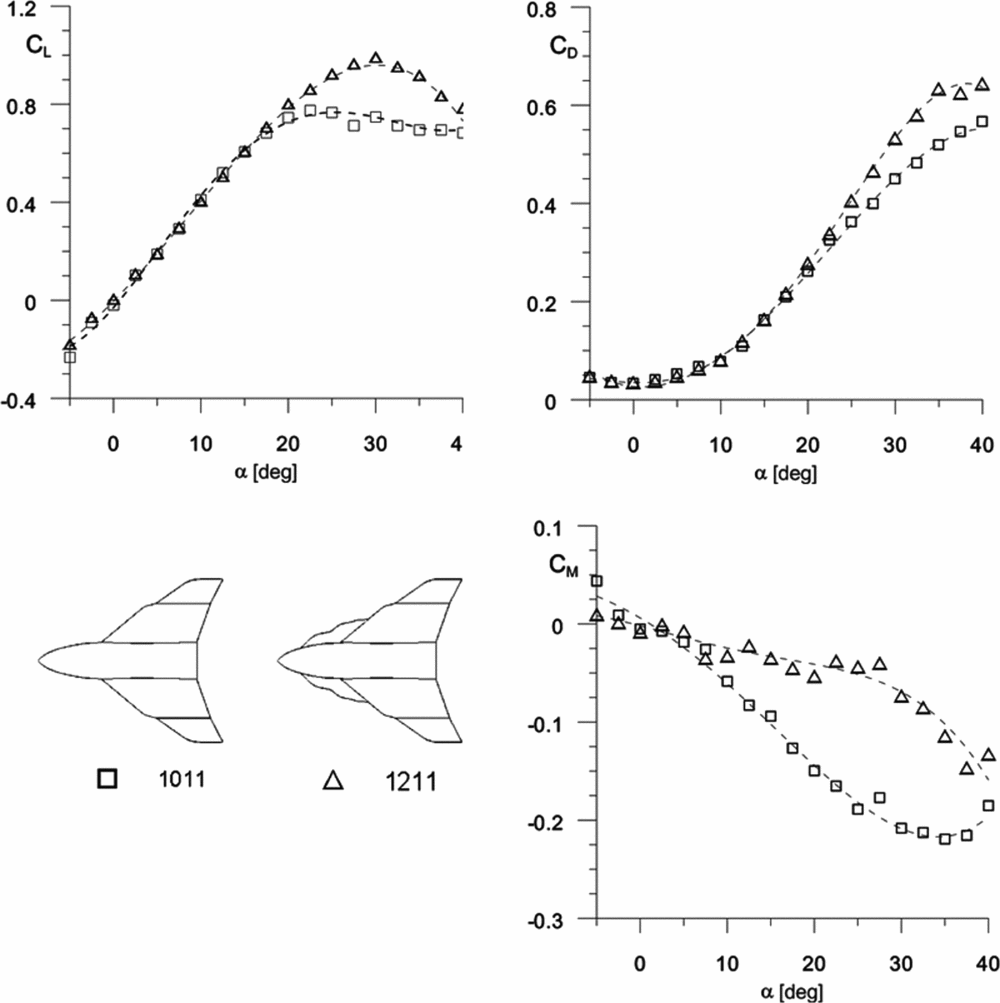
The second part of tests includes the analysis of the Rocket Plane with a specially designed new shape of the LEX (see LEX No. 2 in Table 1). As was mentioned in the previous section, the new LEX and wing tip plates’ (the wing tip plates were the same as in the configuration with LEX No. 1) impact on the aerodynamic characteristics was investigated. Figure 10 presents the LEX No. 2’s impact on the lift, drag and pitching moment coefficients of the basic configuration. The LEX No. 2 significantly improved the maximum lift coefficient but caused the basic configuration with LEX to be unstable for the low and medium angles-of-attack (up to the 15°). Moreover, a higher lift coefficient for high angles-of-attack caused the higher drag coefficient.

Figure 10. LEX No. 2’s impact on the lift, drag and pitching moment coefficients of the basic configuration.
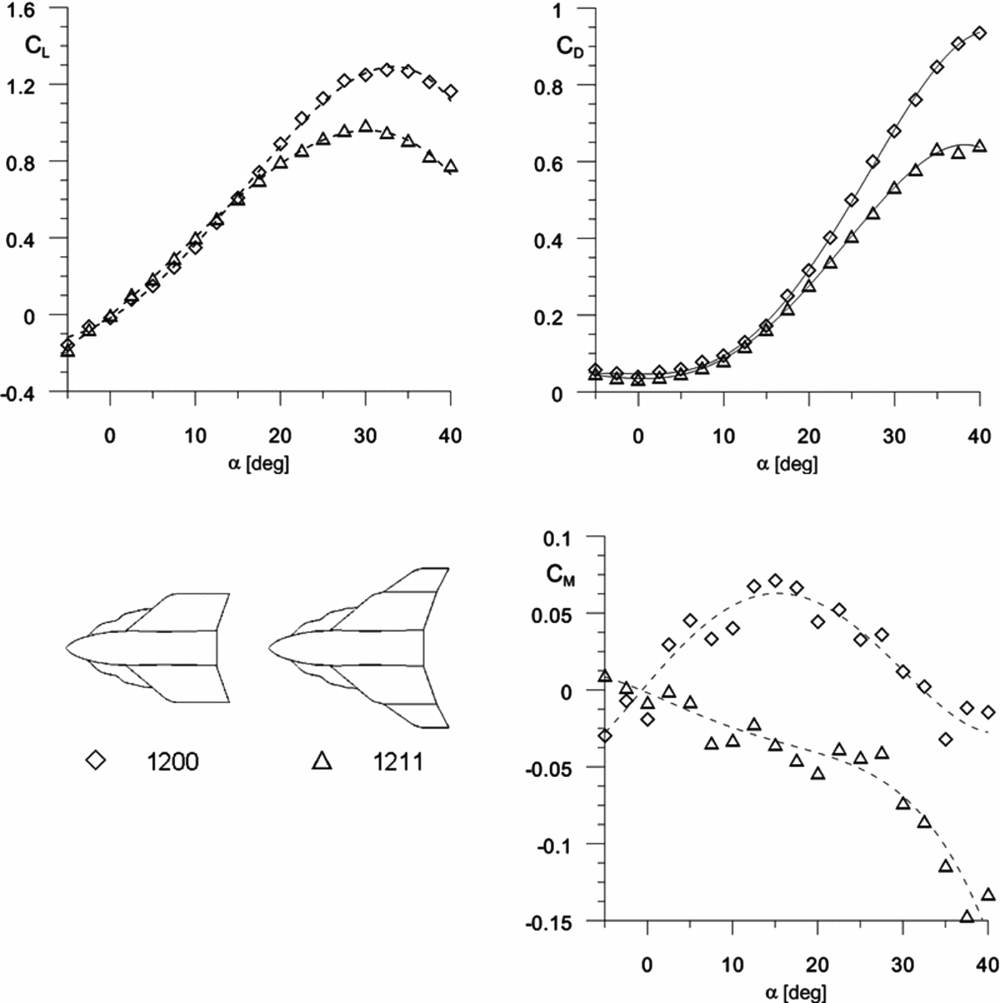
Next, the wing tip plates’ impact on the basic configuration with LEX No. 2 was analysed. Figure 11 presents its impact on the lift, drag and pitching moment coefficients. Decrease in the maximum lift coefficient and change in the lift slope for the analysed configuration was observed. Moreover, significant reduction of the drag caused by adding the wing tip plates was observed. The wing tip plates’ impact on aerodynamic characteristics was similar to the previous configuration with the straight LEX. The strong stability effect of the wing tip plate, again, was observed.

Figure 11. Wing tip plates’ impact on the lift, drag and pitching moment coefficients of basic configuration with the LEX No. 2.
The last analysis of test results includes the LEX No. 2’s impact on the lift, drag and pitching moment coefficients for the basic configuration with wing tip plates; the result is present in Fig. 12. The LEX No. 2’s effect on drag and lift coefficients is similar to the foregoing case with LEX No. 1. Slight reduction of the static stability of the configuration with LEX No. 2 was noticed; it was caused by using the more effective new LEX. However, the pitch-up problem was alleviated.

Figure 12. LEX No. 2’s impact on the lift, drag and pitching moment coefficients of the basic configuration with the wing tip plates.
The final conclusions from this part of the investigation (Rocket Plane with the LEX No. 2) reveal that the new more advanced LEX improved the lift coefficient but had a negative impact on the static stability. As was in the first configuration (1111), the wing tip plates had an important impact on the aerodynamic characteristics.
Finally, Fig. 13 presents the comparison of two complete models of the Rocket Plane with the LEX No. 1 (configuration 1111, see Table 1) and LEX No. 2 (configuration 1211, see Table 1). The lift, drag and pitching moment coefficients were presented in Fig. 13. Results, as was for the previous analysis, included only the aerodynamic synergism of analysed components. It means that in each case aerodynamic coefficients were referred to the different areas.

Figure 13. Comparison of two complete Rocket Planes (configurations 1211 and 1111).
Characteristics of the lift, drag and pitching moment coefficients for low angles-of-attack are similar. The significant impact of the vortex flow generated by the LEX No. 2 for angles-of-attack above 15° was observed. The new LEX provided higher values of the maximum lift coefficient and the stall angle-of-attack. Unfortunately, the higher lift coefficient caused the configuration to be less stable compared to the configuration with the straight LEX.
3.1 Oil visualisation
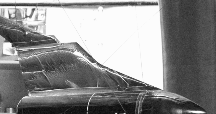
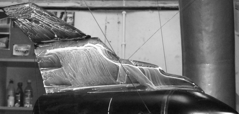
The last part of the wind tunnel experiment consisted of oil visualisation. This method of flow visualisation on the Rocket Plane surface was used mainly to check the position and the number of vortices generated by the LEX(Reference Anderson13,Reference Bertin14) . The oil visualisation was made for two complete configurations of the Rocket Plane only. Both cases were made for angle-of-attack, α = 28°. Figures 14 and 15 present the oil visualisation for configuration with the LEX Nos. 1 and 2, respectively.

Figure 14. Oil visualisation for configuration 1111.

Figure 15. Oil visualisation for configuration 1211.
The analysis of flow pattern revealed that for the configuration with the straight LEX, only the one vortex was generated on the leading edge of the LEX (Fig. 14). However, for configuration with the LEX No. 2, the two vortices were observed (Fig. 15). Further analysis of the flow visualisation revealed that, for high angles-of-attack, the upper plates generated an additional pair of vortices which increased the drag but did not generate the lift.
4.0 CONCLUSION
The main goal of the presented wind tunnel tests was to check two configurations of the Rocket Plane in tailless configuration. The mutual influence of the wing tip plates and two shapes of the LEX of the Rocket Plane on the aerodynamic characteristics were investigated.
The following conclusions from the results of tests can be drawn:
• Wing tip plates and LEX (both considered models) have an important impact on the aerodynamic characteristics and static stability of the vehicle in tailless configuration.
• The wing tip plates have a strong impact on the static stability for the entire range of angles-of-attack of the Rocket Plane.
• The wing tip plates increase in the aspect ratio and cause the effect similar to the decrease of the sweep angle for a delta wing.
• Change of the LEX shape (model No. 2) improves the maximum lift and confirms the results of computation (Fig. 13).
• The LEX No. 2 generates higher lift but has a greater impact on the static stability of the Rocket Plane.
• The pitch-up effect was observed during investigation for both configurations (1111 and 1211).
ACKNOWLEDGEMENTS
The authors would like to express our thanks to the Warsaw University Aerodynamic Department of the Faculty for access to the wind tunnel. Moreover, the wind-tunnel model has been built by Warsaw University students P. Falczyński and M. Milewska as part of their bachelor thesis.


