I. INTRODUCTION
Strain field distribution in a naval platform is complex and represents the cumulative strains from a variety of sources. Besides those externally applied stresses during operation (e.g., dynamic buoyancy loading), the stress field in a platform often consists of residual stress (“locked in” during fabrication of materials and formation of the structure) and static loading stress (e.g., dry-dock loading). In this paper, the term “residential stress” is used to represent the net, nonoperational, stress field experienced by the platform during the investigation—under dry-dock conditions. The contributing sources for the net residential strain on a submarine pressure hull may include the following:
(1) deformation/processing strains such as rolling the steel ingots to the required thickness and cold/hot bending the plate to a required shape;
(2) thermal strains from nonuniform cooling following welding and flame cutting;
(3) restraint strains induced during plate alignment or fit-up;
(4) transformation strains (from welding) created during the complex local heating/cooling and resulting inhomogeneous volumetric changes;
(5) surface treatment strains such as grinding postassembly straightening (deck flame straightening); and
(6) static loading strains induced by the distribution of weight forces within the structure (dry-dock loading). When at sea, loading strains become more dynamic due to misalignment between distributed stresses (e.g., buoyancy forces).
The magnitude and distribution of residential stress fields have profound effects on mechanical behaviour (e.g., fatigue, fracture, and degree of distortion) of materials and structures. This is a significant concern for the Canadian Navy, where the superposition of applied operational stresses on existing residential stress fields may affect the structural integrity, performance, safe operational envelope, and service life of naval structures. The ability to elucidate residential stresses would greatly improve the ability to conduct risk assessments of critical structures.
Residential stress analysis of submarine pressure hulls is an integral part of the commitment of Defence R&D Canada to scientific support to the VICTORIA Class submarines. Stress surveys represent a means to gain insight into the extent of preexisting fabrication-induced stress and the stress redistribution in response to repair processes (such as weld cladding) on submarine pressure hulls. Stress analysis is becoming a significant component of condition-based monitoring, extension of service life of components, and structures and enhancement of effectiveness of models to predict these phenomena.
Several studies have been carried out to analyze the residential stress redistribution during modification/replacement of pressure hull plates and penetrations of the VICTORIA Class submarines. This paper documents the methodology employed to use portable X-ray diffraction (XRD) for the analysis of stresses that develop on Q1N pressure hull steel and presents the principal findings from two investigations.
II. EXPERIMENTAL ANALYSIS METHODS
The pressure hull of the VICTORIA Class submarines is comprised of high strength and high toughness Q1N steel, similar to HY80 steel, which has a minimum yield strength
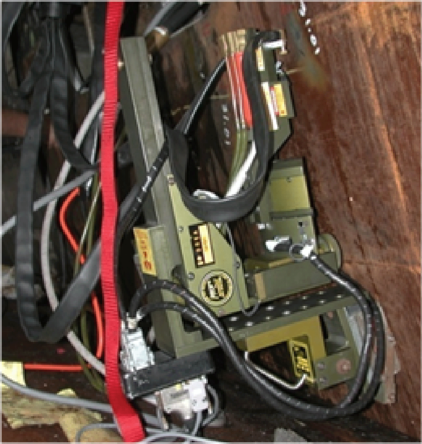
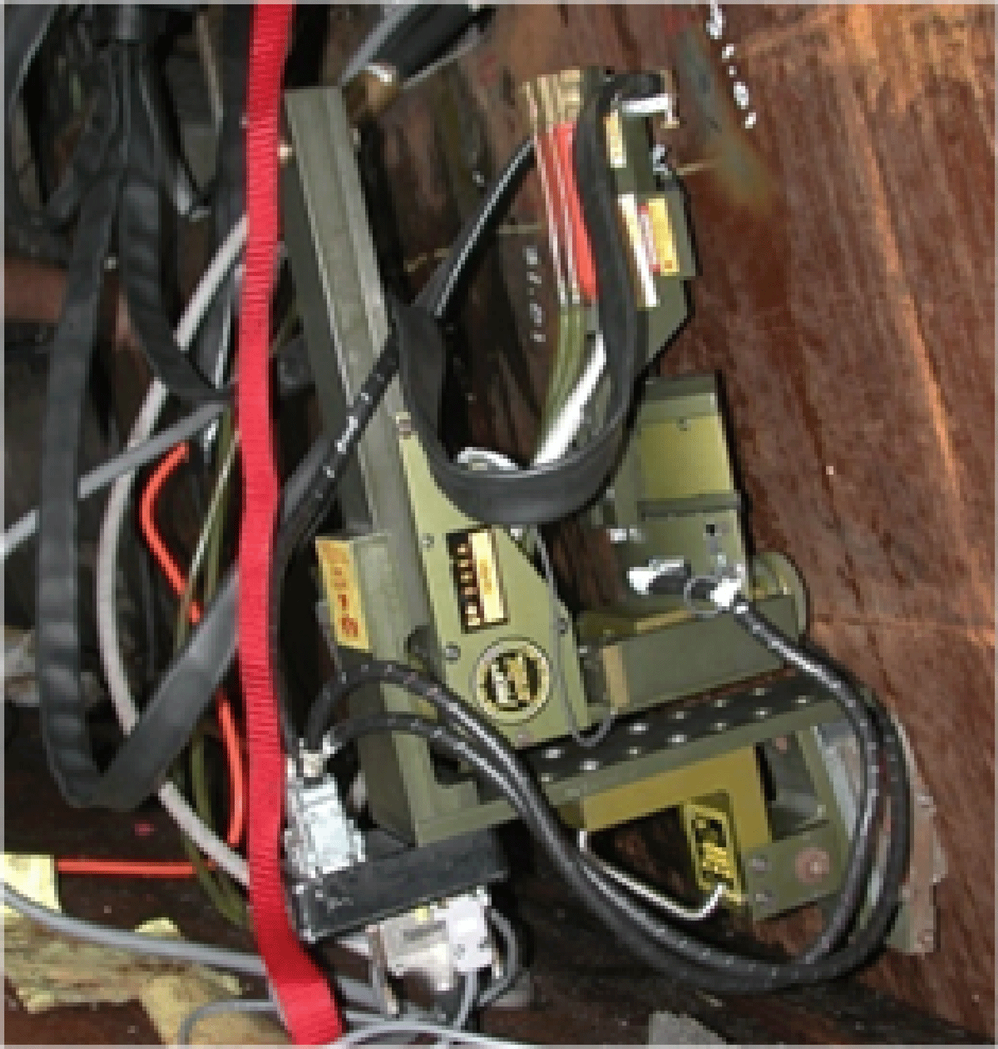
Figure 1. (Color online) The mXRD is shown during on-site measurement of residential stress on a submarine pressure hull. The mXRD goniometer is supported by the field stand that is attached to the submarine pressure hull using a large permanent magnet. The goniometer consists of the X-ray tube and beta rotation motors.
of 550 MPa (Farrell and MacGregor, Reference Farrell and MacGregor2008). The steel pressure hull is coated with a primer layer and an adhesive which is used to attach a layer of acoustic tiles. The shallow analysis depth of XRD methods (∼0.15 mm in steel) required that materials that inhibit X-ray penetration be removed prior to analysis. These layers represented physical barriers to the incident X-ray beam and were carefully removed to minimize cold work on the surface of the steel. Cold work often manifests as macrostrains and microstrains in the near surface (∼0.2 mm in steel) that induce stresses of up to ±25 MPa (Prevéy, Reference Prevéy and C.1991). Electropolishing to ∼0.2 mm depth has been shown to reduce the presence of stress imparted by mechanical surface preparation processes (Farrell and MacGregor, Reference Farrell and MacGregor2008).
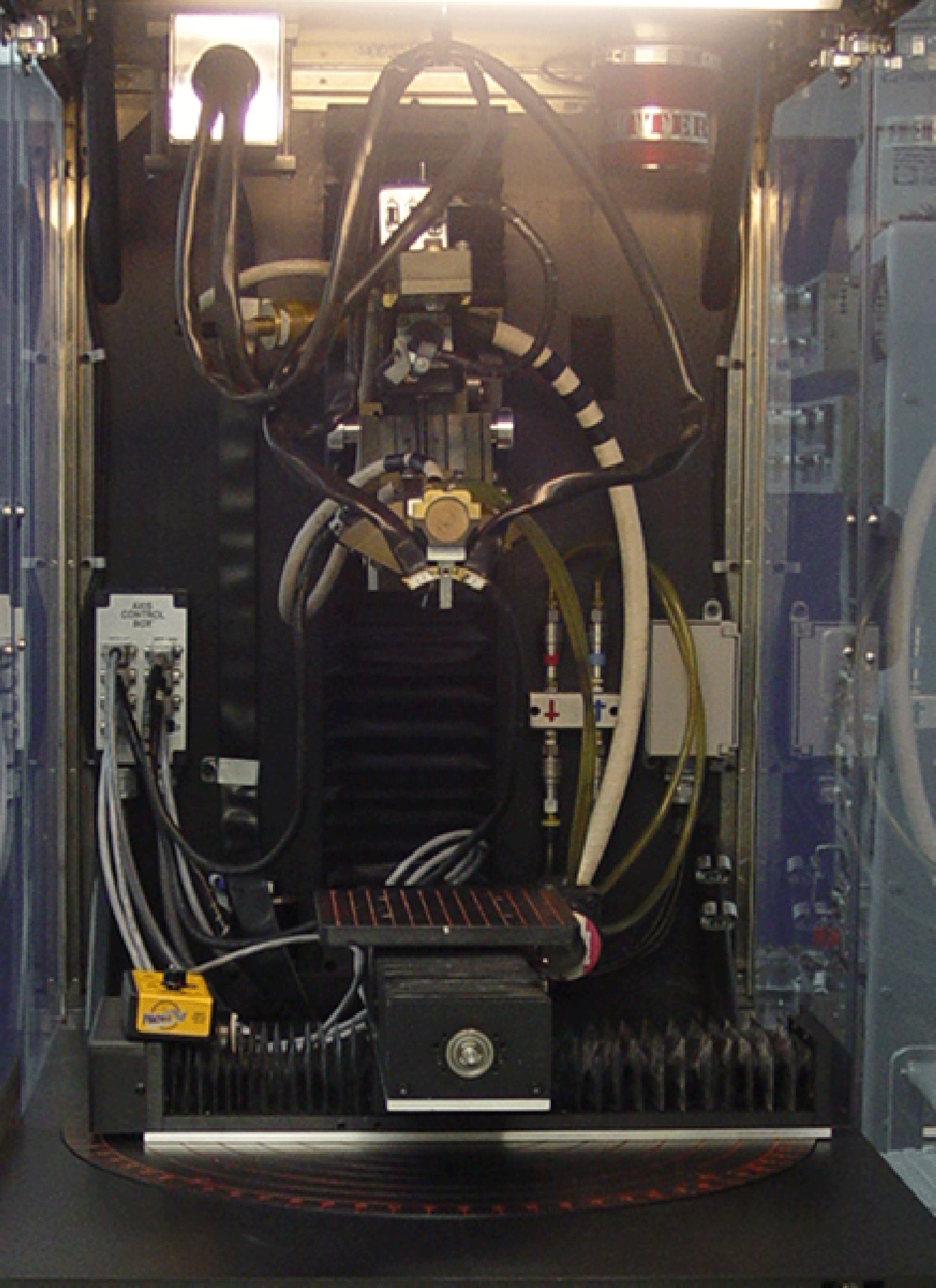
Residential strain measurements were made using a custom portable miniature X-ray diffractometer (mXRD) developed by Proto Manufacturing Co., Ltd (Brauss et al., Reference Brauss, Gorveatte and Porter1996). This system was developed specifically for portable in situ measurement of strain and quantification of stress in metallic structures. The principal components of the mXRD system consist of the computer and control unit, mXRD goniometer (with X-ray tube) and field stand, and position sensitive scintillation detector (PSSD). Figure 1 shows the mXRD on a submarine pressure hull during an on-site stress investigation. The mXRD goniometer is supported by the field stand that is attached to the submarine pressure hull using a large permanent magnet. The goniometer consists of the X-ray tube and beta rotation motors. Figure 2 shows the mXRD goniometer, field stand, and PSSD in the enclosure that is used for laboratory-based experiment. The four-point bend apparatus (center) and strain conditioner (lower left) that were used to derive the X-ray elastic constant (XREC) are also shown in Figure 2.
Strain measurements were made at 11 β angles using the multiple exposure technique. A Cr tube (Cr K α at 2.2910 Å) operating at 18.0 kV and 3.0 mA was used to diffract from the {211} plane of bcc Fe at a diffraction angle of about 156°. This, together with the X-ray penetration depth (∼0.15 mm), provided stress values from the outermost fibre
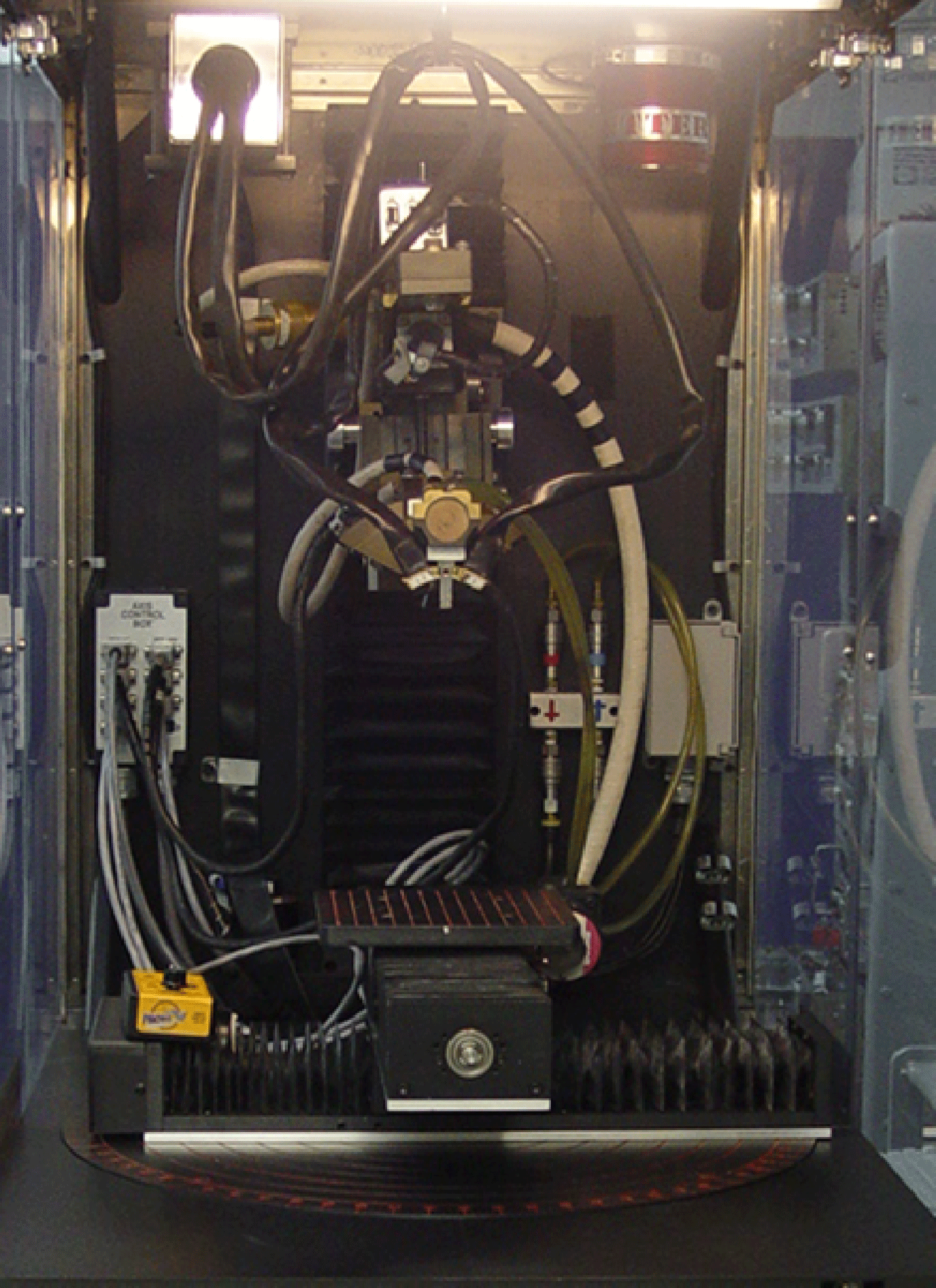
Figure 2. (Color online) The mXRD is shown within the safety enclosure that is used for laboratory-based measurements. The four-point bend apparatus, used to derive the XREC, is shown in the center of the photo, while the strain conditioner is on the lower left. The mXRD goniometer and field stand are immediately above the bend apparatus. The PSSD is positioned on the upper left (stainless steel box).
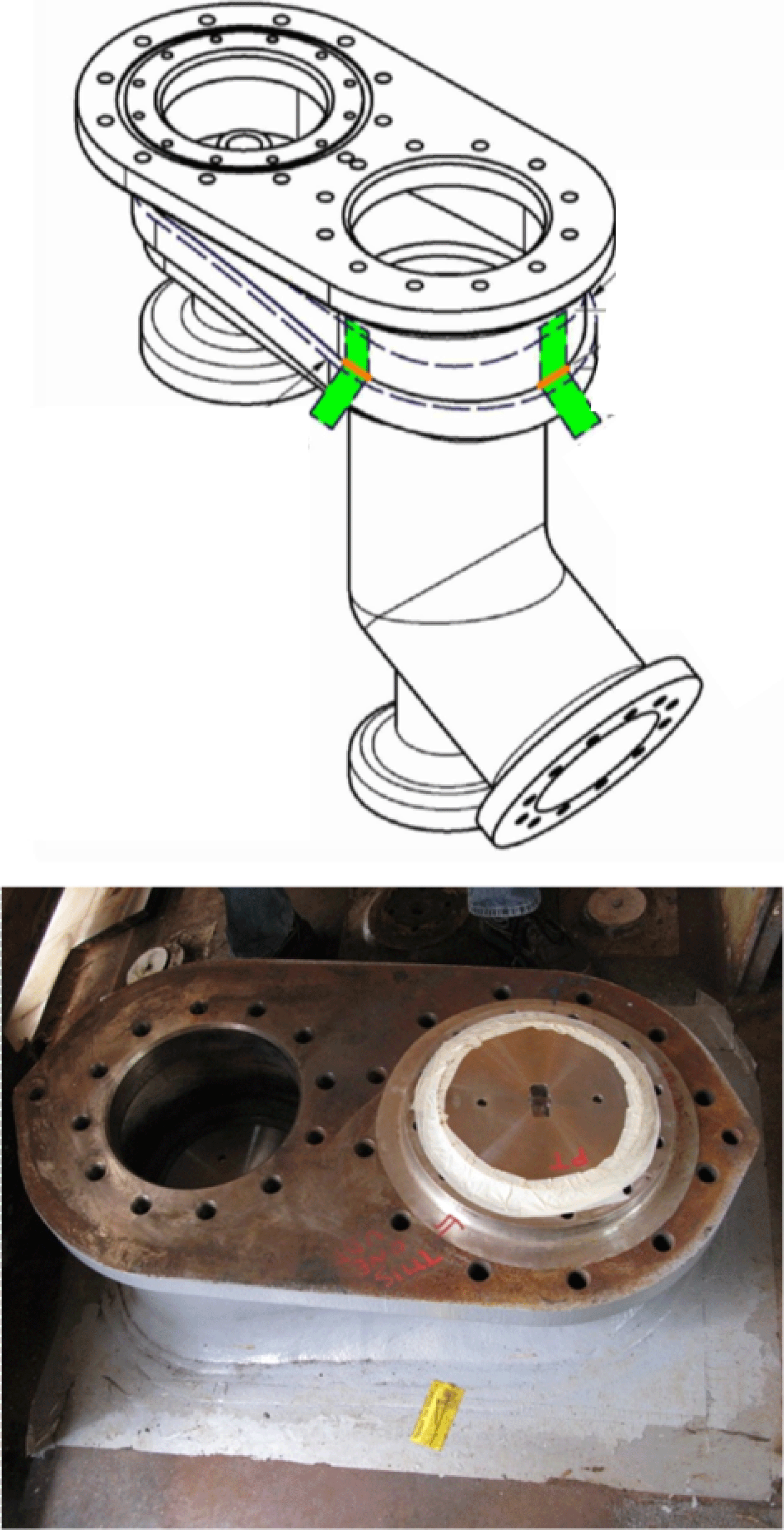
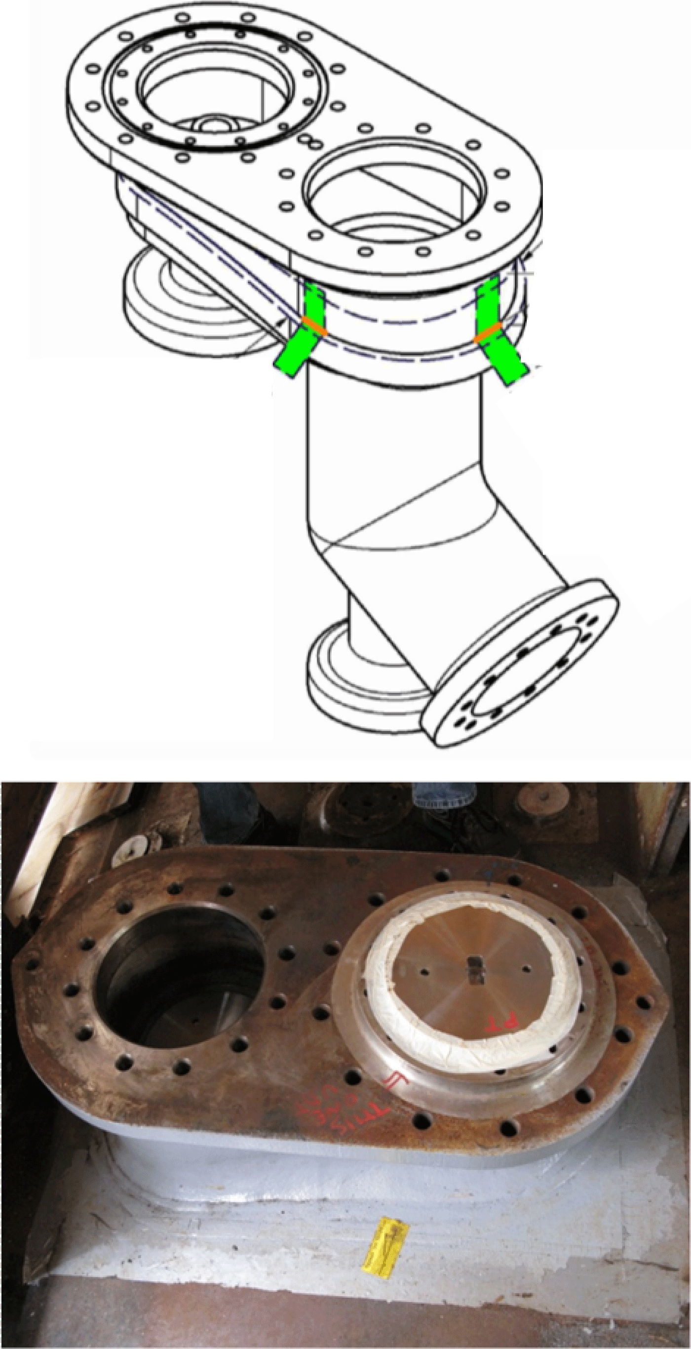
Figure 3. (Color online) Schematic (upper) and photograph (lower) of the DEHBUV on submarine A.
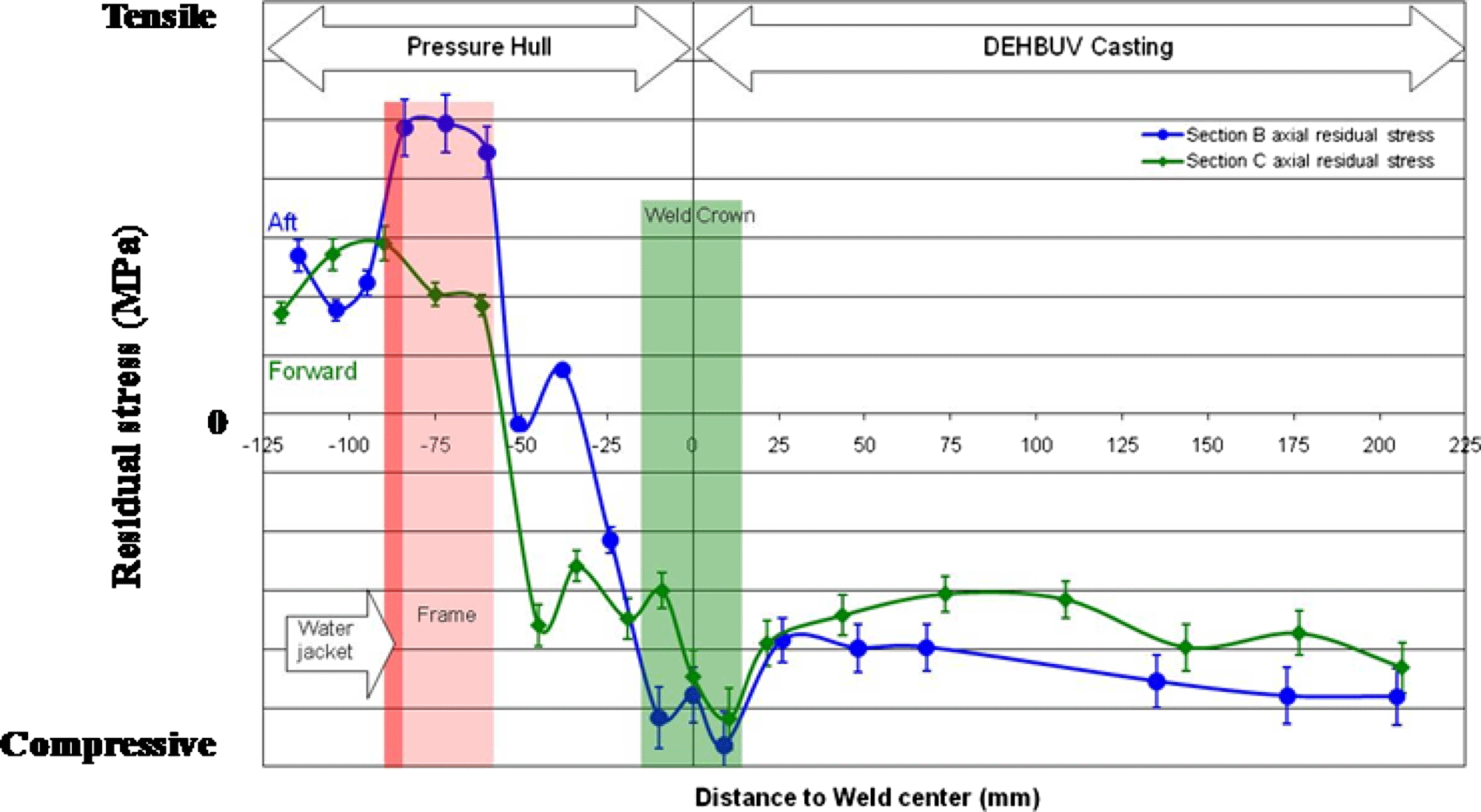
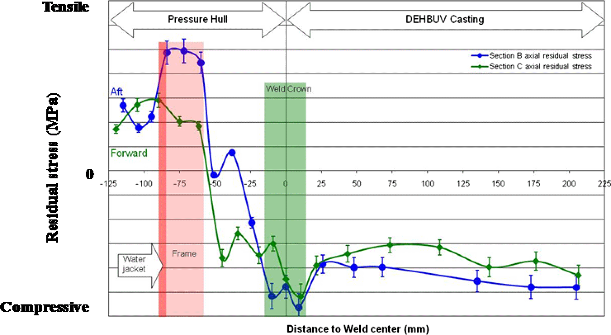
Figure 4. (Color online) Residential stress profiles across the DEHBUV and surrounding pressure hull of submarine A. Values were determined in the axial direction of the submarine perpendicular to the aft and forward DEHBUVs—pressure hull weld centerline.
of the submarine’s shell (within 0.35 mm). Measurements were performed using a 1.0 mm×3.0 mm rectangular aperture. Ten 2 s exposures for each XRD peak were taken requiring an elapsed time of 7–8 min. No filters were used on the detectors. A Gaussian function was used to fit the diffraction peaks.
The mXRD was calibrated using stress-free iron powder (99% pure) following ASTM specifications—an arithmetic mean of 14 MPa with a standard deviation of ±14 MPa (ASTM, 2000a). Periodic measurements on the iron powder were performed to verify that this calibration was maintained. For stress measurements, a conservative error estimate was used and stress values were believed to be accurate to the maximum of either ±28 MPa or 10% of the stress value. The spatial resolution for each measurement location was approximately ±5 mm.
Accurate depiction of residential stress state in submarine structures using X-ray diffraction requires reliable equipment and methodology for analysis. Stress values were quantified by multiplying strain values by a predetermined XREC following elastic theory (Farrell and MacGregor, Reference Farrell and MacGregor2008; ASTM, 2000b). While methods are available to calculate the XREC using elastic modulus and Poisson’s ratio or to estimate the XREC from literature sources for similar alloys, these methods often introduce significant errors. The spread between these values (both calculated and estimated) could be as high as 20% thus potentially resulting in stress errors of similar magnitude (Farrell and MacGregor, Reference Farrell and MacGregor2008). Four-point bend measurements were conducted in accordance to ASTM E-1426-98 to ascertain the stress-strain relationship (elastic modulus in bending) and the XREC for Q1N pressure hull steel. The ferrite phase (specifically the {211} planes of the Fe bcc structure) of the steel was used to calculate stress values. The XREC (for the {211} planes of the Fe bcc structure) for Q1N pressure hull steel was determined to be 195±6 GPa (Farrell and MacGregor, Reference Farrell and MacGregor2008).
III. RESULTS
A. Stress analysis of submarine A
During routine operations, submarine diesel exhaust hull and back-up valve (DEHBUV) materials (Figure 3) may suffer degradation of toughness. This is due to the localized high temperature environment associated with the exhaust gas flow experienced during operation of the submarine. DEHBUVs are periodically replaced to address this degradation. A residential stress investigation was conducted after replacement of the DEHBUVs on submarine A. This was done to

Figure 5. (Color online) Photograph showing the pressure hull of submarine B after removal of the affected plate. The location of the circumferential berthing weld is shown with a red box.
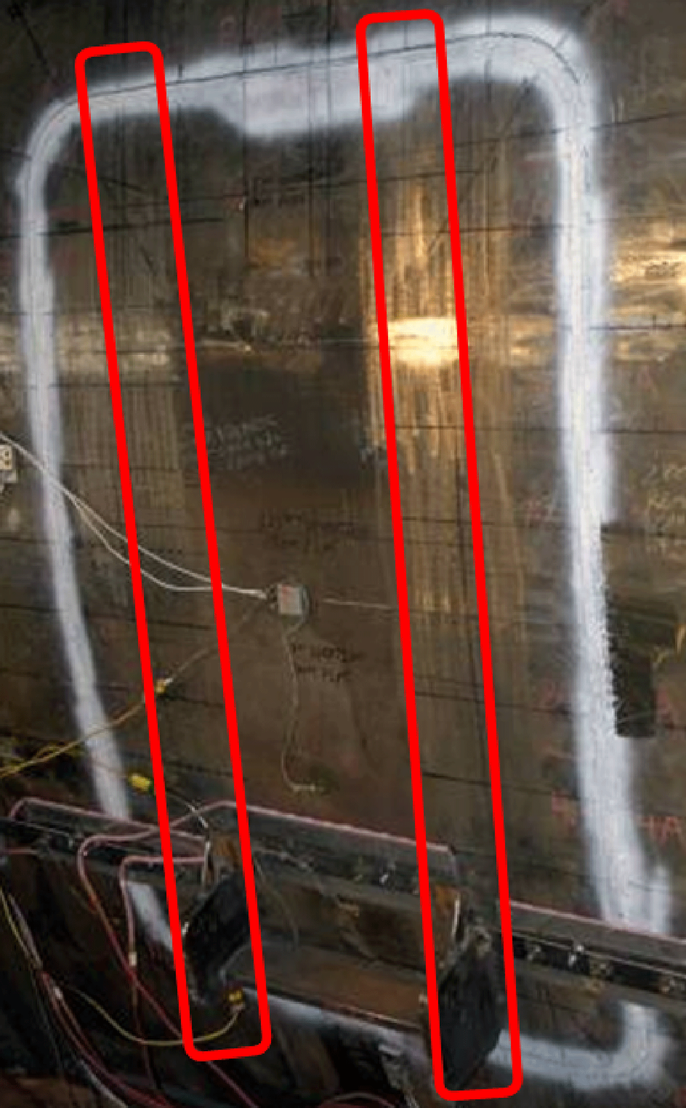
Figure 6. (Color online) Photograph showing the pressure hull of submarine B after insertion/welding of the new insert plate. The locations of the frames are shown with red boxes.
(1) assess the effectiveness of the DEHBUV insertion/welding and heat-treatment procedures and
(2) determine baseline residential stress values in order to assess the long term stress redistribution within the DEHBUV and surrounding submarine pressure hull.
Prior to this investigation, the replacement DEHBUVs were fabricated, heat treated, and then welded into the pressure hull. Stress analysis was conducted at a variety of locations on the exterior surface of the DEHBUVs and the surrounding pressure hull. The resultant stress profiles are shown in Figure 4. Stress values were determined in the axial direction of the submarine (perpendicular to the weld) on both the aft and forward sides of the DEHBUV. The lack of variation of stress values within the DEHBUV casting suggested uniform loading and the absence of casting and assembly stresses. The compressive stress values were not expected and were believed to reflect dry-dock loading strain. Further study is warranted to account for the shift to more compressive stress values.
The high tensile stresses that were determined on the exterior of the pressure hull over the frames (for Figure 4, this is shown aft of the DEHBUV) showed that the location of structural components has an impact on stress values. These surface values do not necessarily reflect values at depth. The electropolish depth (∼0.20 mm), together with the X-ray penetration depth (∼0.15 mm), provided analysis from the outermost fibre of the pressure hull steel surface (∼0.35 mm) only. These regions of high tensile residential stress represented areas of concern as they may be susceptible to crack initiation.
In terms of baseline residential stress levels, the complex local heating/cooling and resultant inhomogeneous volumetric changes associated with the weld crown and heat affected zone (HAZ) resulted in values that were quite variable. Although the present analysis showed little stress variation in the HAZ of welds, the limited spatial resolution of measurement techniques and the high stress gradient makes the HAZ region difficult for use as baseline values. It would be difficult to correlate present and future measurements as slight spatial differences could markedly affect the measured stress values. Therefore, only stress measurements taken outside of these areas will be considered as “baseline” values.
B. Stress analysis of submarine B
An extraction/insertion/weld repair procedure was conducted to repair a dent in the pressure hull of submarine B. During the weld repair, a portion of Q1N pressure hull plate that had been adversely affected by the dent was first removed (Figure 5). Then an HY80 plate, with similar

Figure 7. (Color online) Residential stress profiles transverse to the circumferential berthing weld and below the dent repair to the pressure hull of submarine B. Stress distribution is shown relative to the weld centerline.

Figure 8. (Color online) Residential stress profiles within 60 mm and transverse to the circumferential berthing weld below the dent repair to the pressure hull of submarine B. Stress distribution is shown relative to the weld centerline and shaded area shows the extent of the weld and HAZ.
mechanical properties and composition to Q1N steel, was fabricated, fitted up, and welded into the pressure hull cavity (Figure 6). This investigation was conducted to
(1) quantify the residential stress distribution/redistribution that occurred during the weld repair and
(2) determine baseline residential stress values to assess the long term stress redistribution within this region of the submarine pressure hull.
Prior to this investigation, a plate containing the dent had been extracted from the pressure hull of submarine B. Residential stress analysis was conducted at a variety of locations on the exterior surface of the pressure hull in the region affected by the dent repair. One area of interest was near the circumferential berthing weld that originally spanned the dented plate. Figure 7 shows stress profiles across the region of the circumferential berthing weld located below the dent repair (see red box in Figure 5). Prior to the dent repair, stresses were predominantly compressive with a low tensile stress at the toe of the berthing weld. Stress profiles before the weld repair were asymmetric and likely a consequence of mechanical constraint associated with the relative proximity of frames. Stresses in this region became more tensile after the weld repair. The profiles were also more symmetric after the weld repair. The redistribution of stress was more pronounced in locations near the circumferential berthing weld and over the frame welds.
A portion of the stress profiles that contains the weld and HAZ (shaded region) of the circumferential berthing weld is shown in Figure 8. Subsequent to the dent repair, axial

Figure 9. (Color online) Residential stress profiles (left) on frames welded to the pressure of submarine B (right). Dotted horizontal lines (left) depict the location of upper and lower plate welds.
stresses in the region were found to be similar to axial and hoop profiles before welding—predominantly compressive with a low tensile stress at the toe of the weld. Hoop stresses were significantly more tensile and had a maximum increase in tensile stress at the weld center.
Near the weld toe (Figure 8), the stress profile was expected to be symmetrical based on the classical examples in the literature (Masubuch, Reference Masubuch and D. W.1980). This was not the case. The asymmetry was likely primarily related to welding of the insert plate (to the pressure hull and frames). Weld shrinkage would be expected to cause increased tensile stress in the hoop direction in the pressure hull plate directly below the weld repair. The observed asymmetry in the circumferential butt weld was likely a consequence of nonuniform strains created during the insert plate welding process.
Inhomogeneous volumetric changes were likely the cause for the stress variation in profiles observed over frames 31 and 32 (Figure 9). Stresses at frame 31 and, to a lesser extent, frame 32 showed highly variable values. Stress values were determined in the near-surface region of the steel plate and may not reflect residential stress values within the bulk material. The regions of high tensile stress represented areas of concern as they may be susceptible to crack initiation. It has been envisioned that these highly variable and highly tensile residential stresses may reequilibrate during the “shakedown” period that is contemporaneous with the submarines’ initial deep dive. The validity of this statement is expected to be verified following activation of the submarine where the shakedown effect will be monitored with strain gages to provide real-time analysis and warning of impending issues.
IV. DISCUSSION AND CONCLUSIONS
It is no surprise that maintenance repairs to submarine pressure hulls have induced residential stresses that modified existing stress fields in the surrounding material. These repairs often give rise to high tensile stresses at weldments and localized variation in stress values. This is especially true near welded frames where highly variable and highly tensile stresses may develop. Regions of high tensile residential stresses may be susceptible to crack initiation in the future and require monitoring—these have implications to performance, safe operational limits, and service life of the submarines.
These investigations show the influence of plate and penetration (i.e., DEHBUV) weld repairs on the stress distribution in submarine pressure hulls. Stress analysis has also been used to gauge DEHBUV loading conditions and to provide baseline residential stress values to assess the long term stress redistribution in submarine pressure hulls. The elucidation of stress distribution is important to predicting the performance, safe operational envelope, and service life of naval structures.
ACKNOWLEDGMENTS
The authors thank Proto Manufacturing Co., Ltd for assistance with residential strain and stress analysis. The authors are much indebted to the staff of Defence R&D Canada–Atlantic and the Canadian Navies Fleet Maintenance Facilities in Esquimalt BC and Halifax NS for support to on-site analysis.


