NOMENCLATURE
- c m
specific heat capacity
 $| {\bar E}|$
magnitude of the electric field in the medium
- f
operating frequency
- q t
microwave power absorbed in the material
- T
temperature distribution function
- V
material volume
- $\alpha$t
thermal diffusivity
- $\varepsilon$0
electric permittivity of free space
- $\varepsilon$r
relative permittivity
- ${\varepsilon^{\prime}_r}$
real part of
$\varepsilon$r- ${\varepsilon^{\prime\prime}_r}$
imaginary part of
$\varepsilon$r- $\lambda$
wavelength in free space
- $\mu$
magnetic permeability
- $\rho$
mass density
- $\sigma$
electrical conductivity
- $\sigma$t
thermal conductivity
- $\omega$
angular frequency
- AI
artificial intelligence
- ATL
automated tape laying
- CFRP
carbon fibre-reinforced polymer
- CPW
coplanar waveguide
- CSRR
complementary split-ring resonator
- CT
computed tomography
- DIC
digital image correlation
- ECF
expanded copper foil
- EM
electromagnetic
- FMCW
frequency-modulated continuous-wave
- GFRP
glass fibre-reinforced polymer
- LSP
lightning strike protection
- NDT
non-destructive testing
- PCA
principal component analysis
- PCB
printed circuit board
- SEM
scanning electron microscopy
- SHM
structural health monitoring
- SRR
split-ring resonator
- SVM
support vector machine
- UAV
unmanned aerial vehicle
- UWB
ultra-wideband
- VNA
vector network analyser


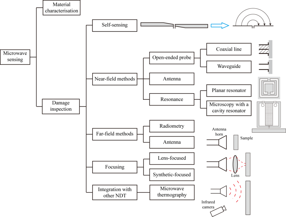
1.0 INTRODUCTION
Compared with traditional materials used in aircraft structures, carbon fibre-reinforced polymer (CFRP) and glass fibre-reinforced polymer (GFRP) composites can provide a higher strength-to-weight ratio, and good fatigue and corrosion resistance(Reference Soutis1). CFRP composites are often used in primary structures, such as wings, fuselage and rear pressure bulkhead, whereas GFRP composites are mainly used in secondary structures, such as radomes. Visual inspection and liquid-coupled ultrasonics are commonly applied in service to examine the structural integrity. Visual inspection is performed with naked eyes for observation of any surface damage, and the accuracy is dependent on the inspector’s experience, lighting conditions and access to structures. Liquid-coupled ultrasonics can be used for inspection of internal defects/damage, and couplants (water or gels) are usually needed. There is ongoing research on other non-destructive testing (NDT) techniques for more accurate evaluation and convenient implementation, such as acoustic emission(Reference Chandarana, Sanchez, Soutis and Gresil2-Reference Bache8), guided waves(Reference Kessler, Spearing and Soutis9-Reference Khan, Shin, Lim, Kim and Kim18) (e.g. piezoelectric transducer-based(Reference Qing, Li, Wang and Sun19,Reference Mei, Haider, Joseph, Migot and Giurgiutiu20) and angle beam transducer-based(Reference Mei, Haider, James and Giurgiutiu21,Reference Wang, Liu, Cao, Yang, Su and Cui22) ), air-coupled ultrasonics(Reference Derusova, Vavilov, Druzhinin, Kolomeets, Chulkov, Rubtsov and Kolubaev23-Reference Kazys and Vilpisauskas30), thermography(Reference Boccardi, Carlomagno, Boffa, Ricci and Meola31-Reference Chandarana, Lansiaux and Gresil36), optical fibre sensing(Reference SÁnchez, Gresil and Soutis37-Reference Serovaev and Kosheleva42), digital image correlation (DIC)(Reference Saleh, Yudhanto, Potluri, Lubineau and Soutis43-Reference Oz, Mehdikhani, Ersoy and Lomov48), electromagnetic testing(Reference Li, Haigh, Saleh, Mccarthy, Soutis, Gibson and Sloan49-Reference Salski, Gwarek and Korpas51) (e.g. eddy current(Reference Heuer, Schulze, Pooch, GÄbler, Nocke, Bardl, Cherif, Klein, Kupke, Vetter, Lenz, Kliem, BÜlow, Goyvaerts, Mayer and Petrenz52-Reference GÄbler, Heuer and Heinrich58)) and X-ray imaging(Reference Wang, Burnett, Chai, Soutis, Hogg and Withers59,Reference Emerson, Wang, Withers, Conradsen, Dahl and Dahl60) . In particular, acoustic emission sensors are used to detect bursts of acoustic waves from the fracture events (e.g. fibre-matrix disbonding and cracking) during the measurement. The guided wave and optical fibre sensing techniques are widely used for structural health monitoring (SHM), where sensors are placed on/in the structure. For thermography, very large structures can be monitored in a short time period, while only surface and subsurface damage can be identified due to poor penetration. The DIC method is primarily employed for strain measurement, where the locations of small dots painted on the surface are closely monitored with optical cameras. X-ray imaging can help examine the real damage distribution in high definition, while the sample size is limited and special protection against ionising is required. Hence, it is seen that each method has its advantages and disadvantages.
An alternative and emerging method is the microwave technique. Microwave frequencies range from 300MHz (wavelength of ~1m) to 300GHz (wavelength of ~1mm). Microwaves can propagate in air and dielectric materials with low attenuation. When microwaves interact with matter, the rotation of dipolar molecules or movement of ions/electrons will be produced(Reference Metaxas and Meredith61). Any variation of the electromagnetic (EM) properties can be revealed in the signals received. For composites, microwave testing methods have been developed for monitoring automated tape laying (ATL) processes(Reference Wilson, Moore and Juarez62), detection of impact damage(Reference Greenawald63-Reference Li, Wang, Haigh, Meng and Wang65), delamination(Reference Hosoi and Ju66-Reference Case, Kharkovsky, Zoughi, Steffes and Hepburn68), air voids(Reference Umeda, Miyashita and Kako69), lightning strike damage(Reference Todoroki, Ohara, Mizutani, Suzuki and Matsuzaki70,Reference Rufail, Laurin and Moupfouma71) and moisture ingress in sandwich structures(Reference Ravuri, Abou-Khousa, Kharkovsky, Zoughi, Austin, Thompson and Chimenti72,Reference Wang, Pei and Zhou73) . Compared with the other NDT methods, microwave testing has the advantages of being non-contact, no need for surface transducers, couplants or complicated signal post-processing, it is operator friendly, relatively inexpensive and has no ionising hazards(Reference Ibrahim74-Reference Pakkathillam, Sivaprakasam, Krishnamurthy and Arunachalam77).
Microwave testing has a long history dating from the early 1950s, and interests in this technique have grown in recent years. In 2011 the expert committee for microwave and terahertz testing procedures of the German Society of Non-Destructive Testing (DGZfP) was founded, and in 2014 the microwave testing committee was established by the American Society for Non-destructive Testing (ASNT). In 2015 the British Institute of Non-Destructive Testing (BINDT) introduced a user group focused on terahertz, microwave and millimetre methods. Microwave testing was recognised as its own NDT method in the 2016 edition of the ASNT standards. In 2017, the Boeing Company set up a new microwave laboratory for non-destructive detection of potential flaws in coatings, surfaces and structures(Reference Careaga78).
For NDT purposes, the signal power used is generally very low (up to a few milliwatts), so little heating effect is observed. On the other hand, at high power levels microwaves can be used as a heat source. There are several benefits that microwave heating can bring about, such as elimination of a hot heat source, no need for insufficient heat transfer equipment, improved volumetric heating, better heating efficiency and precise on-off control of heating. In addition, microwave heating has a distinctive feature of selective heating, which means in a mixture the constituents with higher loss factors will be more heated and the other constituents are heated by conduction and/or convection. In glass fibre composites the resin is more readily heated, and this type of heating is often grouped as dielectric heating. However, with carbon fibre composites the fibres present the higher loss factor and are heated by induced currents known as induction heating. Owing to the superior energy transfer, microwaves have been applied for curing(Reference Methven, Ghaffariyan and Abidin79-Reference Boey, Gosling and Lye84), three-dimensional (3D) printing(Reference Li, Link and Jelonnek85), joining(Reference Bajpai, Singh and Madaan86-Reference Sosa, Worthy and Darlington89), de-icing(Reference Feher90,Reference Madi, Pope, Huang and Iqbal91) , thermography(Reference Swiderski, Szabra and Wojcik92-Reference Chady97) and recycling(Reference Torres, De Marco, Caballero, Laresgoiti, ChomÓn and Kondra98,Reference Åkesson, Foltynowicz, ChristÉen and Skrifvars99) .
The existing review papers are more limited to a specific field, such as curing(Reference Thostenson and Chou100-Reference Mgbemena, Li, Lin, Liddel, Katnam, Thakur and Nezhad102), joining(Reference Choudhury and Debnath103) or damage inspection(Reference Kharkovsky and Zoughi104-Reference Zhang, Yang, He, Foudazi, Cheng and Tian106). The materials discussed are of different types, generally not focused on aircraft composites. Hence, an overview of the microwave non-destructive testing and heating capabilities for CFRP and GFRP composites is needed. In this paper, a comprehensive review is provided, addressing the recent research progress, challenges and trends. First, the electromagnetic properties of composites and general classification of microwave sensing approaches are discussed. Then, the sensing and heating applications in the life cycle of composite structures are presented, from manufacturing (e.g. curing, joining and quality check), strain sensing and damage detection to recycling processes. Besides, the remaining challenges and trends are outlined.
2.0 INTERACTION BETWEEN MICROWAVES AND COMPOSITES
2.1 Electromagnetic properties of composites
As illustrated in Fig. 1, when microwave energy is directed towards a composite sample, the energy is reflected, transmitted and absorbed. In each of the three cases the specific portion of energy is directly associated with the electromagnetic properties. Here the permittivity (or dielectric properties)  $\varepsilon$ is the parameter of interest, whereas the magnetic permeability is not considered as both fibres and epoxy are non-magnetic.

Figure 1. Interaction between microwave energy and a material.
The permittivity  $\varepsilon$ can be expressed as
 \begin{align}\varepsilon = {\varepsilon _0}{\varepsilon _r} = {\varepsilon _0}\!\left( {{\varepsilon^{\prime}_r} - j{\varepsilon^{\prime\prime}_r}} \right) = {\varepsilon _0}{\varepsilon^{\prime}_r}\left( {1 - j\tan \delta } \right)\end{align}
where  $\varepsilon$0 is the permittivity of free space (i.e. 8.8542 × 10⁻¹²F/m), and
  $\varepsilon$r is the relative permittivity.
  ${\varepsilon^{\prime}_r}$ is related to the ability to store the electric field energy, while
  ${\varepsilon^{\prime\prime}_r}$ accounts for the dissipation of the energy within the material in the form of heat. The loss tangent (tan
  ${\delta=\varepsilon^{\prime\prime}_r}$/
 ${\varepsilon^{\prime}_r}$) can also be used for the description of the dielectric loss.
Any material can be characterised by its complex permittivity, and it can be measured using many methods, such as the transmission line, open-ended waveguide/coaxial line, resonant and free-space methods(Reference Chen, Ong, Neo, Varadan and Varadan107-Reference Li, Haigh, Soutis, Gibson and Sloan111). Compared with GFRP composites, CFRP composites are lossier and the signal penetration is lower(Reference Li, Haigh, Soutis and Gibson112,Reference Chin and Lee113) . More energy can propagate in the CFRP composites when the signal polarisation is perpendicular to the fibre direction.
2.2 Microwaves for heating
With higher microwave signal power, more energy will be absorbed within the material. The temperature rise caused can be analysed using the heat equation:
 \begin{align}{{\partial T} \over {\partial t}} = {\alpha _t}\!\left( {{{{\partial ^2}T} \over {\partial {x^2}}} + {{{\partial ^2}T} \over {\partial {y^2}}} + {{{\partial ^2}T} \over {\partial {z^2}}}} \right) + {1 \over {{c_m}\rho }}{q_t}\end{align}
where T(x, y, z, t) is a temperature distribution function of three spatial variables (x, y, z) and the time variable t.  $\alpha_{\rm t}=\sigma_{\rm t}/c_{m}\rho$ is the thermal diffusivity, and
  $\sigma$t is the thermal conductivity. c m is the specific heat capacity, and
  ${\rho}$ is the density. q t is the microwave power absorbed in the material and can be given by (for non-magnetic materials)(Reference Ayappa, Davis, Crapiste, Davis and Gordon114)
 \begin{align}{q_t} = {{\omega {\varepsilon _0}{\varepsilon^{\prime\prime}_r}} \over 2}\int_V {{{\left| {\bar E} \right|}^2}dv} \end{align}
where  $\omega=2\pi f$ is the angular frequency in rad/s, and f is the operating frequency.
  $\left| {\bar E} \right|$ is the magnitude of the electric field in the medium. V is the material volume. It is noted that microwave heating is more suited to CFRP composites for the higher electrical conductivity.
For accurate analysis of the heating effect, multi-physics modelling (i.e. electromagnetic and thermal coupled simulation) should be introduced(Reference Lorence and Pesheck115). Modelling microwave heating at high power is extremely challenging. During the heating process, the geometry may change and the constitutive parameters are temperature dependent. The EM field distribution in the computational domain continuously changes as the temperature rises or falls; the changes in the EM field distribution can also cause temperature changes. Therefore, it’s a highly iterative nonlinear modelling problem that has so far not been thoroughly solved and hence the manufacturing process is still suboptimal.
2.3 Microwaves for damage evaluation of composites
The most straightforward microwave sensing is to make the sample under test part of a microwave component (e.g. a transmission line, a waveguide or an antenna). Any defect/damage can be detected by comparing the signals with a reference, achieving self-sensing/online monitoring. The other types of microwave testing can be categorised into near- and far-field approaches, according to the distance between the probe and the sample. The term ‘near field’ refers to the evanescent field of an open-ended transmission line/waveguide or the region near an antenna(Reference Balanis116). When an object is placed in this region, the distributions of the electric currents on the probe are affected and the changes are indicated in the reflection coefficient (S11). The far field is the region of operation for most antennas, where the radiation pattern does not change with distance. A general classification of the microwave sensing methods for composites is presented in Fig. 2. Detailed descriptions of the detection principles, setups and probes used in each method can be found in Refs. Reference Case and Kenderian117–Reference Ida119. The focusing methods and microwave thermography can be adopted in either the near or far field.

Figure 2. General classification of the existing microwave sensing approaches for composites.
3.0 APPLICATIONS OF MICROWAVE HEATING FOR COMPOSITES
3.1 Curing
Composite components are manufactured by curing the mixture of fibres and resin into the desired properties and shapes. Conventionally, the curing is conducted in an autoclave. However, the heat transfer inside the autoclave is slow, as it relies on air convection and then conduction through the composites as well as tooling and consumables. Thus, very high thermal gradients should be maintained, posing some non-uniform cooling problems. It usually takes many hours to cool down the autoclave. Therefore, there is a need for more efficient manufacturing technologies(Reference Hassan and Ganjeh120).
Microwave curing is of great interest to the aircraft industry, due to the potential of reduction in curing time and energy. The volumetric capability facilitates heat transfer through the laminate thickness(Reference Green, Nuhiji, Zivtins, Bower, Grainger, Day and Scaife82,Reference Thostenson and Chou121) , resulting in a faster and more uniform temperature distribution. The mechanical properties of the composite can be increased due to the stronger bonding at the fibre-matrix interface(Reference Drzal, Hook and Agrawal122). In addition, only the composite is heated rather than the whole oven space, leading to significant energy saving.
Lee et al.(Reference Lee and Springer123) proposed an analytical model to simulate the microwave curing process. Experiments were made with composites placed in a commercially available microwave oven. The temperatures inside the oven were measured by thermocouples. The temperature distribution was compared with the results calculated with the model for the conditions employed in the tests, and good agreement was found. Parametric studies were also performed to determine the appropriate cure cycle for uniform curing and minimum heating time.
Agrawal et al.(Reference Agrawal and Drzal124) studied the effect of microwave curing on fibre-matrix adhesion. Composite specimens were made in a TE111 mode cylindrical cavity. In each specimen a single fibre was embedded in an epoxy matrix. From the tensile tests, it was revealed that for glass fibre-epoxy and aramid fibre-epoxy specimens the fibre-matrix interfacial shear strength was decreased by 15% compared with the conventional thermal curing. For either system, the fibre failure mode was interfacial failure as in the thermally cured specimens. For carbon fibre-epoxy specimens, the interfacial shear strength of the microwave-cured specimens was increased by 70% compared with that of the thermally cured ones. And the fibre failure mode was changed to matrix failure. Under 4.5watts of microwave power, the interphase temperature was found 75°C higher than the bulk temperature, resulting in a faster curing reaction.
Boey et al.(Reference Boey, Gosling and Lye84,Reference Boey and Lee125) used microwaves to cure woven E-glass fibre composites. The sample was placed in a cavity powered by a 2.45GHz magnetron. Compared with the conventional thermal curing, faster curing was achieved in minutes rather than hours. The mechanical strengths provided were not lower than those produced by the thermal curing, and the modulus value was significantly increased. A 100mm thick specimen was found uniformly heated throughout the thickness. Lind et al.(Reference Lind, Wear and Kurz126) designed an open-ended single-mode cavity and consolidated a thermoplastic carbon fibre prepreg in-situ as the composite was formed in the fibre placement process, where microwave signals selectively heated the top layer of the composite.
Li et al.(Reference Li, Li, Zhou and Cheng80) developed a new technique to cure multidirectional CFRP composites using metal strips, which were applied on the top and bottom surfaces of CFRP with insulation film in between. Under microwave irradiation, a coplanar waveguide (CPW) structure was generated, and the electric field coupled was perpendicular to the composite surface. In the experiment microwave power of 3kW at 2.45GHz was applied. An infrared camera was used to measure the temperature distribution of the composite parts. From the thermal images and curing temperature measured by optical fibre sensors, it was shown that a 2.3mm thick composite sample can be effectively cured.
Zhou et al.(Reference Zhou, Li, Li and Wen127) proposed a learning-based intelligent temperature control method to achieve homogeneous microwave curing of CFRP composites. A unidirectional composite plate (500mm × 400mm × 2mm) was processed for validation. The self-developed high-pressure microwave curing equipment (frequency of 2.45GHz, power of 31.5kW and pressure of 2.0MPa) shown in Fig. 3 was used. There were 21 microwave sources symmetrically distributed on each side of the heptagonal cavity. Twenty optical fibre probes were employed to monitor the temperature distribution on the composite surface. Conventional neural networks were used to learn the dynamic temperature behaviours of the composites during curing under various control schemes. Based on the temperature monitoring results, active temperature compensation was implemented to control the microwave power. It was indicated that the average temperature difference on the composite surface was reduced by 42.3% compared with the random compensation method and 31.6% compared with the semi-direct neural network control method.

Figure 3. Photograph of the microwave curing equipment and optical fibre sensors used for temperature control(Reference Zhou, Li, Li and Wen127).
Li et al.(Reference Li, Link and Jelonnek85) proposed a novel 3D printing method, where microwaves were used to heat the continuous CFRP filaments. A temperature control method was presented to reduce the temperature difference of the filaments at different printing speeds. Utilising the advantages of microwave heating, a high printing speed of 20mm/s was achieved, and the average tensile strength of the specimens was about 358MPa. In comparison, the printing speed by the convectional heating method was only 5mm/s, and the average tensile strength was about 303MPa.
The Hephaistos applicator(Reference Feher90) is one of the microwave curing systems available in the market. In Hephaistos, there are 12 non-resonant slotted waveguides around the edges of the hexagonal cavity. Due to the high transmission efficiency of the waveguide systems, no waveguide circulators or additional cooling devices are needed. Magnetrons are directly mounted on the waveguides and each consumes a power level of 700–800W.
3.2 Joining
Compared with adhesive bonding and mechanical fastening, microwave joining is more energy efficient and needs less operation time. Composite parts can be joined directly by microwave heating. Alternatively, conductive/magnetic particles (microwave susceptible implants) can be placed in the bond line of the joint for composites with a low  ${\varepsilon^{\prime\prime}_r}$.
There are two types of resins: thermoset and thermoplastic. Thermoset resins (e.g. epoxy resin) are more widely used and liquid at room temperature, thus convenient for impregnation of fibres and hardening at a higher temperature (curing temperature). The thermoset cannot be remoulded after the initial forming. In comparison, thermoplastic resins are solid at room temperature and melt when heated. The shape of the thermoplastic composites can be moulded and remoulded(Reference Varadan and Varadan88,Reference Sosa, Worthy and Darlington89) , so thermoplastic composites are more suitable for joining and in-situ repair operations.
Ku et al.(Reference Ku, Siores and Ball128) examined the joining of 33% by weight of random glass fibre-reinforced Nylon 66, polystyrene (PS) and low-density polyethylene (LDPE) as well as 23.3% by weight of carbon fibre-reinforced PS thermoplastic composites. A WG9A waveguide with slits opened for positioning of the test pieces was placed upright within a modified commercial microwave oven. The upper end of the waveguide was fitted with a flange connected to a magnetron, and the lower end was attached to an additional length of waveguide containing a shorting plunger. For each material type, the test pieces were welded using constant power of 240W and an exposure time of 5s. From the tensile tests, it was shown that the bond strengths of all the materials ranged from 8.5% to 24.3% of those of the respective parent materials.
Bajpai et al.(Reference Bajpai, Singh and Madaan86) studied microwave joining of natural fibre-reinforced polymer composites. In this work, natural fibres (nettle and grewia optiva plant fibres)-reinforced polylactic acid (PLA) green composites and polypropylene (PP)-based partially biodegradable composites were developed. Lap joints of these composites were prepared in a microwave oven. The specimens were exposed at a power level of 900W: 200s for the PLA-based composites and 250s for the PP-based composites. Charcoal powder was used as a susceptor and placed close to the joint area to accelerate the heating. Araldite standard epoxy adhesive was used for comparison, and the curing was done at room temperature for 24h. It was seen that a higher joint strength was provided by the microwave approach.
Several factors can affect the overall joining performance, such as frequency, power and processing time. Single-frequency processing can readily cause hot spots, while variable frequency processing can be used for more uniform heating. The input power should not be set too high to avoid potential overheating. It was indicated that the strength of the joint was increased as the exposure time increased up to a certain level beyond which the strength was decreased(Reference Ku, Macrobert, Siores and Ball129).
3.3 Recycling
During the manufacturing of carbon fibre composites, about 30% of the prepreg material is wasted as offcuts, which have to be landfilled(Reference Lester, Kingman, Wong, Rudd, Pickering and Hilal130). To meet more stringent environmental legislation, many recycling techniques have been developed, such as mechanical processes (mainly grinding), thermal processes (e.g. pyrolysis, fluidised bed pyrolysis and microwave-assisted pyrolysis) and solvolysis(Reference Oliveux, Dandy and Leeke131). In microwave pyrolysis, an organic material is heated in an inert environment and the material is decomposed into low molecular weight substances. For composites, the resin degrades into a mixture of hydrocarbons, while the fibres are left intact. Thus, the fibres can be separated from the matrix and reused(Reference Torres, De Marco, Caballero, Laresgoiti, ChomÓn and Kondra98). The advantages of microwave pyrolysis include fast thermal transfer, increased process yield and environmental compatibility(Reference Jones, Lelyveld, Mavrofidis, Kingman and Miles132).
Lester et al.(Reference Lester, Kingman, Wong, Rudd, Pickering and Hilal130) investigated the applicability of recovering carbon fibres using the experimental setup illustrated in Fig. 4 (a). Four 3g composite sheets were suspended in a bed of quartz sand, which is transparent to microwaves. A steady stream of nitrogen gas (5L/min) was used to create an inert atmosphere and prevent combustion of the fibres during 8s heating in the multimode microwave cavity (3kW). Glass wool was used to prevent the solids leaving the cavity through the glassware. A gas trap was used to reduce the amount of polymer in the exhaust gases reaching the vent. The fibres recovered were characterised by scanning electron microscopy (SEM) and tensile tests. As shown in Fig. 4(b), the fibres were relatively clean, although there were some small changes in the surface topology. The fibre strength retention (80%) was better than that of the fibres recovered by fluidised bed processing (74%).

Figure 4. Recovery of fibres from CFRP composites using microwaves(Reference Lester, Kingman, Wong, Rudd, Pickering and Hilal130): (a) schematic diagram of the setup (b) a view of multiple recovered fibres using scanning electron microscopy.
Akesson et al.(Reference Åkesson, Foltynowicz, ChristÉen and Skrifvars99) employed microwave pyrolysis to recycle glass fibre composites. A scrap wind turbine blade was fragmented and pyrolysed at 300–600°C for about 90min in a nitrogen atmosphere. Microwaves were generated with three magnetrons, and the maximum power of each magnetron was 1kW. The tensile tests showed that the fibre strength was reduced by about 25% after pyrolysis. The recovered fibres were then used to produce new thermoset composites. It was found that with 25wt% of the recycled fibres relatively good mechanical properties were obtained.
Currently, little commercialisation is seen in the recycling. One of the difficulties is the scale-up of the laboratory units to industrial capacities. Detailed knowledge of microwave engineering is required to better design the heating equipment and fully interpret the signal responses. To achieve uniform heating, important operating parameters that should be considered include radiation time and power, cavity design and material throughput(Reference Mgbemena, Li, Lin, Liddel, Katnam, Thakur and Nezhad102,Reference Appleton, Colder, Kingman, Lowndes and Read133) . Without efficient control and optimal cavity design, non-uniform heating can occur, resulting in hot spots and reduced energy efficiency. Conventional heating can be used together for improved uniformity through the thickness(Reference Janney, Calhoun and Kimrey134). Alternatively, radio frequency heating can be considered, as it is widely used for large scale industrial processes.
3.4 Damage inspection
High-power microwaves can be integrated with conventional thermography for non-contact detection. Owing to the good performance of commercial infrared (IR) cameras, high sensitivity and spatial resolution can be offered. In addition, rapid inspection can be carried out over a large area. In a typical setup, a horn antenna is used to direct the waves into the region of interest. Different signal excitation settings can be adopted, such as lock-in, pulsed, step and pulsed phase modes(Reference Swiderski, Szabra and Wojcik92). An IR camera can be located on the same side of the excitation source (reflection configuration) or the other side (transmission configuration). Special attention should be paid to electromagnetic shielding when high power is used. Like microwave thermography, other detection methods can be combined to compensate the strengths and weaknesses of each method.
Galietti et al.(Reference Galietti, Palumbo, Calia and Pellegrini93,Reference Palumbo, Ancona and Galietti96) used microwave lock-in thermography to assess the impact damage in CFRP composite specimens. The samples were heated in a microwave oven, and an IR camera was positioned 150mm from the window of the cooking chamber. The damage areas revealed showed good agreement with those given by the X-ray images. Four sandwich specimens were also examined by microwave pulsed thermography. Given the differences in the non-linear heating and cooling curves of the damaged and undamaged areas, a new data processing algorithm was proposed for quantitative analysis. The results provided were also consistent with those by the X-ray imaging and conventional lock-in thermography.
Chady et al.(Reference Chady97) developed a microwave pulsed thermography system for the detection of delamination in a GFRP composite sample. The system is presented in Fig. 5(a), and it consisted of a 2.45GHz magnetron, an IR camera, an open-ended rectangular waveguide and a cooling device. The maximum power of the magnetron was 1kW. The sample was located directly under the waveguide and heated for 30s. As shown in Fig. 5(b), delamination was revealed in the thermogram.

Figure 5. A microwave thermography system for the detection of delamination in a GFRP composite sample(Reference Chady97): (a) test setup (b) raw thermogram with the delamination region marked.
4.0 APPLICATIONS OF MICROWAVE SENSING FOR COMPOSITES
Use of lower-power microwaves for monitoring and damage assessment can be found in a number of review papers(Reference Kharkovsky and Zoughi104,Reference Zhang, Yang, He, Foudazi, Cheng and Tian106,Reference Case and Kenderian117,Reference Li, Haigh, Soutis, Gibson and Wang135) . For completeness and to avoid unnecessary repetition, only typical and new examples closely associated with composites are presented here.
4.1 Monitoring of fibre tow angle
ATL is an effective method of placing wide carbon fibre prepreg tapes (76.2, 152.4 or 304.8mm wide) on relatively large flat or minimally curved surfaces(Reference Grant136). There are typically full-stop inspection operations to determine if the tape angle deviations are acceptable. Currently, visual inspection is usually performed, but the process is time consuming and the costs are high. Hence, an automated approach for on-site monitoring of the tape angle is needed.
Wilson et al.(Reference Wilson, Moore and Juarez62) investigated the possibility of using microwave near-field sensing. The experimental setup is presented in Fig. 6(a), where a 6.4mm wide and 250mm long carbon fibre tow was attached to a test rig, which was an aluminium turntable torus with a plastic protractor for accurate angular positioning of the fibre tow. A linearly polarised horn antenna was located 120mm above the sample. The tow was first placed at 0° alignment with the transverse magnetic orientation of the antenna, then it was rotated from 0° to 360° with an increment of 10°. The averaged frequency shift over the frequency band of 1.3973–1.4223GHz during rotation was studied. As shown in Fig. 6(b), the dependence on the tow orientation is close to a sinusoidal pattern. In practice the carbon fibre tow is laid on a composite structure already fabricated, hence the effect of the real background material on the angle measurement should be further examined.

Figure 6. Near-field microwave sensing for fibre tow angle determination(Reference Wilson, Moore and Juarez62): (a) experimental setup (b) the frequency shift with respect to the angle between the tow and the transverse magnetic orientation of the horn antenna.
4.2 Quality evaluation
Cure state: Qaddoumi et al.(Reference Qaddoumi, Ganchev and Zoughi137) studied the dielectric properties of fresh and slightly cured resin binder in the frequency range of 4–18GHz using a short-circuited waveguide method. It was indicated that the permittivity difference was considerable at most frequencies and maximum (24.56%) at 16GHz. Hence, the dielectric properties of the resin binder were used for cure state monitoring. An open-ended rectangular waveguide was employed to scan a 25.6mm thick conductor-backed fibreglass sample with 18.6% resin content, where four inclusion regions (with no resin, uncured resin, 9.4% resin and 13.8% resin) were embedded. The effect of the standoff distance on the detection sensitivity was investigated. At 24GHz and a standoff distance of 4mm substantial differences in the signal responses between the inclusion regions were shown.
Defects: Umeda et al.(Reference Umeda, Miyashita and Kako69) detected air voids and conductive foreign materials in a resin sample with an open-ended waveguide. The amplitude and phase of the signal received were presented in a polar coordinate system. The defect type can be determined by the direction in which the point was to that of the reference case with no defect: clockwise for air voids and anticlockwise for conductive materials. The defect size can be estimated by observing the distance between the present point and the reference point in the calibration curve.
Abou-Khousa et al.(Reference Abou-Khousa, Ryley, Kharkovsky, Zoughi, Daniels, Kreitinger and Steffes138) used open-ended Ka-band (26.5–40.0GHz) and V-band (50.0– 75.0GHz) waveguides for inspection of two honeycomb composite panels (25.4 and 12.7mm thick). Each panel had one side bonded with a thin GFRP laminate and the other side bonded with a thin CFRP skin. The panels had embedded defects made out of thin polymer sheets (e.g. Teflon tape, plastic and paper) and missing honeycomb/skin materials. These defects were produced to represent planar disbonds, crushed dielectric core and delaminations at various depths within the thickness and with different shapes. In the two-dimensional (2D) intensity map of the phase, the embedded flaws were identified, and their relative spatial locations and sizes were determined. It was found that some flaws shown in the V-band images were not clearly indicated in the Ka-band images due to the detection resolution differences between the two frequency bands. All the results given were comparable with those by X-ray computed tomography (CT) except the flaw depth. For the same panels, Case et al.(Reference Case, Kharkovsky, Zoughi, Steffes and Hepburn68) applied microwave holography for defect detection. In the test, a Q-band (33.0–50.5GHz) open-ended waveguide was held approximately 22mm above the panel. The near-field technique and X-ray CT also produced comparable results in terms of the number of flaws detected: for the 25.4mm thick panel 6 flaws were detected by microwaves and 8 flaws were detected by X-ray CT; for the 12.7mm thick panel (i.e. ‘Sample #2’ in Fig. 7(a)) 7 flaws were detected by both methods. The hologram slices for the latter panel are shown in Fig. 7(b). The spatial resolution provided by the holography provided similar image interpretation capability to that by X-ray CT.

Figure 7. Millimetre-wave holographic inspection of a honeycomb composite panel(Reference Case, Kharkovsky, Zoughi, Steffes and Hepburn68): (a) experimental setup (b) hologram slices at varied distances to the probe aperture (36, 38 and 40mm from left to right).
Coating thickness: The outer surface of aircraft structures is often painted for decorative and functional purposes(Reference Moupfouma139). The coating should be thick enough for the purposes required, while it cannot be too thick to significantly increase the weight, which negatively affects the aircraft performance, fuel efficiency and lightning protection. In practice, a high level of variation can be found in the coating thickness, as the painting is mostly done manually(140).
Conventionally, the coating thickness is checked by intricate weight measurement, which can result in an undesired cycle delay of up to a few days and pose some difficulty for large components. When the coating is found excessively thick or uneven, the component must be disassembled and repainted. Hence, accurate and reliable measurement of the coating thickness is of great importance. Several microwave sensors have been applied, such as open-ended waveguide(Reference Palmer, Ditton, Thompson and Chimenti141,Reference Sayar, Seo and Ogawa142) , coaxial line, planar resonator(Reference Boybay and Ramahi143) and open cavity resonator(Reference Takeuchi, Perque, Anderson and Sergoyan144,Reference Hinken145) . For example, Takeuchi et al.(Reference Takeuchi, Perque, Anderson and Sergoyan144) developed an open cylindrical resonant cavity. Measurements on nine coated composite samples were conducted, and the coating thickness was checked using a microscope and a precision drilling tool. A linear relationship between the resonant frequency and the thickness was found, and it could be used as a calibration tool. Hinken(Reference Hinken145) designed a TE012 mode cavity resonator. Three substrates, copper, CFRP and CFRP with copper mesh, with varied coating thicknesses (i.e. 0, 100, 200, 300 and 400 $\upmu$m) were tested. In each substrate case, a calibration curve was made from five measurement points. From the resonant frequency and the corresponding signal magnitude measured, the thickness was estimated by interpolation. It is seen that the work related was primarily based on experimentation, where a few types of coatings and substrates (composites) were tested. Besides, very limited measurement points were used for the generation of calibration curves, and the thickness was estimated by interpolation/extrapolation, leading to inadequate accuracy. Hence, the applicability of the test results was limited, and considerable calibration was required.
4.3 Strain sensing
Strain is an important parameter in mechanical tests for the evaluation of materials and structures. It can also be used for the indication of damage. The conventional strain sensing approaches include electrical resistance strain gauges, extensometers, optical fibre sensing, DIC and holographic interferometry. Recently, the application of microwaves for strain sensing has emerged. For example, Daliri et al.(Reference Daliri, Galehdar, Rowe, Ghorbani and John146) designed a self-sensing structure where a 350mm × 350mm × 2mm CFRP composite plate acted as the ground plane of a circular microstrip patch antenna. The CFRP was made of eight layers with the stacking sequence of [(0/90)2]s. As shown in Fig. 8(a) and (b), the circular radiating element was made using a printed circuit board (PCB) photolithography process, and a 20-mm diameter hole was drilled in the centre of the plate and filled with a subminiature version A (SMA) connector for signal input. Strain gauges were also placed at the axes crossing the centre of the plates, so the maximum strain at each direction was obtained. A similar antenna arrangement was made on an aluminium plate, the thickness of which was 3mm. The assembly was placed on a 50kN test machine for a three-point bending test. It was indicated that the resonant frequency of the antenna shifted by applying strain. The amount of frequency shift in 0° (Fig. 8(c)) and 90° (Fig. 8(d)) was almost the same but in different directions, while there was little shift in 45°. The existence of the plateau regions in Fig. 8(c) and (d) was due to the low sensitivity of the antenna to the material anisotropy and the imperfect bonding between the antenna and the two plates. Another setup using a meandered circular microstrip patch antenna was also investigated. The new antenna sensor was threefold more sensitive and its physical dimension was five times smaller. It is noted that this monitoring method is destructive, as a hole needs to be drilled. And calibration is required to correlate the resonant frequency shift with the physical deformation.
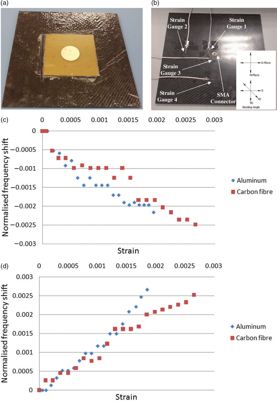
Figure 8. A circular microstrip patch antenna created on a carbon fibre composite plate for strain sensing(Reference Daliri, Galehdar, Rowe, Ghorbani and John146): (a) circular patch side (b) signal feed side (c) relationship between the strain and frequency shift at 0° (d) relationship between the strain and frequency shift at 90°.
Shi et al.(Reference Shi, Rathod, Mukherjee, Udpa and Deng147) designed a low-cost near-field microwave imaging system to estimate very large deformation of dielectric materials. The probe was an open-ended coaxial line with an extended copper tip, operating over a narrow frequency range around 7GHz. In the experiment, the probe tip was placed perpendicular to a polyamide 11 (PA-11) sheet. The microwave responses were correlated to the DIC measurement data for plastic strain in the range of 0.3-0.7. It was demonstrated that this method could be an alternative measurement modality.

Figure 9. Microwave inspection of delamination in a GFRP T-joint(Reference Li, Haigh, Soutis, Gibson and Sloan67): (a) illustration of the experimental setup (b) phase image produced at 19GHz.
4.4 Damage detection
Impact damage: Greenawald et al.(Reference Greenawald63) detected impact damage and holes in 42.5mm thick GFRP sandwich composites using three microwave bands: K band (18.0–26.5GHz), Ka band and V band. The sample subjected to a 1,204J impact was scanned on the non-impacted side. It was shown that the impact damage was best revealed at 25GHz with a standoff distance of 0.5mm.
Cracks and fibre breakage: Albishi et al.(Reference Albishi and Ramahi148) detected cracks in a fibreglass composite sample using a complementary split-ring resonator (CSRR) sensor. For a crack with a width of 200 $\upmu$m and a depth of 1.5mm, a maximum frequency shift of more than 312MHz was observed with respect to a reference case. Matsuzaki et al.(Reference Matsuzaki, Melnykowycz and Todoroki149) developed a self-sensing antenna for damage detection, where CFRP structures were modelled as half-wavelength dipole antennas. The feasibility was investigated analytically and experimentally using unidirectional CFRP laminates and rotor blades of woven CFRP. Signals were fed to the CFRP with electrodes mounted on the specimen surface. Wireless measurement were carried out with the CFRP as the transmitter and an aluminium dipole antenna as the receiver. The damage was introduced 80mm from the outer edge of the specimen by three-point bending. The resonance frequency of the CFRP antenna increased due to the shortened effective length of the antenna. The frequency change can be monitored wirelessly at a remote location, and the damage location can be estimated by comparing the frequency with that of an intact specimen.
Delamination/disbond: Hosoi et al.(Reference Hosoi and Ju66) used a K-band waveguide adaptor to detect slits (0.2, 0.5, 1.0 and 3.0mm wide), fluorine and aluminium films (20µm thick) inserted in E-glass fibre composite laminates. The aluminium film was detected at 18 and 26GHz, where the incident signal was reflected on the conductive surface and the presence of the film was better indicated by the phase variation. However, the fluorine film was not detected at both frequencies due to the low-loss characteristic and the small thickness.
Li et al.(Reference Li, Haigh, Soutis, Gibson and Sloan67) detected delamination in GFRP T-joints of wind turbine blades using an open-ended K-band waveguide. The experimental setup is illustrated in Fig. 9(a). The waveguide assembly was mounted on an X-Y-Z scanning stage and connected to an HP 8720D vector network analyser (VNA) by a semi-rigid coaxial cable. The inspection was conducted at a standoff distance of 5mm, and 26.56mm long delamination at the depth of approximately 3.82mm was identified in the phase image as shown in Fig. 9(b). In addition, from the electromagnetic simulation it was found that the highest detection sensitivity was recorded at 26GHz and a smaller standoff distance could significantly improve the performance.
Li et al.(Reference Li, Zhou, Lei and Pei150) used both a coaxial line and an antenna to examine defects in a GFRP composite plate with hat stiffeners. 0.4mm hole, 0.5 and 1mm inclusions and 0.1mm thick debonding were detected by the coaxial probe with high spatial resolution (0.4mm). Internal defects of poor resin infusions in the hat stiffener were detected by the pyramidal horn antenna with high penetration (over 100mm). With the combination of the two imaging methods, 95% of the scan imaging time was saved for the detection of the fibre wrinkling defects. A full-size image of the large stiffened plate was generated using the feature-based image stitching post-processing technique.
Navagato et al.(Reference Navagato and Narayanan151) developed an ultra-wideband (UWB) radar system, where noise waveforms were used. The performance was comparable with that by Gaussian-modulated sinusoidal pulses and linearly frequency-modulated chirp signals. An X-band (8–12GHz) imaging system was designed to detect impact damage in a CFRP sample. The impact damage was produced with a hammer, which was dropped with the head facing downwards. In the detection the standoff distance was set to 12cm, where the sample was in the Fresnel region of the horn antenna. In the image produced, the impact regions were distinguishable and corresponded to the dimensions of the hammerhead.
Lightning strike: Rufail et al.(Reference Rufail, Laurin and Moupfouma71) designed a microwave microscopy system for the evaluation of lightning strike protection (LSP) mesh on CFRP. The probe was an open-ended CPW transmission line, where a 1mm wide centre strip was separated by a 152µm narrow gap from two ground planes. The probe, coaxial cable and tuner formed a Fabry Perot resonator. The sample under test was a 4mm thick CFRP panel, on which an expanded copper foil (ECF) was installed. The top surface of the ECF was coated with 300µm of non-conductive paint layers and partially sanded to expose part of the LSP. During scanning the standoff distance was kept at 76μm. The difference in the conductivity between CFRP and copper mesh detuned the resonant frequency of the resonator. Flaws in the mesh and the locations were identified from the resonant frequency shift.
5.0 TRENDS
5.1 Advanced signal post-processing
It can be seen that most of the work carried out was focused on detecting the presence of damage or evaluating a few types of manufactured defects/damage. However, during fabrication or in service various types of defects/damage can be observed in one component, so research on identifying more types of damage from the inspection results is needed. Signal processing algorithms (e.g. principal component analysis (PCA) and support vector machine (SVM)) can be used for feature extraction and classification/prediction.
So far only simplistic data processing is applied. For example, in some cases the raw magnitude or phase data were examined for anomalies. For future research, artificial intelligence, big data and data science can be considered for the processing of the measurement data to achieve enhanced quality checking and fault diagnosis. Some work was done in the microwave detection of cracks in metals(Reference Ali, Albasir and Ramahi152-Reference Shrifan, Akbar and Isa154), while little has been reported on composite materials. Hence, the potential for intelligent microwave inspection is to be explored.
5.2 Intelligent heating using advanced solid-state technology
Over the last few years, with advances in semiconductors, it has become possible to generate microwave power of up to some hundred watts(155), so the power required for heating applications can now be achieved. The solid-state devices are bringing exceptional precision, advanced control, reliability and convenience compared with the common 2.45GHz magnetrons, which are based on vacuum tube technology. For example, it supports accurate power control over the full dynamic range, enabling frequency shifting that helps make precise use of the energy. The frequency and phase can be shifted to move nodes and anti-nodes within the cavity. The intensity of the input signal can also be dynamically changed according to the heating performance, forming a closed-loop control system.

Figure 10. Photograph of the automated inspection platform (in the red box) attached on the cabin surface of an AIRBUS A350(Reference Gray, Padiyar, Petrunin, Raposo, Fragonara, Kostopoulos, Loutas, Psarras, Sotiriadis, Tzitzilonis, Dassios, Exarchos, Matikas, Andrikopoulos and Nikolakopoulos157).
5.3 Automated inspection
Most of the microwave damage detection addressed was at the laboratory level. The specimens were usually flat, and tests were done either manually or on an X-Y-Z scanning platform. More work on instrumentation can be done to suit the real curved aircraft structures. From the perspectives of efficiency and safety, robots can be combined with microwave testing techniques to perform inspection, thereby reducing the downtime of the aircraft and relieving human inspectors from potentially dangerous situations(Reference Heuer, Schulze, Pooch, GÄbler, Nocke, Bardl, Cherif, Klein, Kupke, Vetter, Lenz, Kliem, BÜlow, Goyvaerts, Mayer and Petrenz52,Reference Brinker and Zoughi156) .
Gray et al.(Reference Gray, Padiyar, Petrunin, Raposo, Fragonara, Kostopoulos, Loutas, Psarras, Sotiriadis, Tzitzilonis, Dassios, Exarchos, Matikas, Andrikopoulos and Nikolakopoulos157) developed a robotic platform (shown in Fig. 10) for automated inspection using combined infrared thermography and phased array ultrasonics for the evaluation of near-surface and subsurface damage. The robot can remain attached to the inspected surface with a vortex-based actuation system. It can also transfer the inspection and repair equipment to the area of interest. The information provided by the two methods was fused for more accurate damage localisation. The robot system also consisted of a material removal module and a patch placement module. The material removal was done with a laser, which can precisely remove the material ply-by-ply. Thus, autonomous access, scan and repair was enabled.
In recent years there have been growing interests in the use of unmanned aerial vehicles (UAVs)/drones(Reference Dahlstrom158,Reference Rodriguez, Castiblanco, Mondragon and Colorado159) . For example, EasyJet airline engineers employed drones to perform automated visual inspection(160,Reference Bogue161) . Engineers of Austrian Airlines also experimented with UAVs for structural inspection(Reference Aamir162). It was claimed that the inspection time was greatly reduced to less than 2h per aircraft instead of 4–10h with manual checks. A drone flew around an aircraft’s exterior autonomously using laser technology and took a high-resolution image every second. The images were then used to work with accompanying software, and paint and structural damage could be automatically identified.
5.4 Digital twinning
Post COVID-19 the economic pressures on airline companies are going to ramp up due to the reduced demands for international travels. It is therefore essential that the cost of maintenance and replacement parts is minimised; rapid, accurate scanning of aircraft composite parts will give the confidence to extend the working life. The aircraft industry is leading in the industry 4.0 evolution to optimise the maintenance and replacement schedules. The so-called digital twin provides a complete model of an in-service aircraft. The current issue is that the digital twin needs accurate data about the physical conditions of the aircraft parts(Reference Thayer163). The microwave sensing methods reviewed here can help provide the required data to enable an effective digital twin. Data fusion techniques can be incorporated for improved decision making(Reference Liu, Meyendorf and Mrad164).
6.0 CONCLUDING REMARKS
The paper has addressed research during the past two decades on applications of microwave energy for fibre-reinforced polymer composites, covering heating (curing, 3D printing, joining and recycling) and sensing (measurement of permittivity and thickness, monitoring of cure state and fibre direction, and detection of air voids and damage). It has been demonstrated that microwaves can be potentially used in various stages of the life cycle of aircraft composite structures. Limitations of the existing microwave methods have been pointed out, and some trends that could be considered in future applications are discussed.
ACKNOWLEDGEMENTS
This work was financially supported by the Fundamental Research Funds for the Central Universities (Grant No. NS2020019), the Natural Science Foundation of Jiangsu Province (Grant No. SBK2020044527) and the Shuangchuang Project of Jiangsu Province (Grant No. KFR20020). The first author gratefully acknowledges valuable discussions with Dr. Matthieu Gresil from The University of Manchester.