


1. Introduction
Micro/nano patterning has been widely used in the manufacturing of integrated circuits, optical devices and biomedical sensors (Bonn et al. Reference Bonn, Eggers, Indekeu, Meunier and Rolley2009; Li et al. Reference Li, Ding, Shao, Tian and Liu2012, Reference Li, Tian, Shao, Ding, Chen, Wang and Lu2016; Lind et al. Reference Lind, Busbee, Valentine, Pasqualini, Yuan, Yadid, Park, Kotikian, Nesmith and Campbell2017). Among the many techniques for the fabrication of patterned micro/nano structures is thermocapillary patterning (Schäffer et al. Reference Schäffer, Harkema, Roerdink, Blossey and Steiner2003; Trice et al. Reference Trice, Favazza, Thomas, Garcia, Kalyanaraman and Sureshkumar2008; Rodríguez-Hernández Reference Rodríguez-Hernández2015; Singer Reference Singer2017). By this method, an initially flat polymer/air film is sandwiched between a hot substrate and a cold topographic template (figure 1a). This configuration allows a transverse thermal gradient to be generated along the polymer/air interface. Driven by the thermal gradient, the polymer flows towards the protrusion part, thereby resulting in the deformation of the film that conforms with the template. Periodic micro/nano structures are obtained upon the solidification of the deformed polymer film.

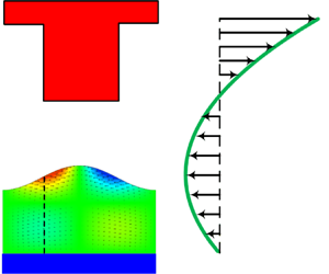
Figure 1. Thermocapillary patterning: (a) schematic representation of the system configuration and (b) computational domain for equilibrium deformation of the polymer film.
While early study attributes the above deformation to radiation pressure caused by coherent reflections of acoustic phonons (Schäffer et al. Reference Schäffer, Harkema, Roerdink, Blossey and Steiner2003), recent theoretical and experimental studies indicate that the thermocapillary force rather than the radiation pressure is responsible for the pattern formation (Dietzel & Troian Reference Dietzel and Troian2009; McLeod, Liu & Troian Reference McLeod, Liu and Troian2011). The mechanism was confirmed by Saprykin et al. (Reference Saprykin, Trevelyan, Koopmans and Kalliadasis2007), who have studied the thin film flows over a uniformly heated topography. The temperature along the polymer/air interface is non-uniform due to the modulation of the structured template (top plate). The surface tension depends on the temperature and is thus also non-uniform. Driving by the non-uniform surface tension, tangential flow occurs and leads to the deformation of the polymer film. The final micro/nano structures conform with the template, thus thermocapillary patterning can be considered as a replication technique. Different structures, such as periodic strips and prisms, have been obtained in experiments with thermocapillary patterning, by tuning the topology of the template, film thickness and other process parameters (Schäffer et al. Reference Schäffer, Harkema, Roerdink, Blossey and Steiner2003).
If the top template is also flat, then the perturbations on the polymer/air interface may lead to instability, which is usually referred to as thermocapillary instability. In this case, perturbations with a proper wavelength would be enlarged and result in the formation of micro/nano structures in the polymer film (Dietzel & Troian Reference Dietzel and Troian2009, Reference Dietzel and Troian2010; Nazaripoor et al. Reference Nazaripoor, Flynn, Koch and Sadrzadeh2018). With the thermocapillary instability, the film usually evolves into periodic micro-pillars. To predict the distance between two adjacent micro-pillars, linear stability analysis can be employed (Dietzel & Troian Reference Dietzel and Troian2009; Nazaripoor et al. Reference Nazaripoor, Flynn, Koch and Sadrzadeh2018). By this approach, a perturbation with a small amplitude and a given wavelength is imposed upon the initially flat polymer/air interface. The amplitude of perturbation is assumed to increase exponentially with time and the most unstable wavelength is calculated and treated as the distance between two adjacent micro-pillars. A distinctive advantage of patterning with the thermocapillary instability is that the flat template, compared with a topographical template, can be fabricated with ease. However, the periodicity of microstructures under a flat template is sensitive to the various parameters, e.g. temperature difference, film thickness and viscosity, making process control a rather challenging task. Consequently, in practice, a topographical template rather than a flat one is often used. The periodicity of microstructures can be well controlled by changing the topological configuration of the template.
So far, studies on thermocapillary patterning have been focused on the dynamic process of film flow and height evolution (Mukherjee & Sharma Reference Mukherjee and Sharma2015; Fiedler & Troian Reference Fiedler and Troian2016). In these studies, the fluid flow is usually approximated as one-dimensional flow and a tangential stress (i.e. the Marangoni stress) is imposed on the polymer/air interface to generate the flow. Moreover, a long-wave approximation (or the lubrication approximation) is employed to further simplify the calculation of the fluid flow and the thermal field. The final equations governing the evolution of interfacial morphology are solved with a proper numerical scheme (Nazaripoor et al. Reference Nazaripoor, Flynn, Koch and Sadrzadeh2018).
To the best of our knowledge, there appears to have been no equilibrium study (i.e. steady state) on thermocapillary patterning. In this paper, we present analytical and numerical models to investigate the equilibrium deformation of a polymer film under a transverse thermal gradient. The equilibrium state represents the deformation that the polymer film eventually evolves into and is of critical importance to fully appreciate the fundamentals governing the thermocapillary pattern formation process. A novel hysteresis phenomenon associated with the steady state thermocapillary patterning has not yet been discussed in dynamic processes. Moreover, a major difficulty in developing a steady state analysis of thermocapillary patterning is associated with the treatment of the polymer–template interface, (that is, where the polymer meets the template) where a common continuum mechanics approach breaks down because of a singularity associated with a jump condition inherent in the continuum mechanics description of a liquid–solid interface. Our analysis below will address this issue by introducing a molecular force remedy.
2. Problem statement
Let us now consider a typical system configuration of thermocapillary patterning as illustrated in figure 1(a), where the polymer/air film is spin coated on a hot substrate and a cold topographic template is placed above the film. This allows a spatially non-uniform temperature distribution to be produced along the polymer/air interface. If surface tension is temperature dependent, the resultant surface force will drive a tangential flow (i.e. the Marangoni flow) (Davis Reference Davis1987; Dietzel & Troian Reference Dietzel and Troian2010; Arshad et al. Reference Arshad, Kim, Prisco, Katzenstein, Janes, Bonnecaze and Ellison2014). To be specific, in the present configuration, the surface tension is larger under the protrusions because of a lower temperature there, while it is smaller in other areas. Hence, the portion of the polymer surface with a larger surface tension rises up, whereas that with a smaller surface tension trends downward, leading to a patterned deformation in the polymer film. As the deformation continues, the tangential flow starts to be impeded by the Laplace pressure gradient, and eventually the deformation process ceases because of the force balance on the polymer–air interface. In what follows, the governing equations for heat transfer and polymer film deformation are established and analyses are presented. For simplification, only one periodic structure is studied in this paper (figure 1b).
To obtain the temperature distribution along the film/air interface, some assumptions are made for the involved heat transfer process. The fluid flow in the film is of low Reynolds number, therefore the convection and transient terms in the heat transfer equations may be neglected (Ruyer-Quil et al. Reference Ruyer-Quil, Scheid, Kalliadasis, Velarde and Zeytounian2005; Scheid et al. Reference Scheid, Ruyer-Quil, Kalliadasis, Velarde and Zeytounian2005). The governing equation for heat transfer thus simplifies to a Laplace equation (i.e. the equation for steady conduction),  ${\nabla ^2}T = 0$, where T represents the temperature. Moreover, with a lubrication approximation (i.e. the periodic length is much larger than the film thickness,
  ${l_0} \gg {h_0}$) applied, the temperature distribution along the interface is obtained with the result,
 \begin{equation}T(x) = {T_h} - \frac{H}{{(1 - {k_r})H + {k_r}D}}\Delta T,\end{equation}
where  $H = h(x)/{h_0}$ and
  $D = d(x)/{h_0}$ denote the normalized height of polymer/air interface and the surface topology of template, respectively;
  ${k_r} = {k_p}/{k_a}$ is the relative thermal conductivity of polymer and air; and
  $\Delta T = {T_h} - {T_c}$ stands for the temperature difference. Due to the modulation of the template, the temperature along the polymer/air interface is non-uniform. As suggested by (2.1), the thermal field is one-dimensional and steady state. This is a direct result of the lubrication approximation (i.e. long-wave approximation). It is noteworthy that the approximation will be invalid if the film thickness is on the same scale as the periodic length.
The surface tension γ is assumed to be a linear function of temperature,  $\gamma = {\gamma _0} - \alpha [T - ({T_h} + {T_c})/2]$, where γ 0 represents the surface tension at the reference temperature
  ${T_0} = ({T_h} + {T_c})/2$, and α is a constant and represents the thermocapillary coefficient. In general, surface tension decreases with an increase in temperature and thus α is positive. The hydrostatic pressure inside the polymer film can be approximated as
  $p = {p_0} - \gamma {\nabla ^2}h$, with p 0 being the pressure of the air. Liquid motion can be considered as one-dimensional film flow and the polymer behaves as a Newtonian fluid with a constant viscosity μ. Also, the gravitational force is neglected in a micro/nano film. With these simplifications, the governing equations for the thin film flow can be written as
 \begin{equation}\left. {\begin{array}{*{20}{c@{}}} {0 ={-} \dfrac{{\partial p}}{{\partial x}} + \mu \dfrac{{{\partial^2}u}}{{\partial {y^2}}}},\\ {0 ={-} \dfrac{{\partial p}}{{\partial y}}}, \end{array}} \right\}\end{equation}
with the following boundary conditions,
 \begin{equation}\left. {\begin{array}{*{20}{c@{}}} {u = 0\quad \textrm{at}\;y = 0},\\ {\mu \dfrac{{\partial u}}{{\partial y}} = \dfrac{{\partial \gamma }}{{\partial x}}\quad \textrm{at}\;y = h}. \end{array}} \right\}\end{equation}
Integrating twice, one obtains the horizontal velocity u (Nazaripoor et al. Reference Nazaripoor, Flynn, Koch and Sadrzadeh2018; Fiedler, McLeod & Troian Reference Fiedler, McLeod and Troian2019),
 \begin{equation}u = \frac{1}{{2\mu }}\frac{{\partial p}}{{\partial x}}{y^2} - \frac{1}{\mu }\frac{{\partial p}}{{\partial x}}hy + \frac{1}{\mu }\frac{{\partial \gamma }}{{\partial x}}y,\end{equation}
that is, the velocity profile in the y-direction is described by a parabolic function. For the film flow, conservation of mass requires that
 \begin{equation}\frac{{\partial h}}{{\partial t}} ={-} \frac{\partial }{{\partial x}}\left( {\int_0^h {u\,\textrm{d}y} } \right).\end{equation}
Substituting u, γ, p and T into (2.5) and rearranging, one obtains the non-dimensionalized equation for the spatial-temporal evolution of the interface,
 \begin{equation}\frac{{\partial H}}{{\partial \tau }} + {\nabla _\parallel }\boldsymbol{\cdot} \left\{ {C{a^{ - 1}}\frac{{{H^3}}}{3}\nabla_\parallel^3H + Ma\frac{{{H^2}}}{2}\frac{{{k_r}(D{\nabla_\parallel }H - H{\nabla_\parallel }D)}}{{{{[(1 - {k_r})H + {k_r}D]}^2}}}} \right\} = 0,\end{equation}
where  $\tau = {u_c}t/{l_0}$ is the normalized time,
  ${u_c} = {h_0}{\gamma _0}/{l_0}\mu$ is the characteristic velocity, the capillary number
  $Ca = \mu {u_c}l_0^3/{\gamma _0}h_0^3$, and the Marangoni number
  $Ma\, = \,{h_0}\alpha \Delta T/{l_0}\mu {u_c}$. In this paper, we focus on the equilibrium state of the film deformation. At equilibrium, the interface stops evolving, namely
  $\partial H/\partial \tau = 0$. With this substituted into (2.6) and with allowance for a two-dimensional analysis, one has the following nonlinear equation governing the deformation of the interface,
 \begin{equation}\frac{{{H^3}}}{3}\frac{{{\textrm{d}^3}H}}{{\textrm{d}{X^3}}} + \Im \frac{{{H^2}}}{2}\frac{{{k_r}\left( {D\dfrac{{\textrm{d}H}}{{\textrm{d}X}} - H\dfrac{{\textrm{d}D}}{{\textrm{d}X}}} \right)}}{{{{[(1 - {k_r})H + {k_r}D]}^2}}} = {C_1},\end{equation}
where the non-dimensional parameter  $\Im \equiv Ma \, Ca = \alpha \Delta Tl_0^2/{\gamma _0}h_0^2$, and C 1 is a constant. With X = x/l 0 being the normalized coordinate, H(X) and D(X) are symmetric at X = 0 and X = 1, and thus
  $\textrm{d}H/\textrm{d}X = 0$,
  $\textrm{d}D/\textrm{d}X = 0$ and
  ${\textrm{d}^3}H/\textrm{d}{X^3} = 0$ at these two points. These constraints led to C 1 = 0.
3. Linear model
We first consider a linearized model for the equilibrium deformation of the liquid film. For linear analysis, D(X) and H(X) are decomposed into a Fourier series. All the high-order terms are neglected and only the first-order terms are retained,  $H(X) \approx 1 - {H_1}\cos (2{\rm \pi} X)$,
  $D(X) \approx {D_0} + 2/{\rm \pi} \Delta D\cos (2{\rm \pi} X)$. Substituting these linear terms into (2.7), the amplitude of the deformed polymer film H 1 can be obtained. In this paper, we use the structure height,
  $\Delta H = 2{H_1}$, to characterize the deformation of the polymer film. For a given set of parameters (ΔD, D 0, kr and
  $\Im$), the structure height ΔH is obtained, from (2.7), as,
 \begin{equation}\Delta H = \frac{{12\Delta D{k_r}}}{{8{{\rm \pi} ^3}{{(1 - {k_r} + {k_r}{D_0})}^2}{\Im ^{ - 1}} - 3{\rm \pi} {k_r}{D_0}}}.\end{equation}
For all analyses presented below, unless explicitly noted otherwise, the following parameters are fixed: ka = 0.036 W (m °C)−1, kp = 0.144 W (m °C)−1, h 0 = 100 nm, d 0 = 250 nm, Δd = 100 nm, l 0 = 2 μm, γ 0 = 31.53 mN m−1, T 0 = 150 °C, α = 88.5 μN (m °C)−1. For these values, the corresponding non-dimensional parameters are ΔD = 1, D 0 = 2.5, kr = 4.
Figure 2(a) depicts the dependence of structure height ΔH on  $\Im$. For
  $\Im > 0$, ΔH is positive, indicating that the deformation in the thin polymer film has a phase difference with the template structure (or positive replication). For
  $\Im < 0$, the polymer film has the same phase as the template (or negative replication). This is consistent with the experimental observations by Schäffer et al. (Reference Schäffer, Harkema, Roerdink, Blossey and Steiner2003). In the case of
  $\Im < 0$, either the surface tension of the polymer film increases with the temperature (α < 0), or the temperature difference is reversed (ΔT < 0). Under these circumstances, the deformation in the polymer film is small. For the limiting case of
  $\Im$ decreasing to minus infinity,
  $\Im \to - \infty$, the structure height ΔH approaches the limit
  $- 4\Delta D/{\rm \pi} {D_0} \approx{-} 0.5$. This means that the maximum structure height is
  $|\Delta H|= 0.5$ for a negative
  $\Im$.

Figure 2. Film deformation predicted by the linear model. (a) Dependence of structure height ΔH on the non-dimensional number  $\Im$. (b) Normalized velocity U = u/uc at non-equilibrium state and equilibrium state.
In practical experiments, the surface tension of a polymer film decreases with an increase in temperature (α > 0) and the temperature difference is kept positive (ΔT > 0). Therefore,  $\Im$ is larger than zero. Under this condition, the structure height ΔH increases with increasing
  $\Im$, as illustrated in figure 2(a). In the range of
  $0 < \Im < 50$, the film is slightly deformed. With a further increase of
  $\Im$, the film deformation becomes more pronounced. The structure height goes to infinity when the denominator in (3.1) equals zero. At this limit,
  $\Im$ is given by,
 \begin{equation}{\Im _c} = \frac{{8{{\rm \pi} ^2}}}{3}\frac{{{{(1 - {k_r} + {k_r}{D_0})}^2}}}{{{k_r}{D_0}}}.\end{equation}
This value can be considered as the critical value of  $\Im$. As
  $\Im$ approaches this critical value
  ${\Im _c}$, the film experiences a drastic deformation. This suggests that if a micro-pattern with a large deformation is to be obtained, the imposed
  $\Im$ should be equal to or larger than this critical value. For the parameter values given in this section, the critical value is
  ${\Im _c} = 128.96$, the corresponding ΔT = 115 °C (the other parameters are the default values).
For the equilibrium states of thermocapillary patterning, a question naturally arises: Is there any flow inside the polymer film, or in other words, is the fluid static? To answer this question, we calculated the velocity profile u by (2.4) and the results are plotted in figure 2(b), where U = u/uc is the normalized velocity. A positive value of the velocity indicates the flow is rightward and a negative value indicates it is leftward. Examination of (2.4) reveals that the flow field can be considered as a combination of Poiseuille flow (the first two terms) and Couette flow (the last term). For a pressure driven Poiseuille flow, the velocity profile follows a parabolic function  $(1/2\mu )(\partial p/\partial x){y^2} - (1/\mu )(\partial p/\partial x)hy$ (Cengel Reference Cengel2010). For a Couette flow, the velocity profile takes a linear function
  $({u_0}/h)y$, where u 0 is the velocity at the interface and h is the thickness of the film. By the force balance at the interface
  $(\partial \gamma /\partial x) = \mu ({u_0}/h)$, thus
  $({u_0}/h)y = (1/\mu )(\partial \gamma /\partial x)y$. Therefore, the flow in (2.4) can be decomposed into a Poiseuille flow and a Couette flow.
For the present case, the Couette flow essentially is induced by the transverse temperature gradient. The polymer film below the template protrusion has a lower temperature (and hence a larger surface tension) than the recess. The corresponding thermocapillary force drives the tangential flow and the moving interface drags the film towards the middle position of the protrusion. Polymer is accumulated at this position, thereby resulting in the deformation in the film. With the bulging up of the film, the hydrostatic pressure increases due to the pressure jump across the interface (i.e. the Laplace pressure). This pressure tends to push back the polymer and generates the reverse Poiseuille flow (back flow). When ΔH = 0, the Laplace pressure is negligibly small and the corresponding Poiseuille flow is zero. The flow is dominated by the Couette flow, and the velocity takes a linear profile. The film flows towards the centre (i.e. the position underneath the template protrusion). With the increase of deformation, the Laplace pressure at the centre increases and starts to impede the Couette flow driven by the thermocapillary force. At equilibrium state, the Couette flow is counterbalanced by the Poiseuille flow and the net flux is zero. The polymer near the interface tends to flow towards the centre point under the protrusion, and the polymer near the substrate flows away from the centre point (Saenz et al. Reference Saenz, Valluri, Sefiane, Karapetsas and Matar2013). The height of polymer film, however, ceases to evolve when the equilibrium is reached.
4. Nonlinear numerical model
In experiments, the deformation of the polymer film, rather than going to infinity, would be stopped by the template (or substrate) due to the geometric constraint. In the above linear model, the case of a polymer film contacting a template (or substrate) cannot be predicted. To describe the interaction of the film with the template, we developed an enhanced nonlinear numerical model by introducing the van der Waals molecular force between the polymer film and the top template (or bottom substrate),  $p = {p_0} - \gamma {\nabla ^2}h + A{(d - h)^{ - 3}} - A{h^{ - 3}}$, where A denotes the Hamaker constant (Wu, Pease & Russel Reference Wu, Pease and Russel2005; Wu & Russel Reference Wu and Russel2005; Yang, Li & Ding Reference Yang, Li and Ding2013). Physically, there are two repulsive molecular forces, one is between the polymer film and the top template, and other is between the polymer film and the bottom substrate. These repulsive forces essentially ensure that the polymer film is confined between the template and substrate. Theoretically, the van der Waals molecular force includes two components: the attractive (conjoining) force and repulsive (disjoining) force. Whether the attractive or repulsive component dominates the molecular force depends on the materials and substrate. In this paper, we ignore the attractive force and retain only the repulsive force. There are two reasons for this choice. First, in practical applications, the template is usually coated with a hydrophobic layer, e.g. Teflon or carbon tetrafluoride. The coating is to ease the removal of the template from the solidified polymer film. This coating layer has a low surface energy and tends to reduce the attractive force (and hence to increase the repulsive force) between the polymer film and the template. Second, the repulsive force helps to model the case when the polymer film starts to have contact with the plates. If the force is attractive, the polymer film would ‘penetrate’ into the template. It is worth noting that the repulsive molecular forces in similar forms are commonly adopted for modelling the deformation of polymer films (Wu et al. Reference Wu, Pease and Russel2005; Wu & Russel Reference Wu and Russel2006; Wu, Kavousanakis & Russel Reference Wu, Kavousanakis and Russel2010; Nazaripoor et al. Reference Nazaripoor, Koch, Sadrzadeh and Bhattacharjee2016, Reference Nazaripoor, Flynn, Koch and Sadrzadeh2018; Nazaripoor, Koch & Sadrzadeh Reference Nazaripoor, Koch and Sadrzadeh2017). The criterion for choosing the Hamaker constant (and hence the molecular force) is that the force is much smaller than other forces when the film is far away from the top and bottom plates. Thus, its presence will have no influence on the film deformation there. When the film approaches the top or bottom plate, the molecular force should be significant and large enough to prevent the ‘penetration’ of the liquid into the solid. For convenience, the two repulsive molecular forces (the one between polymer film and top template, and the one between polymer film and bottom substrate) are assumed to be the same. The governing equation at the equilibrium state, taking into account the presence of molecular forces, then becomes
 \begin{equation}\frac{{{H^3}}}{3}\frac{{{\textrm{d}^3}H}}{{\textrm{d}{X^3}}} + \Im \frac{{{H^2}}}{2}\frac{{{k_r}\left( {D\dfrac{{\textrm{d}H}}{{\textrm{d}X}} - H\dfrac{{\textrm{d}D}}{{\textrm{d}X}}} \right)}}{{{{[(1 - {k_r})H + {k_r}D]}^2}}} - \frac{{\bar{A}}}{3}\frac{\textrm{d}}{{\textrm{d}x}}\left[ {\frac{1}{{{{(D - H)}^3}}} - \frac{1}{{{H^3}}}} \right] = {C_2},\end{equation}
where  $\bar{A} = Al_0^2/{\gamma _0}h_0^4$ is a non-dimensional parameter which denotes the ratio between the repulsive molecular force and surface tension, and C 2 is a constant. In the results presented below,
  $\bar{A} = {10^{ - 4}}$ is used. The presence of the molecular forces does not alter the symmetry conditions on H(X) and D(X) and thus we have C 2 = 0.
In the numerical model, nonlinear terms for D(X) and H(X) are considered. The template is represented by  $D(X) = {D_0} + \Delta D[1/2 + \varepsilon (X - 3/4) - \varepsilon (X - 1/4)]$, where
  $\varepsilon$(X) is the step function. The above governing equation together with mass conservation equation,
  $\int_0^1 {H(X)\,\textrm{d}X} = 1$, is solved by the finite difference method. For a set of given parameters (kr, D 0, ΔD,
  $\Im$ and
  $\bar{A}$), the shape of the polymer film H(X) is obtained. As reported previously, the deformation of a liquid film under an external force could exhibit multiple equilibrium states (Yang et al. Reference Yang, Li, Tian, Li, Shao, Chen and Xu2016; Liu et al. Reference Liu, Ouchi, Jin, Hayward and Suo2019). Thus, we enhance the numerical model by the arc-length continuation method to trace the turning points associated with nonlinear phenomena (Thiele et al. Reference Thiele, Velarde, Neuffer and Pomeau2001, Reference Thiele, Neuffer, Pomeau and Velarde2002, Reference Thiele, Brusch, Bestehorn and Bär2003; Merkt et al. Reference Merkt, Pototsky, Bestehorn and Thiele2005; Yang et al. Reference Yang, Li, Tian, Li, Shao, Chen and Xu2016).
The nonlinear numerical results are illustrated in figure 3(a). When the deformation is small, the results are consistent with the linear analyses. For a large deformation, the nonlinear effects come into play and the discrepancy between the linear and nonlinear models becomes pronounced. Compared with the nonlinear results, the linear model tends to underpredict the deformation. One intriguing phenomenon of the nonlinear result is that the structure height ΔH does not monotonically increase with  $\Im$. The
  $\Im \sim \Delta H$ curve takes an ‘S’ shape, and there exist two turning points B and D on the curve. When the deformation is at point B (
 $\Im = 70.9$, ΔH = 1.32), a slightly increase of
  $\Im$ will lead to a significant increase in ΔH. It jumps from point B to C (
 $\Im = 70.9$, ΔH = 1.96). At this instance, the polymer film is in contact with the top template (figure 3b). The film cannot penetrate the template due to the presence of the repulsive molecular force between the film and the template. The value,
  ${\Im _{c,1}} = 70.9$, is referred to as the first critical value in our analysis. Thus, if microstructures with a large deformation in the polymer film are to be obtained, then the patterning process parameters must be chosen such that
  $\Im$ exceeds this critical value. If
  $\Im$ is further increased above
  ${\Im _{c,1}}$, the polymer film spreads along the surface of the template, forming the topological feature of the template. Meanwhile the residual film on the substrate is reduced in thickness and the structure height ΔH is increased slightly. The maximum structure height is
  ${D_0} - \Delta D/2 = 2$, and the polymer film, at this point, bridges the template and substrate.

Figure 3. Film deformation predicted by the nonlinear numerical model. (a) The dependence of structure height ΔH on the non-dimensional number  $\Im$. (b) Some representative results of film deformation. When increasing or decreasing
  $\Im$, the polymer film may undergo different deformations.
At this point when the polymer film is in touch with the top template, the value of  $\Im$ is gradually reduced. The polymer film remains attached to the template until ℑ decreases to the second critical value
  ${\Im _{c,2}} = 67.4$. With
  $\Im$ further decreased, the system would jump from point D (
 $\Im = 67.4$, ΔH = 1.86) to A (
 $\Im = 67.4$, ΔH = 0.86), and the polymer film detaches from the template there after (figure 3b). Since
  ${\Im _{c,1}} \ne {\Im _{c,2}}$, one can see that there appears to be a hysteresis phenomenon in the liquid film deformation. In essence, a large
  $\Im$ is required to obtain microstructures with a large deformation and a relatively smaller
  $\Im$ is sufficient to retain the deformation. In passing, we note that the hysteresis phenomenon is frequently encountered in nonlinear systems. Hysteresis deformation of droplets in an electric and/or magnetic field (Sherwood Reference Sherwood1988; Song et al. Reference Song, Ju, Fan, Chen and Yang2019) and in moving droplets (Savva & Kalliadasis Reference Savva and Kalliadasis2009, Reference Savva and Kalliadasis2011) are some of the reported studies.
The system parameters, e.g.  $\bar{A}$, kr and D 0, may also affect the deformation of the polymer film. As indicated in figure 4(a), if the Hamaker constant is zero (
 $\bar{A} = 0$), i.e. in the absence of van der Waals molecular force, a steady state cannot be obtained for
  $\Im > {\Im _c}$. The molecular force is short range in nature, and thus has little influence on the fluid behaviour away from the liquid–solid interface. This is confirmed by the result that the
  $\Im \sim \Delta H$ curves coincide when the film is far away from the template (the deformation is small) for different values of
  $\bar{A}$. However, the value of
  $\bar{A}$ would significantly affect the film deformation near the template. In this paper, the value
  $\bar{A} = {10^{ - 4}}$ was used. If a smaller
  $\bar{A}$ were to be used, more computing time would be required to obtain converged results. It is found that a further decrease of the value of
  $\bar{A}$ does not affect the film deformation much, thus
  $\bar{A} = {10^{ - 4}}$ was chosen for the present studies.

Figure 4. Effect of parameters on the film deformation. (a) The effect of  $\bar{A}$ on the structure height. (b) The effect of kr on the structure height. (c) The effect of D 0 on the structure height. (d) The highest and lowest points for different D 0. (e) Dependence of
  ${\Im _{c,1}}$ and
  ${\Im _{c,2}}$ on kr and D 0.
Figure 4(b) illustrates the effect of kr on the  $\Delta H\sim \Im$ deformation curve. With
  $\Im$ kept the same, a larger kr results in a smaller structure height. This is because a larger kr corresponds to a higher thermal conductivity of the polymer. For the present case, the polymer film is coated onto a flat substrate with a constant temperature, and a larger kr allows heat transfer through the film to proceed more quickly, therefore the temperature distribution along the polymer/air interface becomes more uniform. As discussed before, the deformation in the polymer film is essentially caused by the non-uniform temperature along the interface. Therefore, a larger kr leads to a smaller deformation. As to the effect of template–substrate distance D 0, a smaller D 0 indicates that template is closer to the polymer/air interface, and thus results in a stronger modulation on the temperature (figure 4c). The highest and lowest points are depicted as a function of D 0 in figure 4(d). For D 0 = 2.5, the polymer film is still in contact with the bottom substrate when it reaches the top template. For D 0 = 2, the film reaches the template before it contacts the substrate. As to the cases of D 0 = 3 and D 0 = 3.5, the film contacts the substrate first. With a further increase of
  $\Im$, the highest point of polymer film continues increasing.
By changing D 0, it is found that the hysteresis phenomenon may disappear for small D 0. For most cases, there exist two critical values of  $\Im$, and
  ${\Im _{c,1}} \ne {\Im _{c,2}}$. In some instances, the structure height ΔH monotonically increases with an increase of
  $\Im$ (i.e. no hysteresis). To further understand the influence of D 0 and kr on the hysteresis phenomenon, the values of
  ${\Im _{c,1}}$ and
  ${\Im _{c,2}}$ are monitored and plotted as a function of D 0 in figure 4(e). Clearly, with D 0 decreasing,
  ${\Im _{c,1}}$ and
  ${\Im _{c,2}}$ collapse to the same value, and the hysteresis phenomenon would therefore disappear. By comparing the results of different kr in figure 4(e), one can see that the hysteresis disappears at a larger D 0 for kr = 1, and it disappears at a smaller D 0 for kr = 8.
5. Lyapunov functional
The evolution of polymer film topology may be explained from the viewpoint of the energy in the deformation system (Thiele et al. Reference Thiele, Velarde, Neuffer and Pomeau2001, Reference Thiele, Neuffer, Pomeau and Velarde2002, Reference Thiele, Brusch, Bestehorn and Bär2003; Merkt et al. Reference Merkt, Pototsky, Bestehorn and Thiele2005; Dietzel & Troian Reference Dietzel and Troian2009, Reference Dietzel and Troian2010; Yang et al. Reference Yang, Li, Tian, Li, Shao, Chen and Xu2016). For the system under study, its governing equation, i.e. (2.6), is essentially a generalized Cahn–Hilliard-type equation. Consequently, we can construct a Lyapunov free energy functional (Dietzel & Troian Reference Dietzel and Troian2009, Reference Dietzel and Troian2010),
 \begin{align}F &= \int_0^1
{{{(\boldsymbol{\nabla }H)}^2}} - \frac{{3\Im
}}{{{k_r}D}}\left[ {H\ln \left( {\frac{{{k_r}DH}}{{{k_r}D +
(1 - {k_r})H}}} \right) + \ln \left( {1 + \frac{{1 -
{k_r}}}{{{k_r}D}}} \right)} \right]\notag\\ &\quad + \bar{A}\left[
{\frac{1}{{{H^2}}} + \frac{1}{{{{(D - H)}^2}}}}
\right]\,\textrm{d}X.\end{align}
\begin{align}F &= \int_0^1
{{{(\boldsymbol{\nabla }H)}^2}} - \frac{{3\Im
}}{{{k_r}D}}\left[ {H\ln \left( {\frac{{{k_r}DH}}{{{k_r}D +
(1 - {k_r})H}}} \right) + \ln \left( {1 + \frac{{1 -
{k_r}}}{{{k_r}D}}} \right)} \right]\notag\\ &\quad + \bar{A}\left[
{\frac{1}{{{H^2}}} + \frac{1}{{{{(D - H)}^2}}}}
\right]\,\textrm{d}X.\end{align}
The first term on the right-hand side of the above equation characterizes the energy density associated with interfacial curvature, and its effect is to flatten the film and prevent the deformation. The second term accounts for the Marangoni effect, which tends to drive the initially flat film into ‘two phases’: a thicker film and a thinner film. The third term represents the energy density associated with the molecular forces. The third term becomes significant when the polymer/air interface is in close proximity to the template or substrate. If we drop the third term (i.e. molecular force) and treat D as a constant, (5.1) would simplify to the form given by Dietzel & Troian (Reference Dietzel and Troian2009, Reference Dietzel and Troian2010).
The process of thermocapillary patterning is to minimize the Lyapunov free energy, and the equilibrium state corresponds to the minimum of the functional. For a set of given parameters (D(X), kr,  $\Im$ and
  $\bar{A}$), the free energy F is a function of H(X). For
  $\Im < {\Im _{c,2}}$, the free energy first decreases and then increases, with the film deformation ΔH increasing (figure 5a). There appears one minimum of free energy (point P) which corresponds to the equilibrium state. For
  ${\Im _{c,2}} \le \Im \le {\Im _{c,1}}$, the free energy F takes the form of a double well function (figures 5b and 5c). In this case, there are two local minima (points P and Q) and one maximum (point O) of free energy, which correspond to three equilibrium states. From figure 3(a), one can see that, for a given
  $\Im \in [{\Im _{c,2}},\;{\Im _{c,1}}]$, there are three equilibrium states. One state lies in the segment A–B, another in B–D and the third in D–C. Each equilibrium state corresponds to the point P, O or Q on the free energy curve, respectively. The solution in segment B–D corresponds to the local maximum of free energy. This state is unstable and thus physically impossible to realize in experiments. As for the two equilibrium states in segments A–B and D–C, one of them is stable and the other is metastable, depending on which state has the lower free energy. For
  $\Im > {\Im _{c,1}}$, only one equilibrium state is observed (point P in figure 5d). The corresponding deformation ΔH ≈ 2 indicates that the polymer/air interface ‘bridges’ the template and substrate.

Figure 5. Lyapunov free energy F( $\Im$, ΔH), given by (5.1) with the following parameters ΔD = 1, D 0 = 2.5, kr = 4 and
  $\bar{A} = {10^{ - 4}}$; (a)
  $\Im < {\Im _{c,2}}$, (b,c)
  ${\Im _{c,2}} \le \Im \le {\Im _{c,1}}$, (d)
  $\Im > {\Im _{c,1}}$. Points O, P, Q represent the local maximum or minimum free energy associated with thermocapillary deformation.
6. Discussion
In experiments, usually micro/nano patterning with a large deformation is favourable. Thus  $\Im$ should be larger than
  ${\Im _{c,1}}$. The numerical results computed with the model presented here may be compared with the experiments performed by Schäffer et al. (Reference Schäffer, Harkema, Roerdink, Blossey and Steiner2003). In their experiments, liquid polystyrene with an average molecular weight 108 kg mol−1 was used as the polymer film, and the process parameters were set as h 0 = 106 nm, Th = 171 °C and Tc = 133 °C. The thermophysical properties used are: the reference surface tension γ 0 = 31.53 mN m−1, thermocapillary coefficient α = 88.5 μN (°C)−1, thermal conductivity ka = 0.036 W (m °C)−1 and kp = 0.13 W (m °C)−1 (Mark Reference Mark2009; Fiedler et al. Reference Fiedler, McLeod and Troian2019). The structure height of the template was not measured in the experiments, and we assume it equals the film thickness d = h 0. In their first experiment, d = 160 nm, l 0 = 2 μm and
  $\Im = 37.97$ (experiment); with these parameters
  ${\Im _{c,1}} = 31.18$ was calculated using our numerical model. In the second experiment, d = 190 nm, l 0 = 4 μm and
  $\Im = 151.88$ (experiment);
  ${\Im _{c,1}} = 95.93$. In the third experiment, d = 220 nm, l 0 = 6 μm and
  $\Im = 341.74$ (experiment);
 ${\Im _{c,1}} = 104.95$. Thus the imposed
  $\Im$ values in the three experiments all exceeded the critical
  ${\Im _{c,1}}$ and ensured the large deformation in polymer film.
In this paper, we assumed the polymer behaves as a Newtonian fluid with a constant viscosity. However, the results are also applicable to a non-Newtonian fluid. At equilibrium state, the deformation is governed by (2.7) (linear model) or (4.1) (nonlinear model). The viscosity does not come into play in the governing equations. The value of viscosity has no influence on the equilibrium deformation. What the viscosity affects is the time scale, i.e. how long it takes for the film to achieve its equilibrium state of deformation. However, the viscosity would affect the fluid flow, as indicated by (2.4). Thus the velocity profiles in figure 2(b) would be different if the viscosity is considered as a variable of temperature and shear stress.
In a previous study (Yang et al. Reference Yang, Li, Tian, Li, Shao, Chen and Xu2016), we have investigated the equilibrium deformation of electrohydrodynamic patterning. A polymer/air film is sandwiched between a flat plate and a topological plate, with an external electric field imposed between the two plates. A similar hysteresis deformation is also observed in electrohydrodynamic patterning. However, there are some critical differences between electrohydrodynamic patterning and thermocapillary patterning. First, the driving force is different, one is electrical whereas the other is the thermocapillary force. The direction of electrical force is applied normally to the polymer/air interface (for perfect dielectric materials) while the Marangoni force is tangential to the polymer/air interface. Second, there is no fluid flow in electrohydrodynamic patterning when deformation reaches an equilibrium state. In contrast, for thermocapillary patterning, fluid flow exists inside the polymer film at equilibrium state (see figure 2b).
7. Concluding remarks
In this paper, we developed linear and numerical nonlinear models to study the equilibrium states of thermocapillary patterning. From the theoretical analysis and numerical simulations, the following conclusions are obtained.
Both linear and nonlinear results indicate that equilibrium deformation exists during thermocapillary patterning of liquid films. At an equilibrium state, the structure height ceases evolving, and yet there is fluid flow inside the film. Near the film/air interface, the film flows towards the side with a large surface tension, and the flow is reversed near the bottom substrate, with a zero net flow rate. The model analyses reveal that the deformation of a polymer film is dependent on the non-dimensional parameter  $\Im \equiv Ma \cdot Ca$. There exists a critical value of
  $\Im$, above which the polymer film experiences a drastic deformation.
The nonlinear model uncovers a hysteresis in thermocapillary deformation of liquid films. When  $\Im$ approaches the first critical value
  ${\Im _{c,1}}$, the structure height increases drastically until the film touches the top template. Once in contact, a relatively smaller
  $\Im$ is sufficient to maintain the deformation of the polymer film. The polymer film does not detach itself from template until
  $\Im$ decreases to the second critical value
  ${\Im _{c,2}}$ (usually
  ${\Im _{c,1}} > {\Im _{c,2}}$).
According to the nonlinear model, there is only one equilibrium deformation state for either  $\Im < {\Im _{c,2}}$ or
  $\Im > {\Im _{c,1}}$. However, three equilibrium states are possible for
  ${\Im _{c,2}} \le \Im \le {\Im _{c,1}}$. By studying the Lyapunov free energy of the thermocapillary patterning, it is found that, of the three equilibrium states, one is stable, the other is metastable and the third is unstable.
Funding
The work was financially supported by the National Natural Science Foundation of China (51911530694, 11972280), the Key Research and Development Program of Shaanxi (2021GY-294), the Zhejiang Provincial Natural Science Foundation of China (LQ21E050009) and Beilin District Applied Technology Research and Development Projects in 2020 (GX2027).
Declaration of interests
The authors report no conflict of interest.


