


1 Introduction
The formation of liquid slugs in gas-filled channels or gas bubbles in liquid-filled channels can be detrimental for multiphase fluid systems aboard spacecraft and small-scale fluidic devices on Earth. This is particularly the case when pressure driving forces for channel flow are small, such as when they depend on capillary pressure differences or small manifold pressure differences in parallel-channel devices. Water slugs in air channels on the cathode side of a fuel cell can cause channel blockage that reduces fuel cell performance (Zhang, Yang & Wang Reference Zhang, Yang and Wang2006; Cheah, Kevrekidis & Benziger Reference Cheah, Kevrekidis and Benziger2013). Similarly, carbon dioxide bubbles in liquid fuel channels on the anode side of a micro direct methanol fuel cell (
 $\unicode[STIX]{x03BC}$
DMFC) have been found to block channels and reduce performance (Litterst et al.
Reference Litterst, Eccarius, Hebling, Zengerle and Koltay2006; Liang et al.
Reference Liang, Luo, Zheng and Wang2017). Bubbles trapped in the arterial wick of a heat pipe interrupt the transport of the heat carrier fluid to the evaporator zone, adversely affecting performance (Schlitt Reference Schlitt1994; Faghri Reference Faghri1995). A channel shape can be chosen to prevent channel blockage for a fluid segment with given wetting characteristics.
$\unicode[STIX]{x03BC}$
DMFC) have been found to block channels and reduce performance (Litterst et al.
Reference Litterst, Eccarius, Hebling, Zengerle and Koltay2006; Liang et al.
Reference Liang, Luo, Zheng and Wang2017). Bubbles trapped in the arterial wick of a heat pipe interrupt the transport of the heat carrier fluid to the evaporator zone, adversely affecting performance (Schlitt Reference Schlitt1994; Faghri Reference Faghri1995). A channel shape can be chosen to prevent channel blockage for a fluid segment with given wetting characteristics.
The specific geometry of study in this work is the eccentric annulus between an outer tube and inner rod originally studied by Smedley (Reference Smedley1990). This has the advantage of wedge-shaped regions within a circular conduit that is simple to construct. This geometry has been used in making microelectrode or microinjection pipettes by annealing a small glass rod to the inner wall of the tubing. Without this glass filament, back-filling pipettes can become difficult, often leading to slow filling or blockage of the pipette by an air bubble (Oesterle Reference Oesterle2015). A very similar geometry to the eccentric annulus is the vane gap configuration which is common in vane-type liquid propellant management devices in microgravity. The gap between the vane and the wall must be sufficiently small to create the necessary wicking flows (Chen & Collicott Reference Chen and Collicott2006).
Finn (Reference Finn1983) extended the criterion of Concus & Finn (Reference Concus and Finn1969) and developed the general existence/non-existence occlusion criterion for cylinders of arbitrary cross-sectional shape under weightlessness. Smedley (Reference Smedley1990) applied the method of Finn (Reference Finn1983) to the case of an annular geometry, which is topologically different from the cylindrical geometry for which the method was originally derived. Smedley considered a wetting fluid in the eccentric annulus between two non-concentric cylinders and presented the critical values of geometric parameters at which the transition from occluding to non-occluding configurations occurred for wetting angles from
 $1^{\circ }$
to
$1^{\circ }$
to
 $85^{\circ }$
.
$85^{\circ }$
.
Several researchers have studied the equilibrium configuration of a minority phase, like a bubble in a liquid-filled channel or a drop in a gas-filled channel. Collicott, Lindsley & Frazer (Reference Collicott, Lindsley and Frazer2006) studied the equilibrium shape of liquid volumes in a circular rigid tube of gas in the absence of gravity for various contact angles and volumes. They examined three static equilibrium topologies: an annulus, an occluding plug and a wall-bound drop. They found that the drop topology is the stable solution at the smallest volumes; the plug is stable for the larger volumes; and the annulus is the low-energy solution only for one small region near contact angles less than approximately
 $21^{\circ }$
for a range of volumes. Heil (Reference Heil1999) investigated the existence and stability of static liquid bridges in non-axisymmetrically buckled elastic tubes. It was found that, for a wide range of control parameters, the compressive forces generated by the liquid bridge are strong enough to hold the elastic tube in a buckled configuration. The minimum volume of liquid required to form an occluding liquid bridge in such tubes was also found.
$21^{\circ }$
for a range of volumes. Heil (Reference Heil1999) investigated the existence and stability of static liquid bridges in non-axisymmetrically buckled elastic tubes. It was found that, for a wide range of control parameters, the compressive forces generated by the liquid bridge are strong enough to hold the elastic tube in a buckled configuration. The minimum volume of liquid required to form an occluding liquid bridge in such tubes was also found.
Concus & Finn (Reference Concus and Finn1969) first investigated the behaviour of a liquid that partially fills a wedge-shaped container. They showed that, when the critical geometric wetting condition is satisfied,
 $\unicode[STIX]{x1D6FE}<\unicode[STIX]{x03C0}/2-\unicode[STIX]{x1D6FC}$
, where
$\unicode[STIX]{x1D6FE}<\unicode[STIX]{x03C0}/2-\unicode[STIX]{x1D6FC}$
, where
 $\unicode[STIX]{x1D6FE}$
is the equilibrium contact angle of the wetting fluid and
$\unicode[STIX]{x1D6FE}$
is the equilibrium contact angle of the wetting fluid and
 $\unicode[STIX]{x1D6FC}$
is half of the interior angle of the corner, the liquid spontaneously spreads along the interior corner. The interior corner flow has been widely used in many fields especially in the design of fluid management processes in the low-gravity environment (Wei, Chen & Huang Reference Wei, Chen and Huang2011). The wedge built into a channel can help segregate phases, prevent occlusion and transport the fluid segment along the channel. Jenson et al. (Reference Jenson, Wollman, Weislogel, Sharp, Green, Canfield, Klatte and Dreyer2014) used an open narrow wedge conduit to passively separate bubbles from liquid in microgravity. Bubbles escape from the confined region to recover a more spherical shape which is energetically favourable for them. Manning, Collicott & Finn (Reference Manning, Collicott and Finn2011) examined a circular conduit with an attached sharp wedge (ice cream cone shape) that would avoid occlusion for contact angles that met the Concus & Finn wetting condition for the wedge. Square-cornered hydrophilic channels in fuel cells are used to prevent water from occluding the channel and can remove water from the cell (Zhang et al.
Reference Zhang, Yang and Wang2006). Litterst et al. (Reference Litterst, Eccarius, Hebling, Zengerle and Koltay2006) designed tapered flow field channels in a
$\unicode[STIX]{x1D6FC}$
is half of the interior angle of the corner, the liquid spontaneously spreads along the interior corner. The interior corner flow has been widely used in many fields especially in the design of fluid management processes in the low-gravity environment (Wei, Chen & Huang Reference Wei, Chen and Huang2011). The wedge built into a channel can help segregate phases, prevent occlusion and transport the fluid segment along the channel. Jenson et al. (Reference Jenson, Wollman, Weislogel, Sharp, Green, Canfield, Klatte and Dreyer2014) used an open narrow wedge conduit to passively separate bubbles from liquid in microgravity. Bubbles escape from the confined region to recover a more spherical shape which is energetically favourable for them. Manning, Collicott & Finn (Reference Manning, Collicott and Finn2011) examined a circular conduit with an attached sharp wedge (ice cream cone shape) that would avoid occlusion for contact angles that met the Concus & Finn wetting condition for the wedge. Square-cornered hydrophilic channels in fuel cells are used to prevent water from occluding the channel and can remove water from the cell (Zhang et al.
Reference Zhang, Yang and Wang2006). Litterst et al. (Reference Litterst, Eccarius, Hebling, Zengerle and Koltay2006) designed tapered flow field channels in a
 $\unicode[STIX]{x03BC}$
DMFC for passive removal of gas bubbles. Perfectly sharp interior corners are ideal for such capillary flows since the fluid will elongate infinitely and come out of the channel. However, in reality, the interior corners possess a degree of roundness due to the fabrication, which causes the fluid to form a finite stable slug (Chen, Weislogel & Nardin Reference Chen, Weislogel and Nardin2006).
$\unicode[STIX]{x03BC}$
DMFC for passive removal of gas bubbles. Perfectly sharp interior corners are ideal for such capillary flows since the fluid will elongate infinitely and come out of the channel. However, in reality, the interior corners possess a degree of roundness due to the fabrication, which causes the fluid to form a finite stable slug (Chen, Weislogel & Nardin Reference Chen, Weislogel and Nardin2006).
An alternative to the wedge-shaped corner for creating fluid phase segregation in large-aspect-ratio geometries is to use bridging between detached solid surfaces or to constrain the lateral contact line by geometric means or wetting control. Protiere, Duprat & Stone (Reference Protiere, Duprat and Stone2013) experimentally studied the behaviour of a limited volume of perfectly wetting liquid bridging between two parallel rigid fibres. They reported that, depending on the fibre radius and spacing, the liquid volume and the liquid–fibre contact angle, the liquid can adopt either a hemispherical drop shape or a long liquid column shape. Moreover, they identified a region where both morphologies are stable, and they found that hysteresis plays a role in transitions from one state to the other. Reyssat (Reference Reyssat2015) described experimentally, theoretically and numerically the shapes of drops trapped between a horizontal plane and a parallel cylinder placed above it while gravity was neglected. It was found that small droplets adopted a circular shape, while, as the volume of liquid increased, drops elongated along the cylinder axis, the most confined region. These geometries often involve wedge-shaped regions. Such long capillary bridges can also exist by pinning the lateral meniscus on sharp edges (Brown & Scriven Reference Brown and Scriven1980; Langbein Reference Langbein1990), structured surfaces (Gau et al. Reference Gau, Herminghaus, Lenz and Lipowsky1999) or wires (Lowry & Thiessen Reference Lowry and Thiessen2007). For a fluid in a straight-walled wedge with a contact angle less than the Concus & Finn critical angle, the curvature of the bridging meniscus increases as it moves further into the wedge, thus driving a capillary flow that would cause a volume of fluid to spread indefinitely along the wedge. For bridges between parallel cylinders, the wedge becomes less extreme as the bridging meniscus approaches the centreline, thus limiting the driving force for spreading along the gap and leading to an equilibrium bridge shape.
We consider the geometry of an eccentric annulus between two cylinders and would like to know the conditions under which the fluid segment can occlude the conduit. For wetting and non-wetting minority phases, we will find regions of geometric parameter space where, given sufficient volume, the minority phase cannot occlude the conduit. There is a second region where the fluid segment will occlude the channel, and a third region where the fluid configuration can be either occluding or non-occluding with a free-energy barrier separating the two configurations.
We do not consider the case of wall-bound droplets attached to either the inner rod or outer tube, but only occluding and bridging configurations, and for the bridging configuration, we consider large aspect ratios only. The existence of long but bounded segments of bridging fluid is found by free-energy minimization following the approach taken by Princen (Reference Princen1970) for the case of liquid columns bridging between parallel cylinders. A finite element method is used to compute the interface configuration for selected occluding configurations. Moreover, the Surface Evolver code (Brakke Reference Brakke1992) is used to find the three-dimensional fluid configurations for several occluding and non-occluding cases. Numerical and theoretical results are compared and fluid configurations, including the fractional open area of the conduit, are determined for minority-phase contact angles of
 $10^{\circ }$
and
$10^{\circ }$
and
 $170^{\circ }$
. From now on, we assume that the minority phase is a liquid. However, the results are true for the case of a gas bubble as well.
$170^{\circ }$
. From now on, we assume that the minority phase is a liquid. However, the results are true for the case of a gas bubble as well.
2 Theory and methods
2.1 Large-aspect-ratio theory
When a small but sufficient amount of liquid is brought into an annulus with gap variation, the liquid forms a short bridge between the inner and outer cylinders. Depending on the contact angle between the liquid and the walls, the liquid in the channel may move to the wider or narrower gap to minimize its energy and reach an equilibrium configuration. In some cases, adding more liquid makes the bridge longer until it forms a long column with a constant cross-section. Figure 1 is the cross-section of such a long column when it leaves part of the channel open. However, there are also cases where the liquid phase occludes the channel. Figure 2 illustrates a three-dimensional view of non-occluding (a,c) and occluding (b,d) configurations computed for finite volumes of non-wetting (a,b) and wetting (c,d) liquid in an eccentric annulus using Surface Evolver.

Figure 1. Cross-section of a non-occluding liquid bridge in the eccentric annulus between non-concentric cylinders.

Figure 2. Surface Evolver simulations showing the three-dimensional shapes and corresponding axial views of the non-occluding (a,c) and the occluding (b,d) cases of a liquid column in the eccentric annulus between two cylinders for contact angles of
 $170^{\circ }$
(a,b) and
$170^{\circ }$
(a,b) and
 $10^{\circ }$
(c,d), where
$10^{\circ }$
(c,d), where
 $R_{o}$
is 3 and
$R_{o}$
is 3 and
 $y_{0i}$
is 0.5.
$y_{0i}$
is 0.5.
To find the equilibrium shape of a non-occluding liquid bridge in the absence of gravity, we assume that the liquid column is infinitely long with a constant cross-section. We apply a large-aspect-ratio free-energy minimization theory on an eccentric annulus with rigid walls. The surface of the outer cylinder of radius
 $R_{o}$
, denoted by
$R_{o}$
, denoted by
 $\unicode[STIX]{x1D6F4}_{o}$
, is parametrized with respect to
$\unicode[STIX]{x1D6F4}_{o}$
, is parametrized with respect to
 $\unicode[STIX]{x1D703}$
as defined in figure 1, giving
$\unicode[STIX]{x1D703}$
as defined in figure 1, giving
 $$\begin{eqnarray}\boldsymbol{r}_{\unicode[STIX]{x1D6F4}_{o}}=R_{o}(\cos \unicode[STIX]{x1D703}\,\hat{\boldsymbol{i}}+\sin \unicode[STIX]{x1D703}\,\hat{\boldsymbol{j}})\quad \unicode[STIX]{x1D703}\in [0,2\unicode[STIX]{x03C0}].\end{eqnarray}$$
The length scale is taken to be the inner radius and other lengths are made dimensionless by this radius. The inner cylinder thus has radius 1 and is offset by a dimensionless vertical distance,
 $y_{0i}$
, relative to the centre of the outer cylinder. The inner cylinder surface, denoted by
$y_{0i}$
, relative to the centre of the outer cylinder. The inner cylinder surface, denoted by
 $\unicode[STIX]{x1D6F4}_{i}$
, is given in parametric form with respect to
$\unicode[STIX]{x1D6F4}_{i}$
, is given in parametric form with respect to
 $\unicode[STIX]{x1D719}$
(figure 1) by
$\unicode[STIX]{x1D719}$
(figure 1) by
 $$\begin{eqnarray}\boldsymbol{r}_{\unicode[STIX]{x1D6F4}_{i}}=y_{0i}\,\hat{\boldsymbol{j}}+(\cos \unicode[STIX]{x1D719}\,\hat{\boldsymbol{i}}+\sin \unicode[STIX]{x1D719}\,\hat{\boldsymbol{j}})\quad \unicode[STIX]{x1D719}\in [0,2\unicode[STIX]{x03C0}].\end{eqnarray}$$
Under zero gravity, the meniscus, denoted by
 $\unicode[STIX]{x1D6E4}$
, must have constant mean curvature and is thus the section of a circle. By symmetry, we only need to consider the shape of the surface in the positive-
$\unicode[STIX]{x1D6E4}$
, must have constant mean curvature and is thus the section of a circle. By symmetry, we only need to consider the shape of the surface in the positive-
 $x$
half-plane, written parametrically with respect to
$x$
half-plane, written parametrically with respect to
 $\unicode[STIX]{x1D702}$
as
$\unicode[STIX]{x1D702}$
as
 $$\begin{eqnarray}\boldsymbol{r}_{\unicode[STIX]{x1D6E4}}=(x_{0m}\,\hat{\boldsymbol{i}}+y_{0m}\,\hat{\boldsymbol{j}})+|R_{m}|(\cos \unicode[STIX]{x1D702}\,\hat{\boldsymbol{i}}+\sin \unicode[STIX]{x1D702}\,\hat{\boldsymbol{j}}),\end{eqnarray}$$
where
 $R_{m}$
is the radius of curvature of the free surface,
$R_{m}$
is the radius of curvature of the free surface,
 $(x_{0m},y_{0m})$
is the centre of curvature, and the parameter
$(x_{0m},y_{0m})$
is the centre of curvature, and the parameter
 $\unicode[STIX]{x1D702}$
is the angle shown in figure 1 measured from the positive
$\unicode[STIX]{x1D702}$
is the angle shown in figure 1 measured from the positive
 $x$
-axis in the anticlockwise direction. We are interested in shapes that bridge between the inner and outer cylinders and thus we require that the free surface intersects both boundaries
$x$
-axis in the anticlockwise direction. We are interested in shapes that bridge between the inner and outer cylinders and thus we require that the free surface intersects both boundaries
 $$\begin{eqnarray}\boldsymbol{r}_{\unicode[STIX]{x1D6F4}_{i}}(\unicode[STIX]{x1D719}_{c})=\boldsymbol{r}_{\unicode[STIX]{x1D6E4}}(\unicode[STIX]{x1D702}_{ci}),\quad \boldsymbol{r}_{\unicode[STIX]{x1D6F4}_{o}}(\unicode[STIX]{x1D703}_{c})=\boldsymbol{r}_{\unicode[STIX]{x1D6E4}}(\unicode[STIX]{x1D702}_{co}),\end{eqnarray}$$
where
 $\unicode[STIX]{x1D702}_{co}$
and
$\unicode[STIX]{x1D702}_{co}$
and
 $\unicode[STIX]{x1D702}_{ci}$
are the free-surface parameters at the outer and inner contact lines, respectively, and
$\unicode[STIX]{x1D702}_{ci}$
are the free-surface parameters at the outer and inner contact lines, respectively, and
 $\unicode[STIX]{x1D719}_{c}$
and
$\unicode[STIX]{x1D719}_{c}$
and
 $\unicode[STIX]{x1D703}_{c}$
specify the positions of the inner and outer contact lines. The free-surface shape must match the contact angle condition on each boundary,
$\unicode[STIX]{x1D703}_{c}$
specify the positions of the inner and outer contact lines. The free-surface shape must match the contact angle condition on each boundary,
 $$\begin{eqnarray}\displaystyle & \displaystyle -\frac{1}{R_{m}R_{o}}\left(\frac{\text{d}\boldsymbol{r}_{\unicode[STIX]{x1D6E4}}}{\text{d}\unicode[STIX]{x1D702}}\right)_{\unicode[STIX]{x1D702}_{co}}\boldsymbol{\cdot }\left(\frac{\text{d}\boldsymbol{r}_{\unicode[STIX]{x1D6F4}_{o}}}{\text{d}\unicode[STIX]{x1D703}}\right)_{\unicode[STIX]{x1D703}_{c}}=\cos \unicode[STIX]{x1D6FE}, & \displaystyle\end{eqnarray}$$
 $$\begin{eqnarray}\displaystyle & \displaystyle \frac{1}{R_{m}}\left(\frac{\text{d}\boldsymbol{r}_{\unicode[STIX]{x1D6E4}}}{\text{d}\unicode[STIX]{x1D702}}\right)_{\unicode[STIX]{x1D702}_{ci}}\boldsymbol{\cdot }\left(\frac{\text{d}\boldsymbol{r}_{\unicode[STIX]{x1D6F4}_{i}}}{\text{d}\unicode[STIX]{x1D719}}\right)_{\unicode[STIX]{x1D719}_{c}}=\cos \unicode[STIX]{x1D6FE}, & \displaystyle\end{eqnarray}$$
where
 $\unicode[STIX]{x1D6FE}$
is the contact angle of the liquid on both the outer and inner cylinders. The development that follows for the shape and position of the meniscus is carried out for the case of liquid occupying the bottom part of the channel (the non-wetting case).
$\unicode[STIX]{x1D6FE}$
is the contact angle of the liquid on both the outer and inner cylinders. The development that follows for the shape and position of the meniscus is carried out for the case of liquid occupying the bottom part of the channel (the non-wetting case).
Computation of trial free-surface shapes proceeds by specifying the contact line position on the outer cylinder,
 $\unicode[STIX]{x1D703}_{c}$
, from which we can obtain the contact line position on the inner cylinder,
$\unicode[STIX]{x1D703}_{c}$
, from which we can obtain the contact line position on the inner cylinder,
 $\unicode[STIX]{x1D719}_{c}$
, from the following geometric identity:
$\unicode[STIX]{x1D719}_{c}$
, from the following geometric identity:
 $$\begin{eqnarray}\unicode[STIX]{x1D719}_{c}=\arcsin \left[\frac{\sin \unicode[STIX]{x1D703}_{c}\,(1+\unicode[STIX]{x1D701}^{2})-2\unicode[STIX]{x1D701}}{1-2\unicode[STIX]{x1D701}\sin \unicode[STIX]{x1D703}_{c}+\unicode[STIX]{x1D701}^{2}}\right],\end{eqnarray}$$
where
 $\unicode[STIX]{x1D701}$
is a geometric parameter defined as
$\unicode[STIX]{x1D701}$
is a geometric parameter defined as
 $$\begin{eqnarray}\unicode[STIX]{x1D701}=\frac{y_{0i}}{R_{o}+1}.\end{eqnarray}$$
Equation (2.7) is the condition for a line segment that intersects the inner and outer walls at equal angles, which is necessary for the line connecting the contact points when contact angles are equal on the inner and outer walls. The limits on
 $\unicode[STIX]{x1D702}$
, the free-surface parameter, are given by
$\unicode[STIX]{x1D702}$
, the free-surface parameter, are given by
 $$\begin{eqnarray}\displaystyle \left.\begin{array}{@{}c@{}}\left.\begin{array}{@{}l@{}}\unicode[STIX]{x1D702}_{co}=\unicode[STIX]{x1D703}_{c}-\unicode[STIX]{x1D6FE}+\unicode[STIX]{x03C0}\\ \unicode[STIX]{x1D702}_{ci}=\unicode[STIX]{x1D719}_{c}+\unicode[STIX]{x1D6FE}\end{array}\right\}\quad R_{m}>0,\\ \left.\begin{array}{@{}l@{}}\unicode[STIX]{x1D702}_{co}=\unicode[STIX]{x1D703}_{c}-\unicode[STIX]{x1D6FE}\\ \unicode[STIX]{x1D702}_{ci}=\unicode[STIX]{x1D719}_{c}+\unicode[STIX]{x1D6FE}-\unicode[STIX]{x03C0}\end{array}\right\}\quad R_{m}<0,\end{array}\right\} & & \displaystyle\end{eqnarray}$$
where
 $R_{m}$
is taken as positive when the meniscus is concave towards the liquid. The sign of
$R_{m}$
is taken as positive when the meniscus is concave towards the liquid. The sign of
 $R_{m}$
can be found from the identity
$R_{m}$
can be found from the identity
 $$\begin{eqnarray}\operatorname{sgn}(R_{m})=\operatorname{sgn}[\sin (\unicode[STIX]{x1D703}_{c}-\unicode[STIX]{x1D719}_{c}-2\unicode[STIX]{x1D6FE})].\end{eqnarray}$$
The radius of curvature and centre of curvature of the meniscus are found from the boundary contact conditions, equation (2.4):
 $$\begin{eqnarray}\displaystyle & \displaystyle |R_{m}|=\frac{R_{o}\cos \unicode[STIX]{x1D703}_{c}-\cos \unicode[STIX]{x1D719}_{c}}{\cos \unicode[STIX]{x1D702}_{co}-\cos \unicode[STIX]{x1D702}_{ci}}, & \displaystyle\end{eqnarray}$$
 $$\begin{eqnarray}\displaystyle & x_{0m}=R_{o}\cos \unicode[STIX]{x1D703}_{c}-|R_{m}|\cos \unicode[STIX]{x1D702}_{co}, & \displaystyle\end{eqnarray}$$
 $$\begin{eqnarray}\displaystyle & y_{0m}=R_{o}\sin \unicode[STIX]{x1D703}_{c}-|R_{m}|\sin \unicode[STIX]{x1D702}_{co}. & \displaystyle\end{eqnarray}$$
Equilibrium liquid configurations occur when the following free energy is minimized:
 $$\begin{eqnarray}F=A_{SLi}\unicode[STIX]{x1D70E}_{SLi}+A_{SLo}\unicode[STIX]{x1D70E}_{SLo}+A_{LV}\unicode[STIX]{x1D70E}_{LV}+A_{SVi}\unicode[STIX]{x1D70E}_{SVi}+A_{SVo}\unicode[STIX]{x1D70E}_{SVo}.\end{eqnarray}$$
Here
 $A_{SLi}$
and
$A_{SLi}$
and
 $A_{SLo}$
are solid–liquid interfacial areas on the inner and outer cylinders, respectively;
$A_{SLo}$
are solid–liquid interfacial areas on the inner and outer cylinders, respectively;
 $A_{LV}$
,
$A_{LV}$
,
 $A_{SVi}$
and
$A_{SVi}$
and
 $A_{SVo}$
are surface areas of the liquid–vapour, inner solid–vapour and outer solid–vapour interfaces, respectively; and
$A_{SVo}$
are surface areas of the liquid–vapour, inner solid–vapour and outer solid–vapour interfaces, respectively; and
 $\unicode[STIX]{x1D70E}_{SLi}$
,
$\unicode[STIX]{x1D70E}_{SLi}$
,
 $\unicode[STIX]{x1D70E}_{SLo}$
,
$\unicode[STIX]{x1D70E}_{SLo}$
,
 $\unicode[STIX]{x1D70E}_{LV}$
,
$\unicode[STIX]{x1D70E}_{LV}$
,
 $\unicode[STIX]{x1D70E}_{SVi}$
and
$\unicode[STIX]{x1D70E}_{SVi}$
and
 $\unicode[STIX]{x1D70E}_{SVo}$
represent the respective surface energies. By Young’s equation, we have
$\unicode[STIX]{x1D70E}_{SVo}$
represent the respective surface energies. By Young’s equation, we have
 $$\begin{eqnarray}\unicode[STIX]{x1D70E}_{SVi}=\unicode[STIX]{x1D70E}_{SLi}+\cos \unicode[STIX]{x1D6FE}\,\unicode[STIX]{x1D70E}_{LV},\quad \unicode[STIX]{x1D70E}_{SVo}=\unicode[STIX]{x1D70E}_{SLo}+\cos \unicode[STIX]{x1D6FE}\,\unicode[STIX]{x1D70E}_{LV}.\end{eqnarray}$$
This allows the elimination of solid–liquid surface energies in favour of contact angles. We are interested in the case of non-occluding liquid segments of large aspect ratio, such that the cross-sectional shape is invariant along the segment except near the ends. In the limit of very long segments, the surface areas are well approximated by the arclength of the surface in cross-section times the length of the liquid segment, similar to the approach used by Princen (Reference Princen1970). The notation here follows that of Concus & Finn (Reference Concus and Finn1969), where
 $|\unicode[STIX]{x1D6E4}|$
is the arclength of a hypothetical lateral meniscus that meets the walls with the prescribed contact angle
$|\unicode[STIX]{x1D6E4}|$
is the arclength of a hypothetical lateral meniscus that meets the walls with the prescribed contact angle
 $\unicode[STIX]{x1D6FE}$
,
$\unicode[STIX]{x1D6FE}$
,
 $|\unicode[STIX]{x1D6F4}|$
is the total arclength of the solid boundary of the conduit,
$|\unicode[STIX]{x1D6F4}|$
is the total arclength of the solid boundary of the conduit,
 $|\unicode[STIX]{x1D6F4}^{\ast }|$
is the arclength of the wetted part of the conduit boundary for the hypothetical non-occluding liquid section,
$|\unicode[STIX]{x1D6F4}^{\ast }|$
is the arclength of the wetted part of the conduit boundary for the hypothetical non-occluding liquid section,
 $|\unicode[STIX]{x1D6FA}|$
is the cross-sectional area of the conduit, and
$|\unicode[STIX]{x1D6FA}|$
is the cross-sectional area of the conduit, and
 $|\unicode[STIX]{x1D6FA}^{\ast }|$
is the cross-sectional area of the hypothetical non-occluding liquid section:
$|\unicode[STIX]{x1D6FA}^{\ast }|$
is the cross-sectional area of the hypothetical non-occluding liquid section:
 $$\begin{eqnarray}|\unicode[STIX]{x1D6FA}|=\unicode[STIX]{x03C0}(R_{o}^{2}-1),\quad |\unicode[STIX]{x1D6F4}_{i}|=2\unicode[STIX]{x03C0},\quad |\unicode[STIX]{x1D6F4}_{o}|=2\unicode[STIX]{x03C0}R_{o}.\end{eqnarray}$$
For a liquid segment of fixed volume
 $V$
with cross-sectional area
$V$
with cross-sectional area
 $|\unicode[STIX]{x1D6FA}^{\ast }|$
, the dimensionless segment length is
$|\unicode[STIX]{x1D6FA}^{\ast }|$
, the dimensionless segment length is
 $$\begin{eqnarray}L=\frac{V}{|\unicode[STIX]{x1D6FA}^{\ast }|},\end{eqnarray}$$
and the interfacial areas are
 $$\begin{eqnarray}A_{LV}=|\unicode[STIX]{x1D6E4}|L,\quad A_{SLi}=|\unicode[STIX]{x1D6F4}_{i}^{\ast }|L,\quad A_{SLo}=|\unicode[STIX]{x1D6F4}_{o}^{\ast }|L.\end{eqnarray}$$
The free energy is then
 $$\begin{eqnarray}F=[|\unicode[STIX]{x1D6E4}|-\cos \unicode[STIX]{x1D6FE}\,|\unicode[STIX]{x1D6F4}_{i}^{\ast }|-\cos \unicode[STIX]{x1D6FE}\,|\unicode[STIX]{x1D6F4}_{o}^{\ast }|]\frac{V}{|\unicode[STIX]{x1D6FA}^{\ast }|}\unicode[STIX]{x1D70E}_{LV}+F_{0},\end{eqnarray}$$
where
 $F_{0}$
represents the total solid–vapour free energy for the empty channel,
$F_{0}$
represents the total solid–vapour free energy for the empty channel,
 $$\begin{eqnarray}F_{0}=|\unicode[STIX]{x1D6F4}_{i}|L_{T}\unicode[STIX]{x1D70E}_{SVi}+|\unicode[STIX]{x1D6F4}_{o}|L_{T}\unicode[STIX]{x1D70E}_{SVo},\end{eqnarray}$$
with
 $L_{T}$
denoting the total length of the solid conduit. The condition for equilibrium for a constrained volume is
$L_{T}$
denoting the total length of the solid conduit. The condition for equilibrium for a constrained volume is
 $$\begin{eqnarray}\min \left[\frac{|\unicode[STIX]{x1D6E4}|-\cos \unicode[STIX]{x1D6FE}\,|\unicode[STIX]{x1D6F4}_{i}^{\ast }|-\cos \unicode[STIX]{x1D6FE}\,|\unicode[STIX]{x1D6F4}_{o}^{\ast }|}{|\unicode[STIX]{x1D6FA}^{\ast }|}\right].\end{eqnarray}$$
The arclengths are
 $$\begin{eqnarray}|\unicode[STIX]{x1D6E4}|=2|R_{m}(\unicode[STIX]{x1D702}_{co}-\unicode[STIX]{x1D702}_{ci})|,\quad |\unicode[STIX]{x1D6F4}_{i}^{\ast }|=2(\unicode[STIX]{x1D719}_{c}+\unicode[STIX]{x03C0}/2),\quad |\unicode[STIX]{x1D6F4}_{o}^{\ast }|=2R_{o}(\unicode[STIX]{x1D703}_{c}+\unicode[STIX]{x03C0}/2),\end{eqnarray}$$
and the cross-sectional area of liquid is
 $$\begin{eqnarray}|\unicode[STIX]{x1D6FA}^{\ast }|=\frac{1}{2}\oint \hat{\boldsymbol{k}}\boldsymbol{\cdot }(\boldsymbol{r}\times \hat{\boldsymbol{t}})\,\text{d}s,\end{eqnarray}$$
where
 $\boldsymbol{r}$
and
$\boldsymbol{r}$
and
 $\hat{\boldsymbol{t}}$
are the position vector and unit tangent vector, respectively, along the boundary of the liquid region. A non-wetting liquid moves to the wider section of the annulus (see figure 1). By symmetry we can integrate around the fluid boundary in the positive-
$\hat{\boldsymbol{t}}$
are the position vector and unit tangent vector, respectively, along the boundary of the liquid region. A non-wetting liquid moves to the wider section of the annulus (see figure 1). By symmetry we can integrate around the fluid boundary in the positive-
 $x$
domain and double it to get
$x$
domain and double it to get
 $$\begin{eqnarray}|\unicode[STIX]{x1D6FA}^{\ast }|=\int _{-\unicode[STIX]{x03C0}/2}^{\unicode[STIX]{x1D703}_{c}}\hat{\boldsymbol{k}}\boldsymbol{\cdot }\left(\boldsymbol{r}_{\unicode[STIX]{x1D6F4}_{o}}\times \frac{\text{d}\boldsymbol{r}_{\unicode[STIX]{x1D6F4}_{o}}}{\text{d}\unicode[STIX]{x1D703}}\right)\text{d}\unicode[STIX]{x1D703}+\int _{\unicode[STIX]{x1D702}_{co}}^{\unicode[STIX]{x1D702}_{ci}}\hat{\boldsymbol{k}}\boldsymbol{\cdot }\left(\boldsymbol{r}_{\unicode[STIX]{x1D6E4}}\times \frac{\text{d}\boldsymbol{r}_{\unicode[STIX]{x1D6E4}}}{\text{d}\unicode[STIX]{x1D702}}\right)\text{d}\unicode[STIX]{x1D702}-\int _{-\unicode[STIX]{x03C0}/2}^{\unicode[STIX]{x1D719}_{c}}\hat{\boldsymbol{k}}\boldsymbol{\cdot }\left(\boldsymbol{r}_{\unicode[STIX]{x1D6F4}_{i}}\times \frac{\text{d}\boldsymbol{r}_{\unicode[STIX]{x1D6F4}_{i}}}{\text{d}\unicode[STIX]{x1D719}}\right)\text{d}\unicode[STIX]{x1D719}.\end{eqnarray}$$
This becomes
 $$\begin{eqnarray}\displaystyle |\unicode[STIX]{x1D6FA}^{\ast }| & = & \displaystyle R_{o}^{2}(\unicode[STIX]{x1D703}_{c}+\unicode[STIX]{x03C0}/2)+|R_{m}|^{2}(\unicode[STIX]{x1D702}_{ci}-\unicode[STIX]{x1D702}_{co})+|R_{m}|x_{0m}(\sin \unicode[STIX]{x1D702}_{ci}-\sin \unicode[STIX]{x1D702}_{co})\nonumber\\ \displaystyle & & \displaystyle -\,|R_{m}|y_{0m}(\cos \unicode[STIX]{x1D702}_{ci}-\cos \unicode[STIX]{x1D702}_{co})-(\unicode[STIX]{x1D719}_{c}+\unicode[STIX]{x03C0}/2)+y_{0i}\cos \unicode[STIX]{x1D719}_{c}.\end{eqnarray}$$
The cross-sectional area of liquid for the wetting case where liquid occupies the narrow section (top of the conduit) is given in appendix A. Table 1 summarizes the procedure for finding non-occluding equilibria.
Table 1. Computational steps to find non-occluding equilibria.

In order to judge whether channel occlusion can occur, it is necessary to compare the free energy of the liquid segment in the non-occluded states to that of the same volume of liquid in an occluding configuration. Following the same development as previously, the free energy of the completely liquid-filled channel is
 $$\begin{eqnarray}\displaystyle F_{1} & = & \displaystyle \frac{|\unicode[STIX]{x1D6F4}_{i}|}{|\unicode[STIX]{x1D6FA}|}V(\unicode[STIX]{x1D70E}_{SVi}-\cos \unicode[STIX]{x1D6FE}\,\unicode[STIX]{x1D70E}_{LV})+\frac{|\unicode[STIX]{x1D6F4}_{o}|}{|\unicode[STIX]{x1D6FA}|}V(\unicode[STIX]{x1D70E}_{SVo}-\cos \unicode[STIX]{x1D6FE}\,\unicode[STIX]{x1D70E}_{LV})\nonumber\\ \displaystyle & & \displaystyle +\,|\unicode[STIX]{x1D6F4}_{i}|(L_{T}-L_{o})\unicode[STIX]{x1D70E}_{SVi}+|\unicode[STIX]{x1D6F4}_{o}|(L_{T}-L_{o})\unicode[STIX]{x1D70E}_{SVo},\end{eqnarray}$$
where we define the length of the occluding liquid segment to be
 $L_{o}$
and where
$L_{o}$
and where
 $$\begin{eqnarray}L|\unicode[STIX]{x1D6FA}^{\ast }|=L_{o}|\unicode[STIX]{x1D6FA}|,\end{eqnarray}$$
by volume conservation. The difference in free energy between the occluded and non-occluded states is then
 $$\begin{eqnarray}F-F_{1}=\left[|\unicode[STIX]{x1D6E4}|-\cos \unicode[STIX]{x1D6FE}\left(|\unicode[STIX]{x1D6F4}_{i}^{\ast }|+\frac{|\unicode[STIX]{x1D6FA}^{\ast }|}{|\unicode[STIX]{x1D6FA}|}|\unicode[STIX]{x1D6F4}_{i}|-|\unicode[STIX]{x1D6F4}_{o}^{\ast }|+\frac{|\unicode[STIX]{x1D6FA}^{\ast }|}{|\unicode[STIX]{x1D6FA}|}|\unicode[STIX]{x1D6F4}_{o}|\right)\right]\frac{V}{|\unicode[STIX]{x1D6FA}^{\ast }|}\unicode[STIX]{x1D70E}_{LV}.\end{eqnarray}$$
Let
 $$\begin{eqnarray}\unicode[STIX]{x1D6F7}(|\unicode[STIX]{x1D6FA}^{\ast }|)\equiv \left[|\unicode[STIX]{x1D6E4}|-\cos \unicode[STIX]{x1D6FE}\left(|\unicode[STIX]{x1D6F4}_{i}^{\ast }|+\frac{|\unicode[STIX]{x1D6FA}^{\ast }|}{|\unicode[STIX]{x1D6FA}|}|\unicode[STIX]{x1D6F4}_{i}|-|\unicode[STIX]{x1D6F4}_{o}^{\ast }|+\frac{|\unicode[STIX]{x1D6FA}^{\ast }|}{|\unicode[STIX]{x1D6FA}|}|\unicode[STIX]{x1D6F4}_{o}|\right)\right].\end{eqnarray}$$
Then
 $$\begin{eqnarray}F-F_{1}=\unicode[STIX]{x1D6F7}(|\unicode[STIX]{x1D6FA}^{\ast }|)\frac{V}{|\unicode[STIX]{x1D6FA}^{\ast }|}\unicode[STIX]{x1D70E}_{LV}.\end{eqnarray}$$
It should be noted that the expression
 $\unicode[STIX]{x1D6F7}(|\unicode[STIX]{x1D6FA}^{\ast }|)$
is the same as one given by Finn (Reference Finn1983) as part of an existence criterion for surfaces that occlude a channel of arbitrary shape. When
$\unicode[STIX]{x1D6F7}(|\unicode[STIX]{x1D6FA}^{\ast }|)$
is the same as one given by Finn (Reference Finn1983) as part of an existence criterion for surfaces that occlude a channel of arbitrary shape. When
 $\unicode[STIX]{x1D6F7}(|\unicode[STIX]{x1D6FA}^{\ast }|)$
becomes negative, the non-occluded configuration has lower free energy and an occluding surface will not exist. In such cases, the dimensionless Laplace pressure is
$\unicode[STIX]{x1D6F7}(|\unicode[STIX]{x1D6FA}^{\ast }|)$
becomes negative, the non-occluded configuration has lower free energy and an occluding surface will not exist. In such cases, the dimensionless Laplace pressure is
 $$\begin{eqnarray}\unicode[STIX]{x0394}P=\frac{1}{R_{m}}.\end{eqnarray}$$
2.2 Finite element method
The existence of an occluding surface for an extruded channel of arbitrary cross-sectional shape can be independently confirmed using the finite element method to find solutions to the interface position,
 $u(x,y)$
, that give a constant mean curvature that is related to the geometry and the contact angle through equilibrium conditions. For a surface that can be uniquely described by a function
$u(x,y)$
, that give a constant mean curvature that is related to the geometry and the contact angle through equilibrium conditions. For a surface that can be uniquely described by a function
 $u(x,y)$
, the mean curvature
$u(x,y)$
, the mean curvature
 $H$
is found from (Concus & Finn Reference Concus and Finn1990)
$H$
is found from (Concus & Finn Reference Concus and Finn1990)
 $$\begin{eqnarray}\unicode[STIX]{x1D735}\boldsymbol{\cdot }(\boldsymbol{T}u)=2H(x,y,u),\end{eqnarray}$$
where
 $$\begin{eqnarray}\boldsymbol{T}u=\frac{\unicode[STIX]{x1D735}u}{\sqrt{1+|\unicode[STIX]{x1D735}u|^{2}}}.\end{eqnarray}$$
For the case that the liquid meets the solid at a constant contact angle
 $\unicode[STIX]{x1D6FE}$
, the function
$\unicode[STIX]{x1D6FE}$
, the function
 $u$
must satisfy the boundary condition (Concus & Finn Reference Concus and Finn1990)
$u$
must satisfy the boundary condition (Concus & Finn Reference Concus and Finn1990)
 $$\begin{eqnarray}\unicode[STIX]{x1D742}\boldsymbol{\cdot }\boldsymbol{T}u=\cos \unicode[STIX]{x1D6FE},\end{eqnarray}$$
where
 $\unicode[STIX]{x1D742}$
is unit exterior normal to the solid on
$\unicode[STIX]{x1D742}$
is unit exterior normal to the solid on
 $\unicode[STIX]{x1D6F4}$
. In the absence of external forces such as gravity, the surface is subject to the condition of constant mean curvature as expressed by the Young–Laplace equation
$\unicode[STIX]{x1D6F4}$
. In the absence of external forces such as gravity, the surface is subject to the condition of constant mean curvature as expressed by the Young–Laplace equation
 $$\begin{eqnarray}\unicode[STIX]{x1D735}\boldsymbol{\cdot }(\boldsymbol{T}u)=\unicode[STIX]{x0394}P,\end{eqnarray}$$
where
 $\unicode[STIX]{x0394}P$
denotes the dimensionless Laplace pressure. The condition of equilibrium on the occluding surface is found from invariance of the free energy and can also be thought of as an axial force balance on the meniscus (Concus & Finn Reference Concus and Finn1990)
$\unicode[STIX]{x0394}P$
denotes the dimensionless Laplace pressure. The condition of equilibrium on the occluding surface is found from invariance of the free energy and can also be thought of as an axial force balance on the meniscus (Concus & Finn Reference Concus and Finn1990)
 $$\begin{eqnarray}\unicode[STIX]{x0394}P=\frac{|\unicode[STIX]{x1D6F4}|\cos \unicode[STIX]{x1D6FE}}{|\unicode[STIX]{x1D6FA}|}.\end{eqnarray}$$
Applying this to the case of the eccentric annulus, we have
 $|\unicode[STIX]{x1D6F4}|=|\unicode[STIX]{x1D6F4}_{i}|+|\unicode[STIX]{x1D6F4}_{o}|$
and
$|\unicode[STIX]{x1D6F4}|=|\unicode[STIX]{x1D6F4}_{i}|+|\unicode[STIX]{x1D6F4}_{o}|$
and
 $\unicode[STIX]{x0394}P$
is found to be
$\unicode[STIX]{x0394}P$
is found to be
 $$\begin{eqnarray}\unicode[STIX]{x0394}P=\frac{2\cos \unicode[STIX]{x1D6FE}}{(R_{o}-1)}.\end{eqnarray}$$
It should be noted that the only geometric dependence of the Laplace pressure in this case is on the ratio of outer to inner cylinder radii and not on the offset of their centres. An occluding surface is thus expected when a solution to (2.35) exists for a Laplace pressure given by (2.37) that satisfies the boundary condition given by (2.34).
3 Results
Cross-sectional shapes of the bridged fluid configuration from the large-aspect-ratio theory are compared to the axial view of three-dimensional shapes from Surface Evolver for several geometries and wetting angles in figure 3. The dimensionless fluid volume for the Surface Evolver computations was chosen to be 229, which gives an aspect ratio for the liquid segment ranging from 1.5 to 2 for the occluding cases and from 2.5 to 3 for the non-occluding cases, where aspect ratio is the maximum axial dimension over the maximum lateral dimension of the segment. Moreover, Laplace pressures predicted from theory, equation (2.31), are compared to those from Surface Evolver for the cases shown in figure 3. The comparison of results as displayed in figure 3 is, we think, convincing that the large-aspect-ratio theory can be used to correctly model these fluid configurations even for fairly modest aspect ratios. As can be seen from figure 3, the theoretical pressures from the large-aspect-ratio theory are in agreement within less than 1 % with the pressures computed through the Surface Evolver simulation.

Figure 3. Comparing the meniscus cross-sectional shapes and capillary pressures computed by Surface Evolver (SE) to those from the large-aspect-ratio theory for non-wetting and wetting liquids and for different radius ratios and offsets. Here
 $N$
and
$N$
and
 $B$
, respectively, represent non-occluding and bistable regions.
$B$
, respectively, represent non-occluding and bistable regions.
Using the large-aspect-ratio theory, we can find a region within the geometric parameter space of
 $R_{o}$
and
$R_{o}$
and
 $y_{0i}$
where non-occluding bridging fluid configurations exist. This region is shown as the dark and light shaded regions in figure 4 for both wetting and non-wetting liquids. The lower boundary of this region is simply the boundary of the geometric space being considered, where the inner cylinder touches the outer cylinder. At the upper boundary, a minimum free energy ceases to exist within the range of physically realizable contact line positions. For non-wetting contact angles, the upper boundary was found to be a physical constraint where the menisci from the two sides touch at the point of minimum free energy. This would presumably lead to coalescence and occlusion of the channel. In the wetting cases, the limit represents the disappearance of the minimum free energy at a saddle node of the free-energy landscape. The disappearance of the minimum in this case corresponds to a pressure turning point instability (Roy & Schwartz Reference Roy and Schwartz1999; Bostwick & Steen Reference Bostwick and Steen2015) and the limit of stability of symmetric bridging shapes.
$y_{0i}$
where non-occluding bridging fluid configurations exist. This region is shown as the dark and light shaded regions in figure 4 for both wetting and non-wetting liquids. The lower boundary of this region is simply the boundary of the geometric space being considered, where the inner cylinder touches the outer cylinder. At the upper boundary, a minimum free energy ceases to exist within the range of physically realizable contact line positions. For non-wetting contact angles, the upper boundary was found to be a physical constraint where the menisci from the two sides touch at the point of minimum free energy. This would presumably lead to coalescence and occlusion of the channel. In the wetting cases, the limit represents the disappearance of the minimum free energy at a saddle node of the free-energy landscape. The disappearance of the minimum in this case corresponds to a pressure turning point instability (Roy & Schwartz Reference Roy and Schwartz1999; Bostwick & Steen Reference Bostwick and Steen2015) and the limit of stability of symmetric bridging shapes.

Figure 4. Occlusion, bistable, no occlusion and non-physical regions for non-wetting liquids,
 $\unicode[STIX]{x1D6FE}=170^{\circ }$
and
$\unicode[STIX]{x1D6FE}=170^{\circ }$
and
 $110^{\circ }$
, and wetting liquids,
$110^{\circ }$
, and wetting liquids,
 $\unicode[STIX]{x1D6FE}=10^{\circ }$
and
$\unicode[STIX]{x1D6FE}=10^{\circ }$
and
 $70^{\circ }$
.
$70^{\circ }$
.
The lower boundary in the diagrams of figure 4 for the existence of occluding shapes is found from the established existence criterion that the function
 $\unicode[STIX]{x1D6F7}$
given by (2.29) must be positive. This condition on
$\unicode[STIX]{x1D6F7}$
given by (2.29) must be positive. This condition on
 $\unicode[STIX]{x1D6F7}$
leads to a region of parameter space where occluding fluid configurations cannot exist. This non-occluding region is shown as the dark shaded region for each of the cases shown in figure 4. Above the dark shaded region, occluding configurations can exist. Thus, in the light shaded region, the fluid can exist in either the occluding or non-occluding states, and we term this the bistable region. The results for the existence limit of the occluding configuration found here for wetting contact angles are in agreement with those presented by Smedley (Reference Smedley1990). Figures 4(c) and 4(d) compare our results with Smedley’s model for five example cases for
$\unicode[STIX]{x1D6F7}$
leads to a region of parameter space where occluding fluid configurations cannot exist. This non-occluding region is shown as the dark shaded region for each of the cases shown in figure 4. Above the dark shaded region, occluding configurations can exist. Thus, in the light shaded region, the fluid can exist in either the occluding or non-occluding states, and we term this the bistable region. The results for the existence limit of the occluding configuration found here for wetting contact angles are in agreement with those presented by Smedley (Reference Smedley1990). Figures 4(c) and 4(d) compare our results with Smedley’s model for five example cases for
 $10^{\circ }$
and
$10^{\circ }$
and
 $70^{\circ }$
. Note that Smedley did not consider a non-wetting fluid. Figure 2 shows the three-dimensional shapes for occluding and non-occluding configurations for both wetting (
$70^{\circ }$
. Note that Smedley did not consider a non-wetting fluid. Figure 2 shows the three-dimensional shapes for occluding and non-occluding configurations for both wetting (
 $10^{\circ }$
) and non-wetting (
$10^{\circ }$
) and non-wetting (
 $170^{\circ }$
) liquids for a geometry that falls within the bistable region of both cases. In the region above the bistable region, only occluding states exist. Upper boundaries for the existence of non-occluding shapes and lower boundaries for the existence of occluding shapes were computed for a range of wetting and non-wetting contact angles as seen in figure 5. The upper limits for non-occlusion are shown in figure 5(a) for non-wetting cases and in figure 5(c) for wetting cases. The lower limits for occlusion are shown in figure 5(b) for non-wetting cases and in figure 5(d) for wetting cases. The region of parameter space over which non-occluding shapes can exist is seen to shrink as the contact angle approaches
$170^{\circ }$
) liquids for a geometry that falls within the bistable region of both cases. In the region above the bistable region, only occluding states exist. Upper boundaries for the existence of non-occluding shapes and lower boundaries for the existence of occluding shapes were computed for a range of wetting and non-wetting contact angles as seen in figure 5. The upper limits for non-occlusion are shown in figure 5(a) for non-wetting cases and in figure 5(c) for wetting cases. The lower limits for occlusion are shown in figure 5(b) for non-wetting cases and in figure 5(d) for wetting cases. The region of parameter space over which non-occluding shapes can exist is seen to shrink as the contact angle approaches
 $90^{\circ }$
for both the wetting and non-wetting cases.
$90^{\circ }$
for both the wetting and non-wetting cases.
The determination of existence limits from free-energy conditions is illustrated for the case of a
 $170^{\circ }$
contact angle and an offset of
$170^{\circ }$
contact angle and an offset of
 $y_{0i}=1.5$
in figure 6. This plot shows the free energy of a given volume of minority fluid in the non-occluding configuration relative to that in the occluding configuration,
$y_{0i}=1.5$
in figure 6. This plot shows the free energy of a given volume of minority fluid in the non-occluding configuration relative to that in the occluding configuration,
 $(F-F_{1})$
, as a function of contact line position for a range of
$(F-F_{1})$
, as a function of contact line position for a range of
 $R_{o}$
values. The minimum point on each curve represents the contact line position at equilibrium for the corresponding non-occluding configuration. The lowest curve (
$R_{o}$
values. The minimum point on each curve represents the contact line position at equilibrium for the corresponding non-occluding configuration. The lowest curve (
 $R_{o}=3$
) corresponds to a point in the non-occluding region. The curve that has a minimum of zero (
$R_{o}=3$
) corresponds to a point in the non-occluding region. The curve that has a minimum of zero (
 $R_{o}=4.047$
) represents the lower stability limit for occluding shapes and is thus the boundary between the bistable and non-occluding regions. As
$R_{o}=4.047$
) represents the lower stability limit for occluding shapes and is thus the boundary between the bistable and non-occluding regions. As
 $R_{o}$
increases, the minimum free energy for the non-occluding shapes occurs at larger values of contact line position. At a value of
$R_{o}$
increases, the minimum free energy for the non-occluding shapes occurs at larger values of contact line position. At a value of
 $R_{o}=8.7$
the equilibrium configuration occurs at a point where the menisci just touch each other, thus representing a physical limit on non-occluding shapes. This analysis applies for all the non-wetting contact angle cases seen in figure 5(a). From the free-energy curves for the case of
$R_{o}=8.7$
the equilibrium configuration occurs at a point where the menisci just touch each other, thus representing a physical limit on non-occluding shapes. This analysis applies for all the non-wetting contact angle cases seen in figure 5(a). From the free-energy curves for the case of
 $70^{\circ }$
contact angle and
$70^{\circ }$
contact angle and
 $y_{0i}=1.5$
, shown in figure 7, we find a different type of existence limit where the maximum and minimum in the free-energy curve combine and disappear as
$y_{0i}=1.5$
, shown in figure 7, we find a different type of existence limit where the maximum and minimum in the free-energy curve combine and disappear as
 $R_{o}$
increases. Because this point is also a pressure turning point, the possibility exists for this to be simply a loss of stability of the symmetric configuration leading to a non-occluding but asymmetrical shape as occurs for the bistable connected drop system (Bostwick & Steen Reference Bostwick and Steen2015). An analysis of the free energy of asymmetric bridging shapes for the
$R_{o}$
increases. Because this point is also a pressure turning point, the possibility exists for this to be simply a loss of stability of the symmetric configuration leading to a non-occluding but asymmetrical shape as occurs for the bistable connected drop system (Bostwick & Steen Reference Bostwick and Steen2015). An analysis of the free energy of asymmetric bridging shapes for the
 $70^{\circ }$
case with
$70^{\circ }$
case with
 $y_{0i}=1.5$
and with
$y_{0i}=1.5$
and with
 $R_{o}=3.17442$
, which is the pressure turning point limit, was carried out as explained in appendix C. The free energy decreased with increasing asymmetry but a minimum was not found. This suggests that the pressure turning point is the limit of large-aspect-ratio non-occluding configurations in the
$R_{o}=3.17442$
, which is the pressure turning point limit, was carried out as explained in appendix C. The free energy decreased with increasing asymmetry but a minimum was not found. This suggests that the pressure turning point is the limit of large-aspect-ratio non-occluding configurations in the
 $70^{\circ }$
case. This analysis applies for all the wetting contact angle cases seen in figure 5(c).
$70^{\circ }$
case. This analysis applies for all the wetting contact angle cases seen in figure 5(c).

Figure 5. The upper boundaries for non-occluding configurations are seen in (a) for non-wetting cases and in (c) for wetting cases. The lower boundaries for occluding configurations are shown in (b) for non-wetting cases and in (d) for wetting cases. The non-wetting contact angles range from
 $100^{\circ }$
to
$100^{\circ }$
to
 $170^{\circ }$
by
$170^{\circ }$
by
 $10^{\circ }$
and the wetting angles from
$10^{\circ }$
and the wetting angles from
 $10^{\circ }$
to
$10^{\circ }$
to
 $80^{\circ }$
by
$80^{\circ }$
by
 $10^{\circ }$
. The upper existence limits for non-occluding configurations are found to be physical limits for the non-wetting cases (solid lines) and pressure turning point limits for the wetting cases (dashed lines).
$10^{\circ }$
. The upper existence limits for non-occluding configurations are found to be physical limits for the non-wetting cases (solid lines) and pressure turning point limits for the wetting cases (dashed lines).

Figure 6. Relative free energy versus contact line position for
 $170^{\circ }$
contact angle and
$170^{\circ }$
contact angle and
 $y_{0i}=1.5$
. The minimum in free energy becomes more shallow with increasing radius ratio; thus the non-occluding configuration would become less stable for such cases. The upper limit on
$y_{0i}=1.5$
. The minimum in free energy becomes more shallow with increasing radius ratio; thus the non-occluding configuration would become less stable for such cases. The upper limit on
 $R_{o}$
occurs when the minimum free energy coincides with the point where the menisci touch. This represents a physical existence limit.
$R_{o}$
occurs when the minimum free energy coincides with the point where the menisci touch. This represents a physical existence limit.

Figure 7. Relative free energy versus contact line position for
 $70^{\circ }$
contact angle and
$70^{\circ }$
contact angle and
 $y_{0i}=1.5$
. In this case the upper limit on
$y_{0i}=1.5$
. In this case the upper limit on
 $R_{o}$
occurs when the free-energy minimum disappears. This also corresponds to a pressure turning point.
$R_{o}$
occurs when the free-energy minimum disappears. This also corresponds to a pressure turning point.
Within the bistable region, the occluding configuration is found to have both a lower free energy and a lower pressure than the non-occluding configuration. We note that the curves that lie above zero in figures 6 and 7 are for geometries in the bistable region and show that the free energy of the non-occluding configuration is higher than that of the occluding. The fact that the non-occluding configurations represent a local minimum free energy with respect to contact line position (planar disturbances) suggests an energy barrier between the non-occluding and occluding configurations that disappears at the lower boundary of the bistable region. Roy & Schwartz (Reference Roy and Schwartz1999) found that planar modes were the most dangerous modes of instability of infinite liquid ridges. An examination of the Laplace pressure within the bistable and non-occlusion regions for the non-wetting case of
 $170^{\circ }$
(figure 8) reveals that the pressure of the occluding configuration is lower than the non-occluding within the bistable region and the pressures become equal for the two configurations at the boundary between these regions. Occluding meniscus shapes were found by solution of (2.35) subject to the contact angle boundary condition, equation (2.34), using the finite element method (COMSOL Multiphysics). Results for the case of a
$170^{\circ }$
(figure 8) reveals that the pressure of the occluding configuration is lower than the non-occluding within the bistable region and the pressures become equal for the two configurations at the boundary between these regions. Occluding meniscus shapes were found by solution of (2.35) subject to the contact angle boundary condition, equation (2.34), using the finite element method (COMSOL Multiphysics). Results for the case of a
 $170^{\circ }$
contact angle and
$170^{\circ }$
contact angle and
 $R_{o}=3$
are shown for
$R_{o}=3$
are shown for
 $y_{0i}=0.5$
in figure 9(a) and for a point only slightly above the stability limit (
$y_{0i}=0.5$
in figure 9(a) and for a point only slightly above the stability limit (
 $y_{0i}=0.81$
) in figure 9(b). No solutions to (2.35) for an occluding surface could be found by the finite element method beyond the stability limit predicted by theory. The tongue of liquid moving into the wide part of the gap in figure 9(b) suggests a smooth transition from the occluding to the non-occluding configurations.
$y_{0i}=0.81$
) in figure 9(b). No solutions to (2.35) for an occluding surface could be found by the finite element method beyond the stability limit predicted by theory. The tongue of liquid moving into the wide part of the gap in figure 9(b) suggests a smooth transition from the occluding to the non-occluding configurations.
Other observations from figure 8 are that the Laplace pressure for the non-occluding configuration at fixed
 $R_{o}$
is found to drop with increasing eccentricity (figure 8
a), a result of the increasing size of the gap being bridged. The drop in Laplace pressure of both occluding and non-occluding shapes at fixed offset for increasing
$R_{o}$
is found to drop with increasing eccentricity (figure 8
a), a result of the increasing size of the gap being bridged. The drop in Laplace pressure of both occluding and non-occluding shapes at fixed offset for increasing
 $R_{o}$
(figure 8
b) is also a result of the increasing size of the system. It is interesting to note that the pressures found in finite segments of modest aspect ratio by three-dimensional simulation (Surface Evolver) are very close to those found from theory for the occluding (2.37) and non-occluding (2.31) cases as shown in table 2.
$R_{o}$
(figure 8
b) is also a result of the increasing size of the system. It is interesting to note that the pressures found in finite segments of modest aspect ratio by three-dimensional simulation (Surface Evolver) are very close to those found from theory for the occluding (2.37) and non-occluding (2.31) cases as shown in table 2.

Figure 8. Comparison of the Laplace pressures of the occluding and non-occluding cases for (a) changing offset at a constant outer radius and (b) changing outer radius at a fixed offset.

Figure 9. Meniscus equilibrium shapes for two occluding cases of contact angle
 $170^{\circ }$
,
$170^{\circ }$
,
 $R_{o}=3$
and (a)
$R_{o}=3$
and (a)
 $y_{0i}=0.5$
and (b)
$y_{0i}=0.5$
and (b)
 $y_{0i}=0.81$
.
$y_{0i}=0.81$
.
It follows from examination of the shaded regions in figure 4 that the region of parameter space where non-occluding shapes can exist is larger for the highly wetting and non-wetting cases than for the cases closer to neutral wetting. The highly wetting or non-wetting walls also lead to greater fractional open area of the conduit for non-occluding configurations. Contour plots of fractional open area relative to the area of the outer tube in the non-occluding regimes for contact angles of
 $170^{\circ }$
and
$170^{\circ }$
and
 $10^{\circ }$
are shown respectively in figures 10(a) and 10(b). The greatest fractional open area for the non-wetting case occurs at roughly (
$10^{\circ }$
are shown respectively in figures 10(a) and 10(b). The greatest fractional open area for the non-wetting case occurs at roughly (
 $R_{o}=2,y_{0i}=0.3$
) and the fluid configuration for this case is shown in figure 11(a). A corresponding plot of the percentage of open area versus contact angle for this geometry is shown in figure 12(a), showing a dramatic increase in open area with increasing contact angle. For the wetting case, the fractional open area would increase to 100 % as
$R_{o}=2,y_{0i}=0.3$
) and the fluid configuration for this case is shown in figure 11(a). A corresponding plot of the percentage of open area versus contact angle for this geometry is shown in figure 12(a), showing a dramatic increase in open area with increasing contact angle. For the wetting case, the fractional open area would increase to 100 % as
 $y_{0i}\rightarrow \infty$
. A case with open area greater than 90 % is found for (
$y_{0i}\rightarrow \infty$
. A case with open area greater than 90 % is found for (
 $R_{o}=4,y_{0i}=2.5$
) giving the fluid configuration shown in figure 11(b). The greatest open area in this case occurs for a geometry with a narrow gap between the inner and outer cylinders. The open area is found to be relatively insensitive to contact angle, as seen in figure 12(b).
$R_{o}=4,y_{0i}=2.5$
) giving the fluid configuration shown in figure 11(b). The greatest open area in this case occurs for a geometry with a narrow gap between the inner and outer cylinders. The open area is found to be relatively insensitive to contact angle, as seen in figure 12(b).
There are two options for segregating and transporting a fluid in an eccentric annular channel, one in which the fluid is non-wetting to the walls, and the other in which is it wetting. Depending on the application, having the largest percentage open area may not be optimal. It depends on the desired relative rates of transport of the two phases. The case of a wetting fluid segment leads to large open area for the continuous phase, while the case of a non-wetting fluid segment typically has significantly smaller open areas. On the other hand, if large amounts of minority phase need to be transported, the non-wetting case could be advantageous. Many of the fluid configurations found would be only weakly stable to finite disturbances. Within the bistable region, for the case of significant flow of the continuous phase, the venturi effect in a constriction caused by a segment of fluid segment could lead to transition to the occluding configuration.

Figure 10. Fractional open area contour plot of the geometric parameter space for (a) a highly non-wetting and (b) a highly wetting annulus.
Table 2. Comparing the Laplace pressure from model and theory for two cases in the bistable region with contact angle
 $170^{\circ }$
.
$170^{\circ }$
.

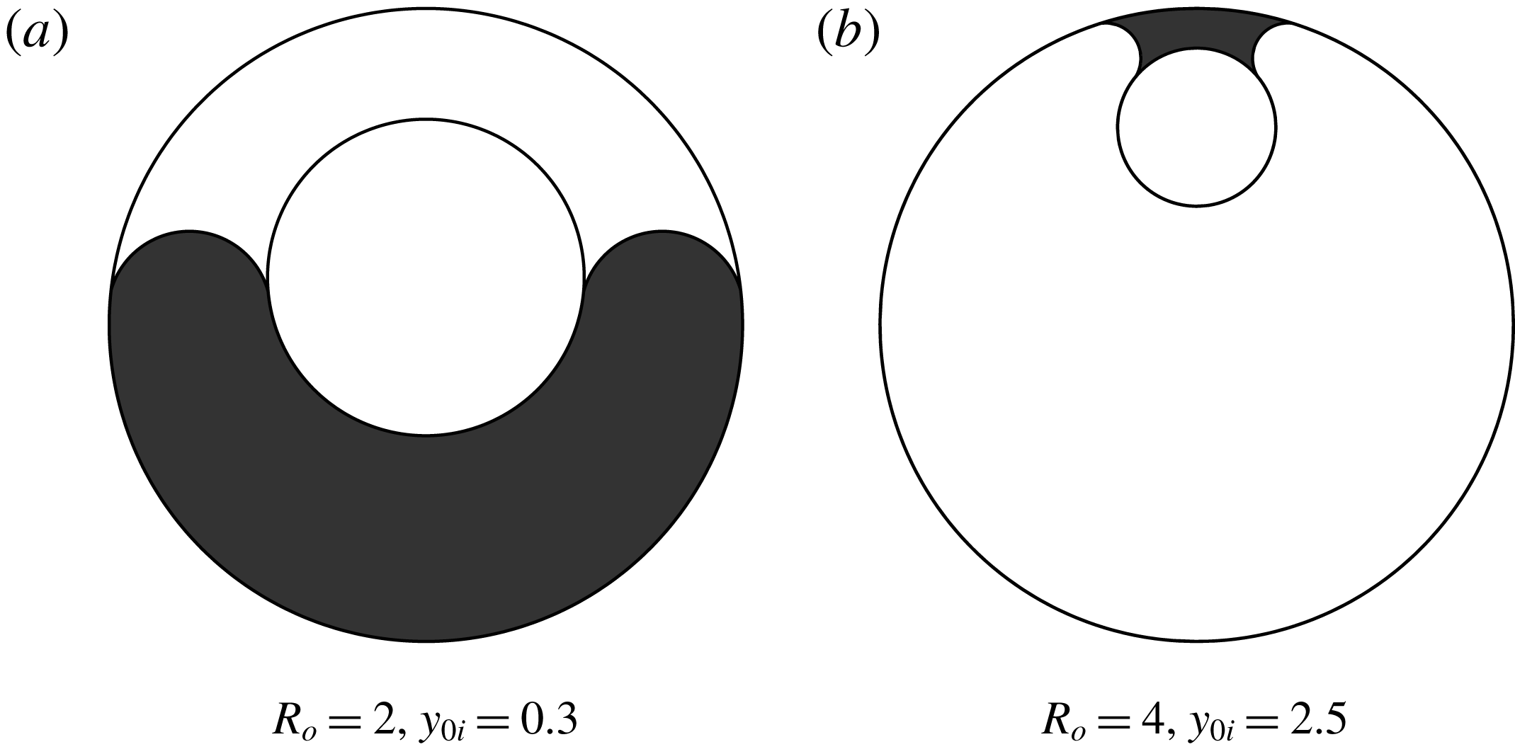
Figure 11. (a) Example case representing the largest fractional open area (25 %) for
 $\unicode[STIX]{x1D6FE}=170^{\circ }$
, and (b) a case with open area greater than 90 % for
$\unicode[STIX]{x1D6FE}=170^{\circ }$
, and (b) a case with open area greater than 90 % for
 $\unicode[STIX]{x1D6FE}=10^{\circ }$
.
$\unicode[STIX]{x1D6FE}=10^{\circ }$
.

Figure 12. Open area percentage versus contact angle for (a) the non-wetting cases with
 $R_{o}=2$
,
$R_{o}=2$
,
 $y_{0i}=0.3$
and (b) the wetting cases with
$y_{0i}=0.3$
and (b) the wetting cases with
 $R_{o}=4$
,
$R_{o}=4$
,
 $y_{0i}=2.5$
.
$y_{0i}=2.5$
.
4 Discussion and conclusions
We have examined the existence of long fluid segments in the eccentric annulus between two nested rigidly fixed cylinders with offset centres. A transition between occluding and non-occluding configurations of the fluid segment was found in accordance with prior work on this geometry for wetting cases by Smedley (Reference Smedley1990). We have further found a regime of parameter space for both wetting and non-wetting liquids where the bridging non-occluding shapes are apparently stable but have a higher free energy than the occluding shapes. The size of this bistable regime is strongly dependent on the wetting condition of the minority fluid on the walls of the conduit and is larger for highly wetting and non-wetting conditions than for cases closer to neutral wetting. The open area in the conduit for a non-occluding fluid segment is also found to be greater for either the more extreme wetting or non-wetting contact angles. These results may be important for applications involving the segregation and transport of two fluid phases in large-aspect-ratio channels.
For the non-occluding configurations, we solved the eigenvalue problem associated with the second variation of free energy (Bostwick & Steen Reference Bostwick and Steen2015) to determine the stability of the fluid configurations. The form of this problem for free surfaces of cylindrical section with a free contact line is given in appendix B, following the development of Roy & Schwartz (Reference Roy and Schwartz1999). The eigenvalues computed for a given equilibrium shape are associated with particular disturbances of the free surface. Negative eigenvalues represent unstable eigenmodes. The smallest eigenvalue was determined for non-occluding shapes in both the bistable region and non-occlusion region shown in figure 4 for all four contact angles and were all found to be positive, indicating that these configurations are stable. The stability of occluded shapes in the bistable region was explored using the Hessian matrix capabilities of Surface Evolver (Brakke Reference Brakke1996). Code for evolving our surfaces using angular guide plane constraints in place of convex constraints on the curved boundaries was provided by (K. A. Brakke, 2018, Personal communication), which allowed the use of the Hessian analysis within Surface Evolver. After a surface is evolved to equilibrium, the eigenvalues of the Hessian are found. Stability is indicated if all eigenvalues are positive. Because of the long computational time required for evolving the surface with Surface Evolver, only a few cases were tested within the bistable and occluding regions and these were found to be stable.
Although the occluding configuration is energetically preferred in the bistable region, it is argued that hysteresis will play a role in determining which configuration exists at a particular time. For example, in an application where small droplets coalesce to form a large wall-bound drop in the conduit, the growing drop would initially form a bridging (non-occluding) configuration and remain in that state unless a large enough disturbance causes it to transition to the occluding state. Hysteresis would also be expected for continuous changes in geometry, such as moving the centre rod. If we start with an occluding configuration above the bistable region and increase the centre rod offset,
 $y_{0i}$
, we expect the channel to remain occluded through the bistable window until the lower boundary of the bistable region is reached, at which point transition to non-occlusion is expected. This transition is analogous to that seen for a related vane gap geometry both in drop tower experiments (Chen & Collicott Reference Chen and Collicott2006) and in the CFE-2 VG-1/VG-2 experiments on the International Space Station (Blackmore et al.
Reference Blackmore, Weislogel, Chen, Kiewidt, Klatte and Bunnell2011). Conversely, if the liquid starts in the non-occluded configuration below the bistable region and the centre rod offset is decreased, we expect the non-occluding configuration to persist through the bistable region until the upper boundary of the bistable region is reached and a transition to occlusion would occur. Note that, in this work, we always assume that contact angles are at their equilibrium values, so the hysteresis is a configurational hysteresis not dependent on contact line hysteresis. Hysteresis of the type expected here has been seen recently in experiments on liquid columns bridging between parallel fibres (Protiere et al.
Reference Protiere, Duprat and Stone2013) when the fibre spacing is changed continuously. Although, in this work, we have studied the equilibrium configurations for prescribed values of static contact angles, one can model the effect of hysteresis by a study of the variation of the equilibria with contact angle (Michael Reference Michael1981).
$y_{0i}$
, we expect the channel to remain occluded through the bistable window until the lower boundary of the bistable region is reached, at which point transition to non-occlusion is expected. This transition is analogous to that seen for a related vane gap geometry both in drop tower experiments (Chen & Collicott Reference Chen and Collicott2006) and in the CFE-2 VG-1/VG-2 experiments on the International Space Station (Blackmore et al.
Reference Blackmore, Weislogel, Chen, Kiewidt, Klatte and Bunnell2011). Conversely, if the liquid starts in the non-occluded configuration below the bistable region and the centre rod offset is decreased, we expect the non-occluding configuration to persist through the bistable region until the upper boundary of the bistable region is reached and a transition to occlusion would occur. Note that, in this work, we always assume that contact angles are at their equilibrium values, so the hysteresis is a configurational hysteresis not dependent on contact line hysteresis. Hysteresis of the type expected here has been seen recently in experiments on liquid columns bridging between parallel fibres (Protiere et al.
Reference Protiere, Duprat and Stone2013) when the fibre spacing is changed continuously. Although, in this work, we have studied the equilibrium configurations for prescribed values of static contact angles, one can model the effect of hysteresis by a study of the variation of the equilibria with contact angle (Michael Reference Michael1981).
Acknowledgement
The authors would like to express their appreciation to Professor K. A. Brakke for his very kind guidance through the Surface Evolver modelling. N.B.P. would like to acknowledge support from NSF projects 1432674 and 1821578.
Appendix A. Cross-sectional liquid area and wetted boundary for the wetting fluid segment
For a wetting liquid, the fluid moves to the narrow part of the annulus; thus the limits of integration for finding the wetted surface arclengths and cross-sectional area of liquid are changed. The arclengths of the wetted boundary for the wetting case are then
 $$\begin{eqnarray}|\unicode[STIX]{x1D6F4}_{i}^{\ast }|=2(\unicode[STIX]{x03C0}/2-\unicode[STIX]{x1D719}_{c}),\quad |\unicode[STIX]{x1D6F4}_{o}^{\ast }|=2R_{o}(\unicode[STIX]{x03C0}/2-\unicode[STIX]{x1D703}_{c}),\end{eqnarray}$$
and the cross-sectional area of liquid is
 $$\begin{eqnarray}|\unicode[STIX]{x1D6FA}^{\ast }|=\int _{\unicode[STIX]{x1D703}_{c}}^{\unicode[STIX]{x03C0}/2}\hat{\boldsymbol{k}}\boldsymbol{\cdot }\left(\boldsymbol{r}_{\unicode[STIX]{x1D6F4}_{o}}\times \frac{\text{d}\boldsymbol{r}_{\unicode[STIX]{x1D6F4}_{o}}}{\text{d}\unicode[STIX]{x1D703}}\right)\text{d}\unicode[STIX]{x1D703}+\int _{\unicode[STIX]{x1D702}_{ci}}^{\unicode[STIX]{x1D702}_{co}}\hat{\boldsymbol{k}}\boldsymbol{\cdot }\left(\boldsymbol{r}_{\unicode[STIX]{x1D6E4}}\times \frac{\text{d}\boldsymbol{r}_{\unicode[STIX]{x1D6E4}}}{\text{d}\unicode[STIX]{x1D702}}\right)\text{d}\unicode[STIX]{x1D702}+\int _{\unicode[STIX]{x03C0}/2}^{\unicode[STIX]{x1D719}_{c}}\hat{\boldsymbol{k}}\boldsymbol{\cdot }\left(\boldsymbol{r}_{\unicode[STIX]{x1D6F4}_{i}}\times \frac{\text{d}\boldsymbol{r}_{\unicode[STIX]{x1D6F4}_{i}}}{\text{d}\unicode[STIX]{x1D719}}\right)\text{d}\unicode[STIX]{x1D719}.\end{eqnarray}$$
This becomes
 $$\begin{eqnarray}\displaystyle |\unicode[STIX]{x1D6FA}^{\ast }| & = & \displaystyle R_{o}^{2}(\unicode[STIX]{x03C0}/2-\unicode[STIX]{x1D703}_{c})-|R_{m}|^{2}(\unicode[STIX]{x1D702}_{ci}-\unicode[STIX]{x1D702}_{co})-|R_{m}|x_{0m}(\sin \unicode[STIX]{x1D702}_{ci}-\sin \unicode[STIX]{x1D702}_{co})\nonumber\\ \displaystyle & & \displaystyle +\,|R_{m}|y_{0m}(\cos \unicode[STIX]{x1D702}_{ci}-\cos \unicode[STIX]{x1D702}_{co})-(\unicode[STIX]{x03C0}/2-\unicode[STIX]{x1D719}_{c})-y_{0i}\cos \unicode[STIX]{x1D719}_{c}.\end{eqnarray}$$
The limits on the free-surface parameter
 $\unicode[STIX]{x1D702}$
are given by
$\unicode[STIX]{x1D702}$
are given by
 $$\begin{eqnarray}\displaystyle \left.\begin{array}{@{}c@{}}\left.\begin{array}{@{}l@{}}\unicode[STIX]{x1D702}_{co}=\unicode[STIX]{x1D703}_{c}+\unicode[STIX]{x1D6FE}\\ \unicode[STIX]{x1D702}_{ci}=\unicode[STIX]{x1D719}_{c}-\unicode[STIX]{x1D6FE}+\unicode[STIX]{x03C0}\end{array}\right\}\quad R_{m}<0,\\ \left.\begin{array}{@{}l@{}}\unicode[STIX]{x1D702}_{co}=\unicode[STIX]{x1D703}_{c}+\unicode[STIX]{x1D6FE}-\unicode[STIX]{x03C0}\\ \unicode[STIX]{x1D702}_{ci}=\unicode[STIX]{x1D719}_{c}-\unicode[STIX]{x1D6FE}\end{array}\right\}\quad R_{m}>0,\end{array}\right\} & & \displaystyle\end{eqnarray}$$
where the sign of
 $R_{m}$
is found from
$R_{m}$
is found from
 $$\begin{eqnarray}\operatorname{sgn}(R_{m})=\operatorname{sgn}[\sin (\unicode[STIX]{x1D703}_{c}-\unicode[STIX]{x1D719}_{c}+2\unicode[STIX]{x1D6FE})].\end{eqnarray}$$
Appendix B. The stability of non-occluding shapes
The stability of capillary equilibria can be judged from the sign of the lowest eigenvalue of an eigenvalue problem associated with the second variation of free energy, where negative eigenvalues indicate instability of the associated eigenmodes (Brinkmann, Kierfeld & Lipowsky Reference Brinkmann, Kierfeld and Lipowsky2004; Bostwick & Steen Reference Bostwick and Steen2015). The form of this eigenvalue problem for general surface shapes can be found, for example, in Brinkmann et al. (Reference Brinkmann, Kierfeld and Lipowsky2004) and in Bostwick & Steen (Reference Bostwick and Steen2015). The problem is simplified for the case of a surface of cylindrical section. The development presented here follows that of Roy & Schwartz (Reference Roy and Schwartz1999), who examined the stability of liquid ridges of circular-arc shape on various substrates. The eigenvalue problem is
 $$\begin{eqnarray}\unicode[STIX]{x1D702}_{ss}+\unicode[STIX]{x1D702}_{zz}+\unicode[STIX]{x1D705}^{2}\unicode[STIX]{x1D702}+\unicode[STIX]{x1D707}_{0}+\unicode[STIX]{x1D707}\unicode[STIX]{x1D702}=0,\end{eqnarray}$$
where
 $\unicode[STIX]{x1D702}$
represents a normal disturbance to the equilibrium shape, which is a function of
$\unicode[STIX]{x1D702}$
represents a normal disturbance to the equilibrium shape, which is a function of
 $s$
, the arclength along the free surface in the transverse direction, and
$s$
, the arclength along the free surface in the transverse direction, and
 $z$
, the axial distance down the conduit. For the case of a pressure constraint rather than a volume constraint on the system, we have
$z$
, the axial distance down the conduit. For the case of a pressure constraint rather than a volume constraint on the system, we have
 $\unicode[STIX]{x1D707}_{0}=0$
(Brown & Scriven Reference Brown and Scriven1980). The pressure constraint is used in systems with disconnected but identical free surfaces where the fluid is connected through the volume (Slobozhanin & Alexander Reference Slobozhanin and Alexander2003), which applies in our case. Disturbances are subject to constant contact angle conditions on the inner (
$\unicode[STIX]{x1D707}_{0}=0$
(Brown & Scriven Reference Brown and Scriven1980). The pressure constraint is used in systems with disconnected but identical free surfaces where the fluid is connected through the volume (Slobozhanin & Alexander Reference Slobozhanin and Alexander2003), which applies in our case. Disturbances are subject to constant contact angle conditions on the inner (
 $s=s_{0}$
) and outer (
$s=s_{0}$
) and outer (
 $s=s_{1}$
) cylinder walls given by
$s=s_{1}$
) cylinder walls given by
 $$\begin{eqnarray}-\unicode[STIX]{x1D702}_{s}(s_{0},z)+\unicode[STIX]{x1D6FC}_{0}\unicode[STIX]{x1D702}(s_{0},z)=0,\quad \unicode[STIX]{x1D702}_{s}(s_{1},z)+\unicode[STIX]{x1D6FC}_{1}\unicode[STIX]{x1D702}(s_{1},z)=0,\end{eqnarray}$$
where
 $\unicode[STIX]{x1D6FC}$
is
$\unicode[STIX]{x1D6FC}$
is
 $$\begin{eqnarray}\unicode[STIX]{x1D6FC}_{i}=\left[\frac{S_{\unicode[STIX]{x1D705}}\unicode[STIX]{x1D705}\cos \unicode[STIX]{x1D6FE}+S_{\unicode[STIX]{x1D705}_{w}}\unicode[STIX]{x1D705}_{w}}{\sin \unicode[STIX]{x1D6FE}}\right]_{i}\quad \text{for}~i=0,1,\end{eqnarray}$$
and where
 $\unicode[STIX]{x1D705}$
and
$\unicode[STIX]{x1D705}$
and
 $\unicode[STIX]{x1D705}_{w}$
are the absolute values of the normal curvature of the meniscus and wall evaluated at the respective contact line (
$\unicode[STIX]{x1D705}_{w}$
are the absolute values of the normal curvature of the meniscus and wall evaluated at the respective contact line (
 $s_{0}$
or
$s_{0}$
or
 $s_{1}$
). The signs associated with the meniscus and wall curvatures are taken as follows:
$s_{1}$
). The signs associated with the meniscus and wall curvatures are taken as follows:
 $$\begin{eqnarray}S_{\unicode[STIX]{x1D705}}=\operatorname{sgn}(\unicode[STIX]{x1D73F}\boldsymbol{\cdot }\hat{\boldsymbol{n}}_{s}),\quad S_{\unicode[STIX]{x1D705}_{w}}=\operatorname{sgn}(\unicode[STIX]{x1D73F}_{w}\boldsymbol{\cdot }\hat{\boldsymbol{n}}_{w}),\end{eqnarray}$$
where
 $\unicode[STIX]{x1D73F}$
and
$\unicode[STIX]{x1D73F}$
and
 $\unicode[STIX]{x1D73F}_{w}$
are the curvature vectors of the meniscus and wall, respectively, and
$\unicode[STIX]{x1D73F}_{w}$
are the curvature vectors of the meniscus and wall, respectively, and
 $\hat{\boldsymbol{n}}_{s}$
and
$\hat{\boldsymbol{n}}_{s}$
and
 $\hat{\boldsymbol{n}}_{w}$
are unit exterior normals to the fluid volume for the free surface and wall, respectively. Note that the curvatures are those within the plane of constant
$\hat{\boldsymbol{n}}_{w}$
are unit exterior normals to the fluid volume for the free surface and wall, respectively. Note that the curvatures are those within the plane of constant
 $z$
. The liquid segment of length
$z$
. The liquid segment of length
 $L$
is taken to be bound on the ends by planar walls with
$L$
is taken to be bound on the ends by planar walls with
 $90^{\circ }$
contact angles, giving the axial boundary conditions
$90^{\circ }$
contact angles, giving the axial boundary conditions
 $$\begin{eqnarray}\unicode[STIX]{x1D702}_{z}(s,0)=\unicode[STIX]{x1D702}_{z}(s,L)=0.\end{eqnarray}$$
The stability of the meniscus is determined from the sign of the smallest eigenvalue
 $\unicode[STIX]{x1D707}$
of this eigenvalue problem. The separation-of-variables solution that satisfies the boundary conditions at the ends is
$\unicode[STIX]{x1D707}$
of this eigenvalue problem. The separation-of-variables solution that satisfies the boundary conditions at the ends is
 $$\begin{eqnarray}\unicode[STIX]{x1D702}(s,z)=[A\cos (\unicode[STIX]{x1D709}s)+B\sin (\unicode[STIX]{x1D709}s)]\cos \left(\frac{n\unicode[STIX]{x03C0}z}{L}\right).\end{eqnarray}$$
This satisfies the differential equation provided that the eigenvalue is
 $$\begin{eqnarray}\unicode[STIX]{x1D707}=\unicode[STIX]{x1D709}^{2}-\unicode[STIX]{x1D705}^{2}+\left(\frac{n\unicode[STIX]{x03C0}}{L}\right)^{2}.\end{eqnarray}$$
Applying the boundary conditions at the lateral contact lines and taking
 $s_{0}=0$
leads to the requirement that the transverse wavenumber,
$s_{0}=0$
leads to the requirement that the transverse wavenumber,
 $\unicode[STIX]{x1D709}$
, satisfies the following condition:
$\unicode[STIX]{x1D709}$
, satisfies the following condition:
 $$\begin{eqnarray}\unicode[STIX]{x1D709}(\unicode[STIX]{x1D6FC}_{1}-\unicode[STIX]{x1D6FC}_{0})\cos (\unicode[STIX]{x1D709}s_{1})-(\unicode[STIX]{x1D709}^{2}+\unicode[STIX]{x1D6FC}_{0}\unicode[STIX]{x1D6FC}_{1})\sin (\unicode[STIX]{x1D709}s_{1})=0.\end{eqnarray}$$
Because instability is indicated by the presence of a single negative eigenvalue, we are only interested in the smallest non-zero root of this equation,
 $\unicode[STIX]{x1D709}_{0}$
. The smallest eigenvalue will then be
$\unicode[STIX]{x1D709}_{0}$
. The smallest eigenvalue will then be
 $$\begin{eqnarray}\unicode[STIX]{x1D707}_{0}=\unicode[STIX]{x1D709}_{0}^{2}-\unicode[STIX]{x1D705}^{2}.\end{eqnarray}$$
The smallest eigenvalue was found to be positive for the non-occluding shapes over their range of existence within the parameter range studied in this work (the light and dark shaded regions in figure 4).
Appendix C. Asymmetric non-occluding configurations at the pressure turning point
The loss of stability of the symmetric solution at a pressure turning point found for the case of a
 $70^{\circ }$
contact angle may lead to channel occlusion or could lead to a new asymmetric non-occluding configuration. Asymmetric solutions in which the meniscus advances a different distance on the two halves of the channel would be mechanically allowed because of the pressure turning point. That is, there are two positions of the meniscus that give the same pressure, one on either side of the turning point. Whether such configurations would be stable can be judged by whether a free-energy minimum is found. Here we develop the free-energy expression for asymmetric configurations. The function
$70^{\circ }$
contact angle may lead to channel occlusion or could lead to a new asymmetric non-occluding configuration. Asymmetric solutions in which the meniscus advances a different distance on the two halves of the channel would be mechanically allowed because of the pressure turning point. That is, there are two positions of the meniscus that give the same pressure, one on either side of the turning point. Whether such configurations would be stable can be judged by whether a free-energy minimum is found. Here we develop the free-energy expression for asymmetric configurations. The function
 $\unicode[STIX]{x1D6F7}$
will now be computed for different shapes on the two halves, left (
$\unicode[STIX]{x1D6F7}$
will now be computed for different shapes on the two halves, left (
 $L$
) and right (
$L$
) and right (
 $R$
). The free energy relative to the occluded configuration for the asymmetric segment would be
$R$
). The free energy relative to the occluded configuration for the asymmetric segment would be
 $$\begin{eqnarray}F-F_{1}=\unicode[STIX]{x1D6F7}_{L}(|\unicode[STIX]{x1D6FA}_{L}^{\ast }|)\frac{V_{L}}{|\unicode[STIX]{x1D6FA}_{L}^{\ast }|}\unicode[STIX]{x1D70E}_{LV}+\unicode[STIX]{x1D6F7}_{R}(|\unicode[STIX]{x1D6FA}_{R}^{\ast }|)\frac{V_{R}}{|\unicode[STIX]{x1D6FA}_{R}^{\ast }|}\unicode[STIX]{x1D70E}_{LV}.\end{eqnarray}$$
The volume of each half can be written in terms of the total segment volume as
 $$\begin{eqnarray}\frac{V_{L}}{V}=\frac{|\unicode[STIX]{x1D6FA}_{L}^{\ast }|}{|\unicode[STIX]{x1D6FA}_{L}^{\ast }|+|\unicode[STIX]{x1D6FA}_{R}^{\ast }|},\quad \frac{V_{R}}{V}=\frac{|\unicode[STIX]{x1D6FA}_{R}^{\ast }|}{|\unicode[STIX]{x1D6FA}_{L}^{\ast }|+|\unicode[STIX]{x1D6FA}_{R}^{\ast }|}.\end{eqnarray}$$
The free-energy function can be rewritten as a volume-weighted average of the free energy per volume for the two sides:
 $$\begin{eqnarray}F-F_{1}=\left[\frac{|\unicode[STIX]{x1D6FA}_{L}^{\ast }|\hat{F}_{L}+|\unicode[STIX]{x1D6FA}_{R}^{\ast }|\hat{F}_{R}}{|\unicode[STIX]{x1D6FA}_{L}^{\ast }|+|\unicode[STIX]{x1D6FA}_{R}^{\ast }|}\right]V\unicode[STIX]{x1D70E}_{LV},\end{eqnarray}$$
where
 $$\begin{eqnarray}\hat{F}_{L}=\unicode[STIX]{x1D70E}_{LV}\frac{\unicode[STIX]{x1D6F7}(|\unicode[STIX]{x1D6FA}_{L}^{\ast }|)}{|\unicode[STIX]{x1D6FA}_{L}^{\ast }|},\quad \hat{F}_{R}=\unicode[STIX]{x1D70E}_{LV}\frac{\unicode[STIX]{x1D6F7}(|\unicode[STIX]{x1D6FA}_{R}^{\ast }|)}{|\unicode[STIX]{x1D6FA}_{R}^{\ast }|}.\end{eqnarray}$$
The area and free-energy contributions from a set of shapes with equal pressures but increasingly different contact line positions on opposite sides of the pressure turning point are computed to assess how free energy changes with asymmetry.


