NOMENCLATURE
- AL
-
alarm limits
- APV-1
-
approach with vertical guidance
- ASAS
-
African Satellite Augmentation System
- ASG-EUPOS
-
Aktywna Sieć Geodezyjna EUPOS
- c
-
speed of light
- C/A
-
course/acquisition
- CODE
-
Center for Orbit Determination in Europe
- DGPS
-
differential global positioning system
- EGNOS
-
European Geostationary Navigation Overlay Service
- EUPOS
-
European Position Determination System
- GAGAN
-
GPS aided GEO augmented and navigation system
- GBAS
-
ground-based augmentation system
- GNSS
-
global navigation satellite systems
- GPS
-
global positioning system
- HPE
-
horizontal position error
- HPL
-
horizontal protection level
- ICAO
-
International Civil Aviation Organization
- IGS
-
International GNSS Service
- ITRF2000
-
International Terrestrial Reference Frame 2000
- ITRS
-
International Terrestrial Reference System
- MI
-
misleading information
- MOPS
-
minimum operational performance standards
- MSAS
-
MTSAT satellite augmentation system
- NPA
-
non-precision approach
- OS
-
open service
- PA
-
precision approach
- PRN
-
pseudorandom noise
- RIMS
-
ranging and integrity monitoring stations
- RNAV
-
area navigation
- S
-
projection matrix
- SBAS
-
satellite-based augmentation systems
- SDCM
-
Russian wide area augmentation system
- SI
-
safety index
- SLM
-
single layer model
- SoL
-
safety of life service
- SPS
-
standard positioning service
- TEC
-
total electron content
- VPE
-
vertical position error
- VPL
-
vertical protection level
- WAAS
-
wide area augmentation system
- WRS
-
RIMS station located in Warsaw
- d 2 E , dN 2, d 2 U
-
variances of the east, north and up (vertical) components of the position solution expressed in a topocentric system
- d 2 EN
-
covariance between the east and north axes
- FPP
-
obliquity factor (transforms vertical delay to slant)
- KH
-
a factor bounding user's horizontal position with a probability of 10−9 (for en route navigation KH = 6.18 and for precision approach KH = 6.0)
- K V
-
a factor bounding the user's vertical position with a probability of 0.5 × 10⁻⁷ (K V = 5.33)
- S E, i
-
the partial derivative of position error in the east direction with respect to the pseudorange error on the ith satellite
- S N, i
-
the partial derivative of position error in the north direction with respect to the pseudorange error on the ith satellite
- S U, i
-
the partial derivative of position error in the up (vertical) direction with respect to the pseudorange error on the ith satellite
- Wn
-
weighting function
- Tiono
-
ionospheric corrections of Klobuchar error model
- xSI
-
horizontal or vertical safety index
- xPE
-
horizontal or vertical position error
- xPL
-
horizontal or vertical protection level
- xPP , yPP
-
coordinates of interpolation grid points
- σ2 i
-
full variance of the pseudorange measurement
- σ2 i, flt
-
variance of the residual error after the application of fast and slow corrections
- σ2 i, UIRE
-
variance of the residual error after the application of ionospheric correction
- σ2 i, air
-
variance of the contribution of the receiver to the residual error
- σ2 i, tropo
-
variance of the residual error after the application of tropospheric correction
- σ2 n, ionogrid
-
grid ionospheric vertical error bound with degradation over time
- σ2 GIVE
-
grid ionospheric vertical error bound
- ε2 iono
-
degradation of ionospheric correction information
- Φ m
-
geomagnetic latitude (in degrees) of ionospheric pierce point
1.0 INTRODUCTION
The aim of Satellite-Based Augmentation Systems (SBASs) systems is to support Global Navigation Satellite Systems (GNSSs) positioning in their area of operation(1). Through the work of ground stations and geostationary satellites, SBAS systems transmit data to improve the quality of positioning and information on the integrity of GNSS systems(2). Operational SBAS systems include the American Wide Area Augmentation System (WAAS), the European Geostationary Navigation Overlay Service (EGNOS), Japanese MTSAT Satellite Augmentation System (MSAS) and the GPS-Aided GEO Augmented and Navigation System (GAGAN). Russia is finalising the work on their Russian Wide Area Augmentation System (SDCM). Work is also underway on the new GNSS supporting systems—for example, the African Satellite Augmentation System (ASAS) under development in Africa(Reference Ilcev3).
EGNOS supports the SPS of GPS and operates in Europe(2). This is done by using the L1 frequency and the C/A code. Providing correction data and integrity information, EGNOS improves satellite positioning, navigation and timing services. Performance of the system has changed significantly over the last few years. Open Service (OS), which improves GPS performances for the users of general-purpose applications has been operational since 2009, while Safety of Life Service–SoL (based on data integrity transmitted by geostationary satellites) has been available since 2011. Gradual improvements of the EGNOS system caused a significant expansion of its area of operation and improvement of positioning results.
EGNOS can be used in air transport in the case of approaches and landing types based on Area Nagviation (RNAV)(4). Non-Precision Approach (NPA) uses EGNOS only for lateral guidance. APV-1 is an instrument procedure, which does not meet the precision approach requirements, but uses lateral and vertical guidance. To implement EGNOS in aviation, it is necessary to fulfil a number of requirements and adjust to existing international guidelines developed by the International Civil Aviation Organisation (ICAO)(2).
Monitoring the EGNOS performance should be done locally, because in different places you may expect different results of positioning(Reference Felski and Nowak5,Reference Vassilev and Vassileva6) . The research on the quality of the EGNOS in Poland carried out in recent years has shown that a lack of a RIMS station east of Warsaw impairs the quality of the system (especially in eastern Poland, where Differential Global Positioning System (DGPS) was usually used instead)(Reference Felski, Nowak and Woźniak7-Reference Popielarczyk and Templin10). However, in 2014, a new document was published by the European Commission's Directorate-General for Enterprise and Industry that the declared area of EGNOS OS coverage was greatly expanded east of the WRS station located in Warsaw. Figure 1 shows the EGNOS OS compliance area presented by the European Commission's Directorate-General for Enterprise and Industry in 2009 and in 2014.

In addition, in November 2013 an agreement was signed between the European Commission and Ukraine to include the territory of Ukraine in the range of the EGNOS(Reference Konin and Shyshkov12). The creation of a RIMS station in Ukraine would definitely also improve the performance of the EGNOS in Poland (especially the eastern regions). However, prior research carried out in 2012 in this country already shows a significant improvement in EGNOS performance (APV-1 approach requirements were met) but does not guarantee the full coverage of the system throughout the country. Thus, studies on EGNOS quality seem to be reasonable in an area that, according to the declaration of the European Commission's Directorate-General for Enterprise and Industry (2014), has been greatly expanded despite the lack of RIMS station in Ukraine.
Since the ionosphere is the main source of errors in GNSS positioning, research on this parameter and its role in Global Positioning System (GPS)/EGNOS positioning in Poland is very important(Reference Świątek, Stanisławska, Zbyszyński and Dziak-Jankowska13). In case of basic single-frequency GPS receivers the ionospheric delay is determined based on coefficients transmitted in the navigation message(Reference Klobuchar14). They are determined by virtue of Klobuchar model, which is characterised by a simple process of calculation and uncomplicated structure(Reference Klobuchar14,Reference Yuan, Huo, Ou, Zhang and Chai15) . It is defined as an SLM, since in the calculation of the theoretical delay, it uses the layer of the ionosphere at an altitude of 350 km above the Earth's surface. The Klobuchar model generates different delay values for daytime and nighttime. It eliminates the ionospheric delay by 50-60% on the base of the TEC (total electron content) coefficient between the satellite and the receiver. Its effectiveness is dependent on solar activity and user location.
In contrast, SBAS systems use a thin-shell approximation of the ionosphere and send the delay values determined for the grid points(Reference Arbesser-Rastburg16). Based on that, the algorithm computes the delay for ionospheric pierce point (at an altitude of 350 km). For middle latitudes, grid points are spaced every 5° latitude and 5° longitude, and for the high latitudes the spacing is 30°(Reference Jakowski, Borries and Wilken17).
Receivers using the Galileo system for positioning use the NeQuick ionosphere model, which was originally used in the analysis of the EGNOS system(Reference Angrisano, Gaglione, Gioia, Massaro and Robustelli18,Reference Radicella19) .
Since 2000, the Center for Orbit Determination in Europe (CODE) has been providing Klobuchar-style coefficients(Reference Mageed20). They are formed on the basis of the International GNSS Service (IGS) GPS observation data(21). Using the post-fit coefficients gives much better positioning results than the original Klobuchar coefficients transmitted in the navigation message(Reference Øvstedal22). However, they are determined with several days' delay, so they can be only used in post-processing studies. Nevertheless, the CODE also provides predicted coefficients, which, according to the authors, should give better positioning results than the traditional Klobuchar model(21). The results of studies conducted so far related to the Klobuchar-style coefficients provided by CODE showed better positioning accuracy than that provided through the original Klobuchar model(Reference Yuan, Huo, Ou, Zhang and Chai15).
2.0 ACCURACY AND INTEGRITY OF GPS/EGNOS POSITIONING IN AIR NAVIGATION
According to the US government's Federal Radionavigation Plan(23), the accuracy of an estimated or measured position at a given time is the degree of conformance of that location with the true position of the receiver at that time (it should be given with uncertainty in position that applies).
The results of positioning using EGNOS are expressed in the EGNOS Terrestrial Reference Frame, which is the realisation of the ITRS (2). The difference between the EGNOS Terrestrial Reference Frame and the ITRF2000 reaches a value of a few centimetres (such as between systems EGNOS Terrestrial Reference Frame and WGS84). Thus, for navigation analyses, it can be assumed that the results of the GPS/EGNOS positioning are expressed in the ITRF2000 frame.
GPS/EGNOS positioning accuracy in Polish territory can be examined on the basis of true coordinates of the receiver determined by a network of reference stations of ASG-EUPOS system (the Polish part of the European Position Determination System (EUPOS)). The coordinates of the ASG-EUPOS reference stations are expressed in the Polish PL-ETRF2000 frame (reference epoch 2011.0 of the European Terrestrial Reference Frame 2000)(24,2) . Thus, the reference coordinates expressed in the PL-ERTF2000 system can be easily transformed into the ITRF2000. The Horizontal Position Error (HPE) and Vertical Position Error (VPE) for each epoch can be calculated by comparing the determined position with the reference.
Integrity can be defined as a probability measure, which guarantees to contain the calculated horizontal position provided by the navigation system(23).
To express the level of integrity in real time, protection levels in the horizontal and vertical planes are used(Reference Azaola-Saenz and Cosmen-Shortmann25).
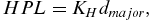
Horizontal Protection Level (HPL) is defined by the radius of the circle in the horizontal plane (with the centre on the real position), which describes the zone that is guaranteed to contain the horizontal position calculated. Vertical Protection Level (VPL) is the length of half of the cylinder's axis (with the centre on the real position) corresponding to the zone guaranteed to contain the vertical position calculated(1). It is recognised that integrity is met when the protection level values do not exceed the defined alarm limit thresholds for a given phase of flight(Reference Azaola-Saenz and Cosmen-Shortmann25,26) .
The values of protection levels are calculated on the basis of these formulae(1,Reference Oliveira and Tiberius27) :
 $$\begin{equation}
HPL = {K_H}{d_{major}},
\end{equation}$$
$$\begin{equation}
HPL = {K_H}{d_{major}},
\end{equation}$$
 $$\begin{equation}
VPL = {K_V}{d_U},
\end{equation}$$
$$\begin{equation}
VPL = {K_V}{d_U},
\end{equation}$$
where:
-
KH is a factor bounding user's horizontal position with a probability of 10−9 (for en-route navigation KH = 6.18 and for precision approach KH = 6.0),
-
K V is a factor bounding the user's vertical position with a probability of 0.5 × 10⁻⁷ (KV = 5.33).
(3) $$\begin{equation}{d_{major}} = \sqrt {\frac{{d_E^2 + d_N^2}}{2} + \sqrt {{{\left( {\frac{{d_E^2 - d_N^2}}{2}} \right)}^2} + d_{EN}^2{\rm{\ }}} } ,\end{equation}$$
(4)
$$\begin{equation}d_E^2 = \mathop \sum \limits_{i = 1}^n S_{E,\,i}^2\sigma _i^2,\;\ d_N^2 = \mathop \sum \limits_{i = 1}^n S_{N,i}^2\sigma _i^2,\;{d_{EN}} = \mathop \sum \limits_{i = 1}^n {S_{E,i}}{S_{N,i}}\sigma _i^2,\;d_U^2 = \mathop \sum \limits_{i = 1}^n {S_{U,i}}\sigma _i^2,\end{equation}$$
$$\begin{equation}{d_{major}} = \sqrt {\frac{{d_E^2 + d_N^2}}{2} + \sqrt {{{\left( {\frac{{d_E^2 - d_N^2}}{2}} \right)}^2} + d_{EN}^2{\rm{\ }}} } ,\end{equation}$$
(4)
$$\begin{equation}d_E^2 = \mathop \sum \limits_{i = 1}^n S_{E,\,i}^2\sigma _i^2,\;\ d_N^2 = \mathop \sum \limits_{i = 1}^n S_{N,i}^2\sigma _i^2,\;{d_{EN}} = \mathop \sum \limits_{i = 1}^n {S_{E,i}}{S_{N,i}}\sigma _i^2,\;d_U^2 = \mathop \sum \limits_{i = 1}^n {S_{U,i}}\sigma _i^2,\end{equation}$$


where:
-
S is the projection matrix,
-
d 2 E , dN 2 and d 2 U are variances of the east, north and up (vertical) components of the position solution expressed in a topocentric system,
-
d 2 EN is the covariance between the east and north axes,
-
S E, i is the partial derivative of position error in the east direction with respect to the pseudorange error on the ith satellite,
-
S N, i is the partial derivative of position error in the north direction with respect to the pseudorange error on the ith satellite,
-
S U, i is the partial derivative of position error in the up (vertical) direction with respect to the pseudorange error on the ith satellite.
(5)
$$\begin{equation}\sigma _i^2 = \ \sigma _{i,flt}^2 + \sigma _{i,\ UIRE}^2 + \sigma _{i,air}^2 + \ \sigma _{i,\ tropo}^2\end{equation}$$
-
σ2 i is the full variance of the pseudorange measurement,
-
σ2 i, flt is the variance of the residual error after the application of fast and slow corrections,
-
σ2 i, UIRE is the variance of the residual error after the application of ionospheric correction,
-
σ2 i, air is the variance of the contribution of the receiver to the residual error,
-
σ2 i, tropo is the variance of the residual error after the application of tropospheric correction.
(6)
$$\begin{equation}\sigma _{i,\ UIRE}^2 = F_{PP}^2\sigma _{i,\ UIVE}^2,\end{equation}$$
(7)
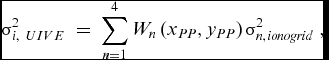
$$\begin{equation}\sigma _{i,\ UIVE\ }^2 = \ \mathop \sum \limits_{n = 1}^4 {W_n}\left( {{x_{PP}},{y_{PP}}} \right)\sigma _{n,ionogrid\ }^2,\end{equation}$$
(8)
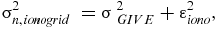
$$\begin{equation}\sigma _{n,ionogrid\ }^2 = \sigma \ _{GIVE}^2 + \varepsilon _{iono}^2,\end{equation}$$


where:
-
FPP is the obliquity factor (transforms vertical delay to slant),
-
Wn is the weighting function,
-
σ2 n, ionogrid is the grid ionospheric vertical error bound with degradation over time,
-
xPP , yPP are the coordinates of interpolation grid points,
-
σ2 UIVE is the grid ionospheric vertical error bound, and
-
ε2 iono is the degradation of ionospheric correction information.
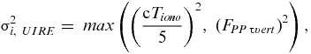
In case of the NPA (non-recision approach) and the phases of flight other than PA, instead of the original EGNOS model of ionosphere, the regular model (Klobuchar model) used in GPS SPS can be used. The error of the delay determination is then calculated based on the maximum value taken from the set of two elements described in this formula(1):
 $$\begin{equation}
\sigma _{i,\ UIRE}^2 = \ max\left( {{{\left( {\frac{{{\rm{c}}{T_{iono}}}}{5}} \right)}^2},\;{{({F_{PP\,}}_{\tau vert})}^2}} \right),
\end{equation}$$
$$\begin{equation}
\sigma _{i,\ UIRE}^2 = \ max\left( {{{\left( {\frac{{{\rm{c}}{T_{iono}}}}{5}} \right)}^2},\;{{({F_{PP\,}}_{\tau vert})}^2}} \right),
\end{equation}$$
where c is the speed of light and Tiono is the ionospheric corrections of the Klobuchar error model.
The τ vert is dependent on the geomagnetic latitude of ionospheric pierce point calculated on the basis of Klobuchar algorithm:
 $$\begin{equation}
{\tau _{vert}} = \ \left\{ {\begin{array}{*{20}{c}} {9\ m,\ \quad 0 \le \left| {{\Phi _m}} \right| \le 20}\\ {4.5\ m,\ \quad 20 < \left| {{\Phi _m}} \right| \le 55}\\ {6\ m,\quad \quad \quad \ 55 < \left| {{\Phi _m}} \right|} \end{array}} \!\!\right.,
\end{equation}$$
$$\begin{equation}
{\tau _{vert}} = \ \left\{ {\begin{array}{*{20}{c}} {9\ m,\ \quad 0 \le \left| {{\Phi _m}} \right| \le 20}\\ {4.5\ m,\ \quad 20 < \left| {{\Phi _m}} \right| \le 55}\\ {6\ m,\quad \quad \quad \ 55 < \left| {{\Phi _m}} \right|} \end{array}} \!\!\right.,
\end{equation}$$
where Φ m is the geomagnetic latitude (in degrees) of ionospheric pierce point.
When using Klobuchar-style (CODE) predicted coefficients for research purposes, the formulas in Bakul(Reference Bakuła9) and in Popielarczyk and Templin(Reference Popielarczyk and Templin10) can be used to determine the values of protection levels.
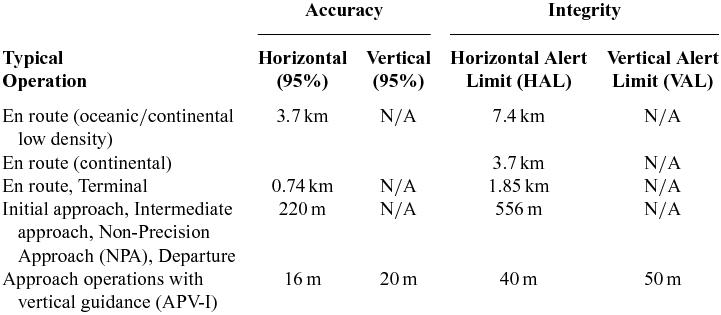
The test results of the accuracy and integrity of satellite positioning are used to verify the applicability of a particular navigation system in aviation. Based on the results of the long-term analyses, it can be determined if the system is ready for use in the flight procedure or in the approach and landing of an aircraft. Table 1 presents the requirements of the accuracy and integrity of satellite positioning systems used in air navigation.
Table 1 EGNOS accuracy and integrity requirements in aviation(26)

3.0 PRACTICAL STUDIES
In order to examine the accuracy and the parameters characterising the integrity of positioning, detailed analyses of GPS/EGNOS measurements were performed. Data were acquired at a permanent EGNOS monitoring station at the airport Olsztyn-Dajtki EPOD in northeastern Poland. The observations were recorded on 6-30 June 2014 with a Septentrio AsteRx2e receiver connected to a choke-ring antenna mounted on a specially adapted mast (Fig. 2). The selected location had been previously tested for the presence of potential interference of the GNSS signal with signals generated by the communications equipment installed at the airport.

Figure 2. GNSS antenna and computer set with GNSS receiver installed in the building of the Aeroclub of Warmia and Mazury.
The data were collected in 10-day sessions at 1-second intervals. Altogether, three full sessions were collected over 30 days. These were developed using the Septentrio Post Processing SDK application, a self-created PP-SBAS Analyser application and PEGASUS software, which is a set of tools that allows for the analysis of data collected from a variety of GNSS, SBAS and GBAS systems using algorithms defined in the MOPS documents.
Measurement data were processed in three variants of calculation:
-
- The original ionospheric GPS/EGNOS correction,
-
- Klobuchar ionospheric correction,
-
- CODE ionospheric model correction.
Each of the three variants is characterised by the same configuration parameters: elevation mask of 5°, exclusion from pseudorange positioning geostationary satellites, data recording intervals of one second, and EGNOS PRN125 satellite used (in case of unavailability of data from this satellite, data from PRN120 satellite were used). For the calculations only, the data which were not considered faulty during recording and processing (valid samples) were used. The ionosphere in the period from 1 June 2014 to 30 June 2014 was stable, except on 7, 8 and 18 June, during which the values of the Kp factor characterising the activity of the Earth's electromagnetic field exceeded the limit values (Kp = 4).
3.1 Accuracy analyses
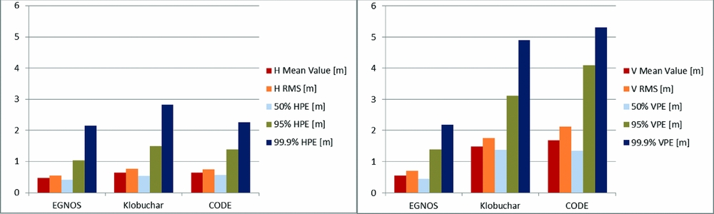
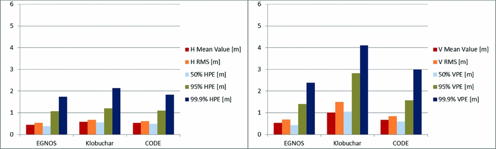
Figures 3-5 present horizontal (HPE) and vertical (VPE) position error analyses in the examined period based on the three variants of calculations. The detailed error analyses were performed including mean value of the absolute position error (H/V mean value), root mean square (RMS) and the errors characterised by confidence levels of 50%, 95% and 99.9%.
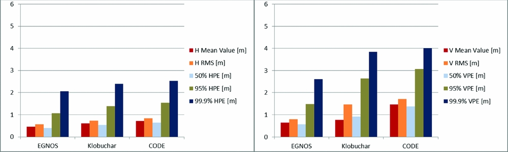
Figure 3. Horizontal (left) and vertical (right) position error deviations from reference on 1-10 June 2014 for the original EGNOS ionospheric correction, the Klobuchar model and the CODE Klobuchar-style predicted ionospheric correction.

Figure 4. Horizontal (left) and vertical (right) position error deviations from reference on 11-20 June 2014 for the original EGNOS ionospheric correction, the Klobuchar model and the CODE Klobuchar-style predicted ionospheric correction.

Figure 5. Horizontal (left) and vertical (right) position error deviations from reference on 21-30 June 2014 for the original EGNOS ionospheric correction, the Klobuchar model and the CODE Klobuchar-style predicted ionospheric correction.
On the basis of the presented accuracy analyses, it can be concluded that the model developed by EGNOS gave the best results of horizontal and vertical accuracy for all examined errors. In the period from 1-10 June 2014, the error characterised by the 95% confidence level for EGNOS model achieved the following values: HPE = 1.1 m, VPE = 1.5 m. In the period from 11-20 June 2014, HPE = 1.0 m and VPE = 1.4 m, and in the period from 21-30 June 2014, HPE = 1.1 m and VPE = 1.4 m. Results that were slightly worse but on the same order of precision were noted for the CODE and Klobuchar model. In the period from 1-10 June 2014, the CODE model reached values of HPE = 1.6 m VPE = 3.1 m, while Klobuchar model achieved values of HPE = 1.4 m and VPE = 2.6 m. In the period from 11-20 June 2014, CODE values were HPE = 1.4 m and VPE = 4.1 m while Klobuchar values were HPE = 1.5 m, VPE = 3.1 m. In the period from 21-30 June 2014, CODE values were HPE = 1.1 m and VPE = 1.6 m while Klobuchar values were HPE = 1.2 m and VPE = 2.8 m.
Nevertheless, the analysis of the average accuracy values obtained in the same periods points to very different conclusions. The best performance is undoubtedly characterised by the original EGNOS ionospheric model. The Klobuchar model gave better results than CODE for both HPE and VPE in the first analysed period, while in the third it was the opposite (CODE was better than Klobuchar). In the second analysed period, HPE was better for the CODE model while VPE was better for Klobuchar. It must be emphasised that all three calculation variants are characterised by the accuracy results meeting the requirements of the SBAS system during the APV-1 approach.
3.2 Integrity analyses
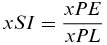
For aviation, the integrity of the information transmitted by the system is more important than accuracy. The presentation of the analysis of the integrity of the GPS/EGNOS positioning is made using position error/protection level (xPE/xPL) for each measurement epoch (Figs 6-8). According to Table 1, for approach operations with vertical guidance (APV-1) the HPE and VPE must not exceed 16/20 m, while HPL and VPL must not exceed 40/50 m respectively. In addition, the position domain Safety Index (SI) must also be examined. Position domain SI is defined as the ratio between the true navigation system error and the corresponding protection level(Reference Vassiley and Vassileva28):
 $$\begin{equation}
xSI = \frac{{xPE}}{{xPL}}
\end{equation}$$
$$\begin{equation}
xSI = \frac{{xPE}}{{xPL}}
\end{equation}$$

Figure 6. Horizontal (left) and vertical (right) positioning accuracy and protection level based on 1-10 June 2014 for: a) the original EGNOS ionospheric correction, b) the Klobuchar model, c) the CODE Klobuchar-style predicted ionospheric correction.

Figure 7. Horizontal (left) and vertical (right) positioning accuracy and protection level based on 11-20 June 2014 for: a) the original EGNOS ionospheric correction, b) the Klobuchar model, c) the CODE Klobuchar-style predicted ionospheric correction.

Figure 8. Horizontal (left) and vertical (right) positioning accuracy and protection level based on 21-30 June 2014 for: a) the original EGNOS ionospheric correction, b) the Klobuchar model, c) the CODE Klobuchar-style predicted ionospheric correction.
where:
-
xSI is the horizontal or vertical safety index,
-
xPE is the horizontal or vertical position error, and
-
xPL is the horizontal or vertical protection level.
There is a potential misleading-information (MI) situation if SI is larger than 0.75. There is real MI every time the instantaneous SI exceeds 1.
Based on the above analyses of the integrity, it can be concluded that the original EGNOS ionospheric model presents the best results in the examined period. During the measurement session recorded on 1-10 June 2014, only 47 epochs did not meet the requirements of the horizontal and vertical APV-1 (protection of levels above of 40 m and 50 m respectively). In the period from 22-30 June 2014, 100% of measurement data meet these requirements. In case of CODE and Klobuchar modes, it can be clearly seen that integrity for APV-1 is not provided. For the CODE model. only 24% of HPL and 8% of VPL meet the requirement of APV-1. For the Klobuchar model, the results are even worse, meeting the APV-1 requirements for 15% of HPL and 1% of VPL. However, it should be emphasised that for both CODE and Klobuchar models 100% of measurement data meets the requirements of NPA (HPL below 556 m).
It should be noted that for some epochs in the EGNOS mode (Fig. 6a) in the first analysed period during Day 2 and 3, there are few peaks of position errors. These epochs were analysed in detail showing that protection levels do not lead to potential MI (SI is less than 0.75).
4.0 CONCLUSION
The subject of the study was to analyse the parameters affecting the quality of positioning using EGNOS in northeastern Poland. The results obtained with the use of the original EGNOS ionospheric model, the Klobuchar model, and the modified Klobuchar-style coefficients model developed by CODE were compared. The accuracy and the values of parameters characterising the integrity of positioning were determined taking into account the three studied variants.
Analyses showed that in the examined period, the original EGNOS model presents best values of position errors and protection levels, meeting the requirements of the integrity of positioning used in APV-1 procedures. The CODE and Klobuchar models are characterised with good accuracy results, which can be applied to users of EGNOS Open Service and NPA operations. These models, however, should not be used in the case of any PA operation, since both HPL and VPL requirements are not met.
The results presented in the studied period do not define the EGNOS performance for the selected location but definitely give insight into trends emerging for the effects of each analysed model of the ionosphere.
ACKNOWLEDGEMENTS
This research is supported by the project ‘RIM WIM – Regionalna Inwestycja w Młodych Naukowców Warmii i Mazur – wzrost potencjału wdrożeniowego wyników prac B + R doktorantów’ co-financed by the EU through the European Social Fund.