I. INTRODUCTION
A horn antenna is simple to design and provides good performance. Generally a three-dimensional horn is used, which is fed using a waveguide [Reference Constantine1]. Waveguide feeding has the advantages of low spurious radiation and less leakage in comparison to the microstrip feed lines and the major disadvantage of these structures is their volume making it difficult to integrate them with Microwave integrated circuit (MIC) components. The substrate-integrated waveguide (SIW) horn is a planar configuration containing all the advantages of classical waveguide horn antenna.
In general, a metamaterial is synthesized by embedding specific metallic structures, which should be periodic, in a medium. So far, a rich variety of metamaterials have been invented and their applications on microwave structures have been studied. It has been proved experimentally and that metamaterials can enhance the gain and directivity when integrated with the antenna structures [Reference Calpino2, Reference Calpino3].
In the present paper, a SIW H-plane horn antenna is designed and the metamaterial structures are embedded on it. The proposed structure combines the advantages of the waveguide horn with the metamaterial resulting in a compact antenna with good radiation performance. The structure is developed on the RT/Duroid substrate with the permittivity (εr) of 2.33, height (b) of 0.8 mm and loss tangent (tanδ) of 0.0012.The simulation is done using Ansoft HFSS software. In addition to the simulation, the antenna is fabricated and the radiation performance is validated through the measurements.
II. DESIGN
A) Design of SIW
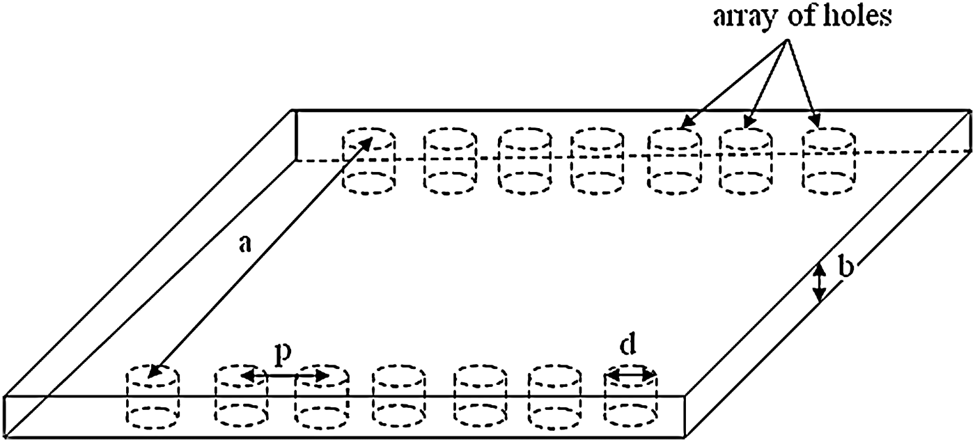
The SIW is a planar equivalent of a waveguide. The side walls of the waveguide are realized using metallic vias to avoid leakage. Initially, the SIW is realized to operate as a feed to the proposed horn antenna. The SIW is designed for a cutoff frequency of 9 GHz with the parameters such as width(a) = 13.6 mm, center-to-center distance between the metallic vias(p) = 2 mm and diameter of the metallic vias(d) = 0.5 mm using the following equations, where w eff is the width of the waveguide [Reference Deslandes and Wu4, Reference Xu and Wu5] (Fig. 1):
Figure 2 shows the simulated S-parameter characteristics of the designed SIW. The response is same as that of the classical waveguide. S 11 is well below −10 dB and S 21 is almost touching the 0 dB line. A satisfactory performance has been achieved by designed SIW for the complete X-band applications.

Fig. 1. Design of a SIW.

Fig. 2. Variation of S-parameter with frequency of SIW.
B) Design of horn antenna
The horn antenna is designed for a resonant frequency of 10.5 GHz. The design parameters are the antenna aperture length, a 1 = 5.5λg and the waveguide aperture length = 0.5 λg.
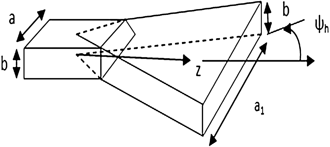
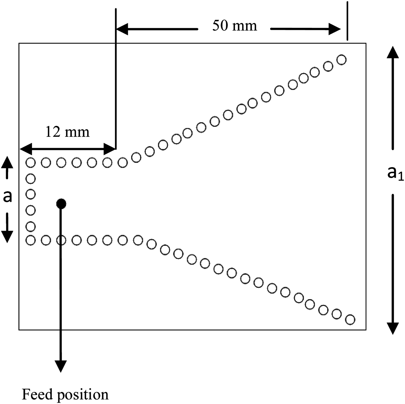
Figure 3 shows the basic waveguide H-plane horn antenna and Fig. 4 shows its SIW equivalent. It is clearly visible that on converting a non-planar structure to a planar structure the design complexity reduces. The antenna is fed using coaxial feed at 4 mm distance from the short end. The position is optimized by several iterations to achieve the best results [Reference Wang, Fang, Zhang and Che6]. The fabricated SIW horn is shown in Fig. 5. The fabrication process is carried out using chemical photolithography and the vias are incorporated in the structure. The S 11 is measured practically using Agilent N5230APNA-L Network Analyzer (Fig. 6). The simulated and experimental S 11 response of the SIW horn antenna is given in Fig. 7. A little mismatch between simulated and measured reflection losses is observed, which may be attributed to fabrication errors. The antenna is resonating at 10.8 GHz both in simulations and measurements and the reflection loss of −18.2 dB (in simulation) and −15.9 dB (in measurement) has been achieved. The current distribution of the SIW H-plane horn antenna at 10.8 GHz is shown in Fig. 8.

Fig. 3. H-plane waveguide horn antenna.

Fig. 4. Horn antenna designed using SIW, a 1 = 60 mm, a = 10 mm.

Fig. 5. Fabricated structure of H-plane SIW horn antenna.

Fig. 6. S-parameter measurement of horn antenna using VNA.

Fig. 7. Simulated and experimental S-parameter of horn antenna.

Fig. 8. Current distribution of SIW H-plane horn antenna.
The radiation pattern and gain of the fabricated antenna is measured using the X-band microwave test setup as shown in Fig. 9. The X-band waveguide horn is used as a transmitter and the designed antenna is used as a receiver.

Fig. 9. Testing of radiation pattern of horn antenna on X-band microwave test bench.
Figure 10 shows the normalized radiation pattern of the horn antenna. The patterns show similar behavior with the experimental pattern showing a loss (1 dB) in comparison to the simulated one. The antenna gives a maximum gain of 5.8 dB at −10°.

Fig. 10. Normalized radiation pattern of horn antenna.
C) Design of metamaterial
Metamaterials are materials that carry unique properties that are not found in natural materials. One such property is the negative value of refractive index, permittivity (εr), and permeability (μr). Such materials are called as left-handed materials (LHM). This increases the gain when introduced in an antenna by reducing the losses due to dielectric and increasing the radiation efficiency.
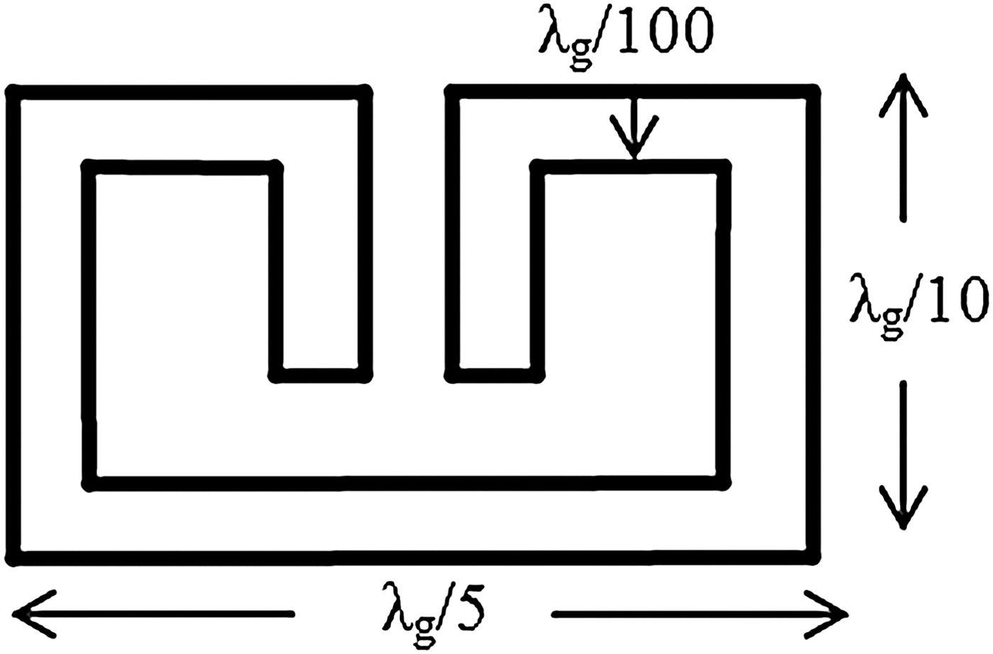
Several structures for metamaterial have been designed in previous years [Reference Grzegorczyk, Kong and Lixin7]. In particular, some that are capable to provide artificial magnetic responses and electric walls, the capacitively loaded loop (CLL) cells, proposed by Erentok et al. [Reference Erentok, Luljak and Ziolkowski8], which allows the creation of an artificial magnetic conductor – AMC, and an artificial electric conductor – AEC. The main aim is to improve of the electric and magnetic fields. The AMC is obtained when a plane wave focuses on the capacitive gap, while the AEC is obtained through the opposite way (Fig. 11).

Fig. 11. Geometry of the designed metamaterial.
The CLL structure is placed inside a waveguide with ports assigned to two of its ends. The response of the waveguide is shown in Fig. 12. This shows acceptable performance at the frequency of interest (10.7 GHz). The value of permittivity (ε) and permeability (μ) can be calculated using following equations (2–5) [Reference Chakraborty and Srivastava9, Reference Chen, Grzegorczyk, Wu, Pacheco and Kong10]:
 $$z=\sqrt {\displaystyle{{\lpar 1+S_{11} \rpar ^2 - \lpar S_{21} \rpar ^2 } \over {\lpar 1 - S_{11} \rpar ^2 - \lpar S_{21} \rpar ^2 }}}\comma$$
where z is the impedance, n represents the refractive index, d is the thickness of the substrate and wave number, k 0 = (2π/λ0), where λ0 is the free-space wavelength.

Fig. 12. S-parameter response of waveguide with CLL.
Figure 13 shows the variation of relative permittivity and relative permeability with frequency of the proposed metamaterial structure. The response shows that the structure is providing a metamaterial behavior in the frequency range of 8.1–11.4 GHz.

Fig. 13. Real and imaginary parts of (a) permittivity and (b) permeability as a function of frequency of the proposed metamaterial.
III. DESCRIPTION OF ANTENNA USING METAMATERIAL
The metamaterial is incorporated as an array of six elements in the flared region of H-plane SIW horn antenna as shown in Fig. 14. Addition of the metamaterial structures to the basic horn antenna, changes the characteristics of substrate material, reducing the losses and by increasing the radiation efficiency.

Fig. 14. Layout and fabricated SIW horn antenna using metamaterial.
The S 11 response for the horn antenna with metamateral is shown in Fig. 15. It is observed that the antenna exhibits dual-band behavior. The initial resonant frequency of the simple horn antenna shifts to the lower side (10.1 GHz) and another resonance is seen at a higher frequency (11.2 GHz). The LHM is incorporated in the SIW H-plane horn antenna by cutting slots in the flaring region. Due to these slots the behavior of current flow on the metallic layer changes resulting in dual-frequency resonance of the antenna. Because of the shifting of first resonance to the lower side, we can say that the size of antenna is reduced. Getting an additional resonance can be useful if the antenna to be used for two different applications. Fig. 16 shows the current distribution of the modified SIW H-plane horn antenna. Fig. 17 shows the normalized radiation pattern at two different frequencies. The direction of the maximum radiation at 10.1 GHz is tilted by −30°. The antenna structure is completely symmetrical, but this could be due to some higher mode excitation at such high frequency. A control can be made on the direction of the electromagnetic radiation by the inherent property of the LHM. The current is more directed (Fig. 16) in the modified horn antenna than the conventional one (Fig. 8). So the LHM acts as a focusing device and hence the gain of the antenna is increased. Also the relative permittivity of the substrate has significant effect on the gain of the antenna. If it is high, then high dielectric loss is encountered and it degrades the antenna gain. So lower the permittivity would minimize the dielectric loss and hence improves the gain of antenna. By making use of the extraordinary property of the metamaterial, the relative permittivity of the substrate is less than unity or negative.

Fig. 15. Simulated and experimental S-parameter of SIW horn antenna using metamaterial.

Fig. 16. Current distribution of modified SIW H-plane horn antenna.

Fig. 17. Normalized radiation pattern of horn antenna using metamaterial. (a) At 10.1 GHz and (b) at 11.2 GHz.
IV. HALF-MODE SIW (HMSIW) HORN ANTENNA
When a SIW operates in the dominant mode, the electric field becomes maximum at the vertical center plane along the direction of propagation; so the center plane can be considered as an equivalent magnetic wall. Based on this idea, SIW can be bisected with a fictitious magnetic wall and each half of SIW becomes an HMSIW [Reference Cheng, Hong and Wu11, Reference Cheng, Hong and Wu12]. So, HMSIW can be simply designed by dividing the SIW into two equal parts. In this paper, an HMSIW horn antenna [Reference Li and Wu13] is introduced. The proposed antenna is fed by a coaxial feed line unlike the previous works on HMSIW components which are fed using microstrip line. The microstrip feeding suffers from parasitic radiation (which may degrade the radiation pattern of the horn antenna in the H-plane) and high conductor loss at higher frequencies, and so a coaxial line is used as the feed in order to avoid these imperfections. The aperture length of the SIW H-plane horn antenna is 60 mm and width of the waveguide portion is 10 mm. The implementation of HMSIW technique will reduce the aperture length to 30 mm and the width of the waveguide portion to 5 mm. Size of the rectangular unused portion of HMSIW antenna is 68 mm × 40 mm. This region does not have any metallic layer and so it does not affect the radiation performance of the antenna and also reduces the conductor loss. The proposed antenna is simulated with HFSS software and its radiation properties are investigated.
The antenna structures (layout and fabricated) are shown in Fig. 18. It is clearly visible that the antenna size is reduced by half. This also reduces the complexity of the design. Fig. 19 shows the S-parameter characteristics of the proposed horn antenna. The resonant frequency of the antenna slightly shifts to the lower side at about 10.6 GHz in both simulation and measurement. The radiation pattern is shown in Fig. 20. The aperture length of HMSIW H-plane horn antenna is exactly half of the conventional SIW horn antenna. The reduced aperture length of the HMSIW horn antenna might be the reason of spreading of the radiation pattern.

Fig. 18. Layout and fabricated HMSIW horn antenna. (a) Layout and (b) fabricated structures.

Fig. 19. Simulated and experimental S-parameter of HMSIW horn antenna.

Fig. 20. Normalized radiation pattern of HMSIW horn antenna.
V. HMSIW WITH METAMATERIAL
Metamaterial is incorporated on the HMSIW as well. Array of three structures is placed along the radiating aperture (Fig. 21). S-parameter response of the HMSIW is shown in Fig. 22. Dual-band performance is achieved similar to the full-mode structure. Two resonances at 10.4 and 11.3 GHz are achieved. The normalized radiation pattern at these two frequencies is shown in Fig. 23. It is clearly evident that the pattern has improved and no prominent side lobes are visible in comparison to the pattern of the antenna without metamaterial.

Fig. 21. Layout and fabricated HMSIW horn antenna using metamaterial. (a) Layout and (b) fabricated structure.

Fig. 22. Simulated and experimental S-parameter of HMSIW horn antenna using metamaterial.

Fig. 23. Normalized radiation pattern of HMSIW horn antenna using metamaterial. (a) At 10.4GHz and (b) at 11.3GHz.
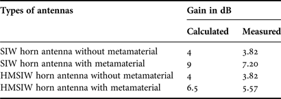
The presence of the side lobes in the radiation pattern of HMSIW H-plane horn antenna is due to the reduction in the aperture length as mentioned in Section IV. Using the extraordinary property of LHM the current flow is more directed in the modified HMSIW H-plane horn antenna compared to the conventional HMSIW horn antenna. More directionality in the current flow might suppress the spreading or side-lobe levels and hence improve the gain (Table 1).
Table 1. Calculated and simulated values of gain of different types of antennas

VI. CONCLUSION
From the discussions above, it can be concluded that a high-gain small-sized horn antenna is designed on SIW using metamaterial. In the application where high gain is required and size is not a constraint, the SIW H-plane horn antenna with metamaterial can be used. In places where compactness is a requirement, the half-mode horn antenna with metamaterial can be used with slightly lower gain.


