


1. Introduction
This work presents an investigation of the coupling behaviour of underexpanded supersonic circular twin jets. Supersonic jets produce intense acoustic radiation, which is sometimes further amplified in the twin-jet configuration. The amplified acoustic radiation of twin jets has led to nozzle and empennage structure fatigue damage in some high-speed aircraft with the twin-engine configuration, including the B-1B (Berndt Reference Berndt1984) and the F-15 (Seiner, Manning & Ponton Reference Seiner, Manning and Ponton1986).
One major source of acoustic radiation in these jets stems from a self-reinforcing aeroacoustic feedback process called jet screech (Powell Reference Powell1954; Tam Reference Tam1995). Screech occurs in shock-containing supersonic jets as a result of the interaction between coherent vortical structures (CVS) produced in the shear layer of the jet and the jet shock cells. This interaction produces intense acoustic waves that propagate most strongly in the upstream direction via two known mechanisms: free-stream acoustic waves (Powell Reference Powell1954) or guided modes of the jet (Edgington-Mitchell et al. Reference Edgington-Mitchell, Jaunet, Jordan, Towne, Soria and Honnery2018a; Gojon, Bogey & Mihaescu Reference Gojon, Bogey and Mihaescu2018). Upon striking the jet nozzle lip, the waves scatter and perturb the thin jet-exit shear layer. Under certain conditions they produce new CVSs and thus complete the feedback process (Edgington-Mitchell et al. Reference Edgington-Mitchell, Oberleithner, Honnery and Soria2014b). A summary of the present understanding of jet screech is provided by Edgington-Mitchell (Reference Edgington-Mitchell2019).
Screech is associated with periodic oscillation modes of the jet column. Within twin-jet studies, toroidal, helical and flapping modes of the individual jets have been observed (Seiner et al. Reference Seiner, Manning and Ponton1986; Kuo, Cluts & Samimy Reference Kuo, Cluts and Samimy2017b), which then couple symmetrically or anti-symmetrically about the symmetry plane of the twin-jet system. The screech mode of the individual jets and the nature of the coupling between them are associated with a particular location within the jet spacing and nozzle pressure ratio parameter space. Correspondingly, moving through the parameter space results in the presentation of different coupling modes. Despite numerous studies observing clear coupling in twin-jet systems since the mid 1980s, the process of mode selection, transition between modes and the coupling mechanisms remain poorly understood (Panickar, Srinivasan & Raman Reference Panickar, Srinivasan and Raman2004, Reference Panickar, Srinivasan and Raman2005; Srinivasan et al. Reference Srinivasan, Panickar, Raman, Kim and Williams2009; Raman, Panickar & Chelliah Reference Raman, Panickar and Chelliah2012; Knast et al. Reference Knast, Bell, Wong, Leb, Soria, Honnery and Edgington-Mitchell2018). The coupling behaviour has been observed to be a function of nozzle pressure ratio (NPR), nozzle spacing, boundary-layer thickness, shear-layer growth rate, nozzle geometry and the acoustic environment (Wlezien Reference Wlezien1989; Morris Reference Morris1990; Alkislar et al. Reference Alkislar, Krothapalli, Choutapalli and Lourenco2005). NPR is the ratio of nozzle stagnation pressure at the nozzle exit ( $p_0$) to ambient pressure in the exhaust region (
 $p_\infty$),
  $\mathrm {NPR} = p_{0}/p_{\infty }$. An analogue to NPR is the ideally expanded Mach number,
  $M_{j}$. The non-dimensional spacing between the jets is represented by
  $s/D$, where
  $s$ is the spacing between the jet centres, and
  $D$ is the jet-exit diameter. The effect of jet temperature ratio on twin-jet coupling remains an open topic for investigation. The addition of heat is generally associated with a suppression of screech in single jets (Shen & Tam Reference Shen and Tam2000), although under certain conditions it has also been seen to amplify the acoustic tones (Gojon et al. Reference Gojon, Baier, Gutmark and Mihaescu2017; Gojon, Gutmark & Mihaescu Reference Gojon, Gutmark and Mihaescu2019). Strong coupling associated with the production of screech tones was observed in the two primary full-scale aircraft studies (Berndt Reference Berndt1984; Seiner et al. Reference Seiner, Manning and Ponton1986), indicating that in full-scale systems, screech is still present in heated twin-jet configurations.
Typically, NPR and  $s/D$ are the primary independent variables that govern coupling behaviour in twin jets; within certain NPR and
  $s/D$ ranges, different coupling modes are observed. The term mode staging is used to describe the discontinuous changes in mode shape and tone frequency at points in the parameter space. Several existing studies have focused on characterising the behaviour and mode staging of twin-jet systems as a function of these parameters (Seiner et al. Reference Seiner, Manning and Ponton1986; Wlezien Reference Wlezien1989; Raman Reference Raman1998; Knast et al. Reference Knast, Bell, Wong, Leb, Soria, Honnery and Edgington-Mitchell2018; Panickar et al. Reference Panickar, Srinivasan and Raman2005; Srinivasan et al. Reference Srinivasan, Panickar, Raman, Kim and Williams2009). The tendency of the jets to couple about the symmetry plane has facilitated the use of opposing microphones on each side of the twin-jet system to study the coupling behaviour. Acoustic measurements in this style, alongside a range of qualitative optical techniques, have been applied to a wide range of laboratory-scale twin-jet systems (Wlezien Reference Wlezien1989; Shaw Reference Shaw1990; Zilz & Wlezien Reference Zilz and Wlezien1990; Umeda & Ishii Reference Umeda and Ishii2001; Alkislar, Krothapalli & Lourenco Reference Alkislar, Krothapalli and Lourenco2003; Panickar et al. Reference Panickar, Srinivasan and Raman2004; Kuo, Cluts & Samimy Reference Kuo, Cluts and Samimy2016a,Reference Kuo, Cluts and Samimyb, Reference Kuo, Cluts and Samimy2017a; Bell et al. Reference Bell, Soria, Honnery and Edgington-Mitchell2017; Cluts, Kuo & Samimy Reference Cluts, Kuo and Samimy2017; Kuo et al. Reference Kuo, Cluts and Samimy2017b; Goparaju & Gaitonde Reference Goparaju and Gaitonde2018). While acoustic measurements are relatively easy to obtain, they are not always easy to interpret, and measurements of the hydrodynamic field are far more difficult to acquire. These challenges as well as advances in computational capabilities have motivated numerical approaches to the problem (Brès, Ham & Lele Reference Brès, Ham and Lele2013; Goparaju & Gaitonde Reference Goparaju and Gaitonde2018). However, the sensitivity of resonant systems to boundary conditions presents its own set of challenges (Weightman et al. Reference Weightman, Amili, Honnery, Edgington-Mitchell and Soria2019). From a mechanistic perspective, the tendency of these jets to couple together has been demonstrated theoretically via vortex-sheet and finite-thickness stability approaches (Morris Reference Morris1990; Du Reference Du1993; Du Reference Du2003), although these studies did not include the upstream component of the resonance process.
Seiner et al. (Reference Seiner, Manning and Ponton1986) provided a detailed canonical experimental investigation of axisymmetric supersonic twin jets. The experimental set-up consisted of 1/40th scale F-15 nozzles with a diameter of  $D=1.57$ cm, and inter-nozzle spacing of
  $s/D=1.9$. They swept the parameter space through
  $1.89 \leqslant \mathrm {NPR} \leqslant 7.8$ (
 $1.0 \leqslant M_j \leqslant 2.0$) and attempted to identify the coupling shape and azimuthal mode number associated with each high-amplitude acoustic peak. Mode staging (based on peak frequency) reminiscent of an isolated jet was observed, although with fewer stages that extended over larger pressure ranges with much higher amplitudes. The oscillations of the jets were observed to be strongly coupled about the symmetry plane via both a phase-locked schlieren technique, and measurements of coherence from opposing microphones.
Raman (Reference Raman1998) examined the coupling of twin supersonic high-aspect-ratio rectangular jets, with major axes normal to the symmetry plane. Opposing microphones and phase-locked acoustically triggered schlieren were used to characterise the coupling modes of the system. A parameter sweep was performed across  $1.89 \leqslant \mathrm {NPR} \leqslant 4.6$ (
 $1.0 \leqslant M_j \leqslant 1.65$) and
  $5.5 \leqslant s/D \leqslant 15$, which identified three distinct coupling modes. With increasing
  $M_j$, an anti-symmetric mode followed by a symmetric mode were observed. Unlike axisymmetric jets, both coupling modes involved a flapping of the jet in the symmetry plane direction, driven by the tendency of high-aspect-ratio jets to flap about their major-axis plane between the jets. For the range of jet spacings considered, as NPR was increased the first coupling mode was described by the authors as a ‘weak complex interaction’, where multiple strong acoustic tones exist but phase-locking with the schlieren system was not possible.
Panickar et al. (Reference Panickar, Srinivasan and Raman2004) further investigated the propensity for twin jets to couple and the physical interactions that allowed them to do so. They studied rectangular oblique jets, measuring in what portions of the parameter space they coupled and comparing this with stability analysis to find the stability margin required to enable coupling. General agreement was found between stability analysis predictions and the experimental observations. Panickar et al. (Reference Panickar, Srinivasan and Raman2005) and Srinivasan et al. (Reference Srinivasan, Panickar, Raman, Kim and Williams2009) sought a quantitative indicator for when a coupled jet might soon switch to another mode. The indicator was based on measuring the number of nonlinear interactions between frequencies in the time-averaged acoustic spectra using cross-bi-coherence. Nonlinear interactions were detected in jet acoustic recordings by computing the cross bi-coherence of two simultaneously recorded microphone signals and measuring the number of peaks and their cluster density in the resulting spectra. General agreement between the number of nonlinear interactions and proximity to the mode-switch point was found.
Knast et al. (Reference Knast, Bell, Wong, Leb, Soria, Honnery and Edgington-Mitchell2018) revisited the circular twin jet in a canonical set-up similar to Seiner et al. (Reference Seiner, Manning and Ponton1986), comparing experimental data to the frequency prediction relations developed by Powell (Reference Powell1953), Shen & Tam (Reference Shen and Tam2002) and Panda (Reference Panda1999). Within the study, Knast et al. examined the  $s/D = 3$ twin-jet spacing using time-resolved and high-resolution schlieren photography, and opposing microphones. In the initial characterisation of the twin-jet modes, Knast et al. observed parameter space regions of unambiguous symmetric and anti-symmetric coupling from the cross power spectral density (CPSD) measurement of phase between the opposing microphones. Additionally, a region of the NPR space (
 $3.4 \leqslant \mathrm {NPR} \leqslant 4.4$) between the symmetric and anti-symmetric modes was found to exhibit an erratic phase relation between the jets. Curiously, the region also maintained high coherence between the acoustic signals (
 ${\geqslant }0.7$). High-speed imagery failed to provide further clarity. Spatial correlation maps of high-resolution schlieren images were similarly inconclusive. The erratic phase region was also found to exist at the
  $s/D=6$ spacing, where it persisted from
  $2.75 \leqslant \mathrm {NPR} \leqslant 4.75$ between two symmetric coupling modes.
Bell et al. (Reference Bell, Soria, Honnery and Edgington-Mitchell2018) investigated the velocity field of the  $s/D=3$ circular twin jet using particle image velocimetry (PIV). Spatial correlations of velocity were used to indicate the dominant coupling mode at conditions with both steady and erratic phase relations between the jets. The velocity correlations exhibited a clear anti-symmetry for the condition with steady acoustic phase, but no clear mode shape in the erratic phase region. Furthermore, the anti-symmetric mode showed a strong standing wave in the jets’ near field, whereas no standing wave was observed at the condition with erratic phase relation. In this paper the operating range with an erratic phase relation will be termed the ‘phase anomaly’.
The results of Panickar et al. (Reference Panickar, Srinivasan and Raman2005) and Srinivasan et al. (Reference Srinivasan, Panickar, Raman, Kim and Williams2009) revealed the signature of potential nonlinear interactions at operating conditions adjacent to mode staging points. It remains unclear whether the phase anomaly observed in both Knast et al. (Reference Knast, Bell, Wong, Leb, Soria, Honnery and Edgington-Mitchell2018) and Bell et al. (Reference Bell, Soria, Honnery and Edgington-Mitchell2018) is the signature of nonlinear interaction. The region is book ended by a symmetric coupling at low pressure, and an anti-symmetric coupling at higher pressure ratios. Thus the phase anomaly being the result of a nonlinear competition between two coupling modes is plausible. However, as little is presently known about the behaviour of the jets in this region, it is difficult to comment further at this point.
In this paper, the authors provide an explanation for the hydrodynamic and acoustic behaviour that characterises the phase anomaly region. First, the acoustic near field of the twin-jet system is interrogated using several methods of analysis applied to acoustic data obtained from a pair of microphones. Then the hydrodynamic field associated with different coupling behaviour of the twin-jet systems is assessed using a modal decomposition and conditional sampling of PIV data.
2. Experiments and methodology
The results of experiments in three separate facilities are examined within this work. Two of the three have featured in other publications. The data underpinning the analysis in this paper are drawn from the acoustic measurements of Knast et al. (Reference Knast, Bell, Wong, Leb, Soria, Honnery and Edgington-Mitchell2018) and the velocity data described in Bell et al. (Reference Bell, Soria, Honnery and Edgington-Mitchell2018).
2.1. Facility one
2.1.1. Opposing microphone study
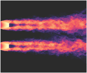
This set of experiments were conducted in the Laboratory for Turbulence Research in Aerospace and Combustion (LTRAC) schlieren jet facility at Monash University. The experimental set-up is shown in figure 1. Compressed air at 298 K is supplied directly to the plenum chamber, which contains a honeycomb section and wire mesh screens to homogenise and condition the flow. Compressed air exhausts from twin converging circular nozzles with an exit diameter of  $D = 10$ mm, a nozzle-lip thickness of 1.5 mm and a non-dimensionalised spacing of
  $s/D = 3.0$. The flow at the exit is choked (exit Mach number,
  $M_e = 1$) with a jet exit velocity
  $U_e \approx 310\ \textrm {m}\ \textrm {s}^{-1}$. The Reynolds number based on the nozzle exit conditions is approximately
  $7.8 \times 10^5$ for
  $\mathrm {NPR} = 4.6$ and
  $8.5 \times 10^5$ for
  $\mathrm {NPR} = 5.0$.

Figure 1. Schematic of the acoustic set-up, adapted from Knast et al. (Reference Knast, Bell, Wong, Leb, Soria, Honnery and Edgington-Mitchell2018).
Acoustic measurements were obtained with a GRAS type 46BE  $1/4''$ preamplified microphone with a frequency range of 20 Hz to 100 kHz. The microphone amplitude coefficient was referenced against a GRAS type 42AB sound level calibration unit. The signal output from the microphone was recorded on a National Instruments DAQ at a sample rate of 250 kHz to prevent aliasing and a signal resolution of 16 bits. The opposing microphones were positioned 8
  $D$ radially from the closest nozzle lip and an uncertainty analysis was performed to ensure that microphone positioning error (and thereby phase response) was minimised. Millimetre microphone positional accuracy was achieved that corresponds to a phase error of approximately
  ${\pm } 5^{\circ }$ (considering a screech frequency of 15 kHz,
  $340\ \textrm {m}\ \textrm {s}^{-1}$ ambient speed of sound corresponding to a wavelength of the order of 20 mm). Microphone measurements were conducted over the jet pressure range of
  $2.0 \leqslant \mathrm {NPR} \leqslant 5.0$ in steps of 0.05 NPR. This corresponds to an ideally expanded Mach number range of
  $1.05 \leqslant M_j \leqslant 1.71$ assuming a constant ratio of specific heats of air of 1.4. The lower and upper
  $M_j$ resolution of
  $2.04 \times 10^{-2}$ and
  $6.58 \times 10^{-3}$ respectively as
  $M_j$ does not map to NPR linearly due to temperature changes. 500 k samples were recorded simultaneously on both microphones and five measurements were ensemble averaged per NPR.
2.1.2. Schlieren dataset
A short comparison with high-speed schlieren photography is presented at the end of this work as a physical reference to confirm the analysis techniques. The examination of its statistics was presented in Knast et al. (Reference Knast, Bell, Wong, Leb, Soria, Honnery and Edgington-Mitchell2018). A Toepler Z-Type schlieren system was used to image the twin supersonic jet, which was not simultaneously recorded with the acoustic recordings mentioned previously. Two mirrors, each of focal length 2032 mm, were used to create a collimated light path through the test section. Only the density gradient in the streamwise direction ( $\delta \rho /\delta x$) is presented within this work. A Shimadzu HPV-1 camera was used to obtain high-speed images of the twin jet. The camera has a resolution of
  $320 \times 260$ pixels and can capture 102 images at an acquisition speed of up to 1 million frames per second at an exposure of
  $0.25\ \mathrm {\mu }\textrm {s}$.
2.2. Facility two
2.2.1. Particle image velocimetry
The experiments were conducted in the Laboratory for Turbulence Research in Aerospace and Combustion (LTRAC) supersonic particle image velocimetry jet facility also at Monash University. The PIV results within this paper were also examined in previous work (Bell et al. Reference Bell, Soria, Honnery and Edgington-Mitchell2018). The experimental PIV set-up is shown in figure 2. Air at approximately 298 K is supplied directly to a mixing chamber where the jets are uniformly seeded with smoke particles from a Viscount 1300 smoke generator. Only one smoke source was needed for both jet core and ambient fluid measurements as after a short time the smoke particles completely filled the measurement facility. The mixing chamber is connected to the plenum chamber, which contains a honeycomb section and wire mesh screens to homogenise and condition the flow. The exhausted flow is imaged inside the PIV enclosure, which is  $60 \times 60 \times 200$ diameters in size. The walls of the enclosure are not acoustically treated. The nozzle assembly used in facility one is compatible with this experimental facility and used for these experiments for consistency.

Figure 2. Experimental PIV set-up.
The LTRAC supersonic schlieren and supersonic PIV jet facilities are similar, but not identical. The same nozzles were used on both facilities, with the same plenum design, but with different boundary conditions for the acoustic field, namely:
(i) The PIV facility consists of an enclosure surrounding the jet flow to prevent the seeded flow from entering the laboratory. The enclosure measures
 $60 \times 60 \times 200~D$ and has hard Perspex walls. These walls are strong acoustic reflectors.
(ii) In the PIV facility the plenum face where the nozzles are mounted sits nearly flush with the base of the enclosure. There is thus also a different upstream reflection condition in this facility; the facility for the acoustic measurements has no such mounting.

A set of experiments in a third facility were undertaken to further elucidate the facility sensitivity of the results. These experiments are described in appendix B.
3. Ensemble-averaged spectral analysis of the acoustic field
Knast et al. (Reference Knast, Bell, Wong, Leb, Soria, Honnery and Edgington-Mitchell2018) extracted the phase difference between screech tones obtained by opposing microphones via CPSD. While many NPR conditions produced a highly coherent phase difference of either 0 or  $180^{\circ }$, a high phase variance between
  $3.4 \leqslant \mathrm {NPR} \leqslant 4.4$ (figure 7 in Knast et al. Reference Knast, Bell, Wong, Leb, Soria, Honnery and Edgington-Mitchell2018) was observed. These results are first reconsidered here, before the application of other analysis techniques.
Figure 3 presents a waterfall plot of individual power spectral density (PSD) amplitudes stacked as a continuous function of NPR. The vertical axis represents the Strouhal number, which is calculated from the acoustic frequency  $f$, ideally expanded exit diameter
  $D_j$, and the ideally expanded exit velocity
  $u_j$. A single fundamental screech peak is evident across most of the NPR range as narrow-band high dB scars with additional harmonics. The discontinuities in screech tone and general spectra at
  $\mathrm {NPR}=3.4$ and 4.4 suggest mode switches.

Figure 3. Waterfall plot of PSD for  $s/D=3$. Data from Knast et al. (Reference Knast, Bell, Wong, Leb, Soria, Honnery and Edgington-Mitchell2018). The high-intensity narrow-band lines indicate screech tones. Discontinuous frequency changes in the screech tone indicate a change of twin-jet mode.
Where Knast et al. (Reference Knast, Bell, Wong, Leb, Soria, Honnery and Edgington-Mitchell2018) considered only the phase at the peak-amplitude frequency, instead the authors here consider phase and coherence for all frequencies. CPSD is used to provide this estimate of sample-averaged coherence and phase. To reduce random error, the records are broken into  $2^{13}$ sample sub-records and ensemble averaged
 \begin{equation} \hat{G}_{xy} (f) = \frac{2}{n_d T} \sum_{i=1}^{n_d} {X_i}^* (f) Y_i (f), \end{equation}
where  $f$ is the independent variable representing frequency,
  $n_d$ is the number of sub-records of length
  $T$,
$T$,  ${X_i}^* (f)$ is the complex conjugate of the finite Fourier transform of the first signal and
  $Y_i (f)$ is the finite Fourier transform of the second signal;
  $\hat {G}_{xy}$ is the complex CPSD estimate. The measure of coherence between the signals is defined by (3.2):
 \begin{equation} \hat{C}_{xy} (f) = \frac{ |G_{xy} (f) |^2 } { G_{xx} (f) G_{yy} (f) }. \end{equation}
Phase is calculated from the CPSD as the angle of the two-component complex-valued function, (3.3), as a function of frequency:
 \begin{equation} \hat{\theta}_{xy} (f) = \tan^{-1} \frac{ Im (G_{xy} (f)) } { Re (G_{xy} (f)) }. \end{equation}
Contours of coherence and phase from the CPSD are presented in figures 4(a) and 4(b) respectively. Figure 4(a) demonstrates the presence of additional highly coherent tones, which have relatively low acoustic amplitude. Regions exhibiting high coherence and low amplitude are particularly concentrated in the phase anomaly region.

Figure 4. Cross power spectral density results between opposing microphones from the experiments performed in Knast et al. (Reference Knast, Bell, Wong, Leb, Soria, Honnery and Edgington-Mitchell2018). (a) Waterfall combination plot of cross-spectral density coherence. (b) Waterfall combination plot of cross-spectral density phase given that coherence ${\geqslant }0.7$.
The magnitude of the phase wrapped between 0 and  $180^{\circ }$ is presented in figure 4(b), excluding all frequencies where coherence is less than 0.7.
There are three coherent (non-harmonic) tones evident in figure 4(b), whose frequency varies continuously as a function of  $\mathrm {NPR}$. When tonal frequency varies smoothly as a function of pressure ratio, this is generally indicative that the changes in frequency are caused only by variations in convection velocity and shock spacing, both of which are continuous functions of pressure ratio. A universal explanation for discrete changes in frequency in these resonant flows, i.e. the modal staging described in § 1, is still lacking, but can be attributed to several mechanisms. Firstly, the growth rate of the various azimuthal modes is a function of Mach number (and thus NPR); at certain operating conditions a change in which azimuthal mode is dominant will produce a change in tonal frequency. In twin-jet systems, this change may be a change in the coupling between the jets, rather than a change in the azimuthal mode of the individual jets (Rodríguez, Jotkar & Gennaro Reference Rodríguez, Jotkar and Gennaro2018). Secondly, a change in the number of contemporaneous vortical structures and acoustic waves can produce a discrete change in frequency, as demonstrated in Gao & Li (Reference Gao and Li2010); such a change may be driven by a change in effective source location (Mercier, Castelain & Bailly Reference Mercier, Castelain and Bailly2017). Lastly, a change in the nature of the upstream component of the resonance (from free-stream acoustic wave to guided jet mode) could potentially result in a change in frequency, as has been suggested in Shen & Tam (Reference Shen and Tam2002), but this has not been demonstrated conclusively in practice. In this document, we will use the term ‘process’ to refer to an aeroacoustic feedback loop producing a tone whose frequency varies continuously as a function of operating condition, as labelled in figure 5. This smooth variation indicates that across a range of operating conditions the mechanism producing the tone in question is characterised by the same azimuthal modes, coupled in the same way, with the same effective source location. Process 1 is evident across most of the NPR range, and at low pressures is associated with a
  $180^{\circ }$ phase offset. Process 2 begins at approximately
  $\mathrm {NPR}=3.5$ and continues until the end of the range, and is not associated with a particular phase. Process 3 begins at
  $\mathrm {NPR}=4.4$ with a zero degree phase offset and extends until the end of the measured NPR range.

Figure 5. Coherence vs. NPR marked with processes where acoustic temporal information is examined with the bandpass Hilbert technique.
Examining the phase along processes 1 and 2, it is apparent why the region in which these processes are both active has previously resisted classification on the basis of phase; within the phase anomaly region ( $3.4 \leqslant \mathrm {NPR} \leqslant 4.4$) two processes with highly varying phase are evident.
Small changes in NPR are associated with large (and seemingly random) changes in the phase associated with the peak tone, and at some conditions multiple high-coherence frequency bands are evident. Therefore, the reporting of CPSD phase originating from a single frequency in this region is likely to return spurious values despite the high coherence.
The analysis in Knast et al. (Reference Knast, Bell, Wong, Leb, Soria, Honnery and Edgington-Mitchell2018), and that presented here so far, considers phase and amplitude only in an ensemble-averaged sense. The analysis is now extended to include temporal variation in the signal to identify whether the phase anomaly is a transient phenomenon.
4. Time-resolved analysis of the acoustic field
A range of techniques exist to extract time-resolved quantities from acoustic data. A short-windowed Fourier transform provides insufficient temporal resolution and was excluded. Based on a consideration of the relative strengths of Hilbert and wavelet based approaches (Huang Reference Huang2014), a Hilbert approach was selected for the present data. The wavelet transform has also been shown to be an effective means of examining intermittency and mode switching in resonant jets (Mancinelli et al. Reference Mancinelli, Jaunet, Jordan and Towne2019). Here, a combination of bandpass filtering with the Hilbert transform is used to gain access to the instantaneous signal amplitude and phase as a function of time.
The Hilbert transform of a single process is found from the convolution integral in (4.1),
 \begin{equation} \tilde{x}(t) = x(t)\ast(1/{\rm \pi} t), \end{equation}
where  $\tilde {x}(t)$ is the Hilbert transform of the original signal
  $x(t)$,
  $\ast$ is the convolution integral and
  $t$ is time. The Hilbert transformed variable,
  $\tilde {x}$, can be used to represent a new analytic signal of the original process, as in (4.2),
 \begin{equation} z(t) = x(t) + j \tilde{x}(t), \end{equation}
where  $z(t)$ is the new analytic function,
  $x(t)$ remains the original function represented in the real domain and the Hilbert transform is represented in the complex domain via the complex number
  $j$;
$j$;  $z(t)$ can also be represented in polar notation,
 \begin{equation} z(t) = A(t) \,\textrm{e}^{\,j \theta(t)}, \end{equation}
where  $A(t)$ is the amplitude of the complex value,
 \begin{equation} A(t) = [x^2(t) + \tilde{x}^2(t)]^{1/2}, \end{equation}
and  $\theta (t)$ is the phase of the complex value,
 \begin{equation} \theta(t) = \tan^{-1} \left[ \frac{\tilde{x}(t)}{x(t)} \right]. \end{equation}
 Here,  $A(t)$ and
  $\theta (t)$ represent the process amplitude envelope and phase angle as a function of time, and hence provide access to the temporal information of the input process.
The difference between the two phase signals is evaluated to calculate phase between the two microphones,
 \begin{equation} {\rm \Delta} \theta(t) = \theta_1(t) - \theta_2(t). \end{equation}
The Hilbert transform has the advantage that it can operate on nonlinear and non-stationary signals provided that it operates on a single statistical signal. In this context, a statistical signal is a stochastic one-dimensional record corresponding to a repeatable input-output system. This makes the application to jet noise challenging, as within a jet-noise acoustic spectrum there are multitudes of different processes and other noise generation mechanisms contributing to the far-field measured sound. A mechanism that extracts the relevant processes from the raw signal is required to enable the application of the Hilbert transform individually to these processes. A bandpass filter was used to filter the acoustic signals surrounding the process frequencies. A width of 200 Hz was found sufficient to ensure that the tones do not overlap and the peak frequency is captured.
Within figure 4(a) some regions where multiple coherent peak frequencies are observed to exist. To determine the time-based physical processes along each of the contiguous screech tones; the bandpass Hilbert analysis is applied to each of the frequencies separately. From each application at a particular frequency, a time trace of phase and signal amplitude envelope is extracted. These quantities are examined first.
4.1. Examining transient phase and amplitude
The time scales on which the flow operates resulted in the raw Hilbert bandpass signals being too laborious to examine. Instead, ensemble statistics and histogram representation provided a clearer view into the signal characteristics. Histograms of instantaneous phase and amplitude are shown in figure 6 for the separate processes. Process 1 persists across most of the NPR range as shown in figures 6(a) and 6(b). Between  $2.3 \leqslant \mathrm {NPR} \leqslant 3.0$ the phase distribution is wide and centred on 180 degrees. Here a ‘wide’ distribution is defined as where the distribution standard deviation is greater than
  $20^{\circ }$ for phase, and 3 dB for amplitude; plots of standard deviation of the distributions are included in appendix C. Around
  $\mathrm {NPR} = 3.0$, process 1 exhibits a phase centred on
  $180^{\circ }$, and the distribution of both the phase and amplitude is narrow. The amplitude within this region corresponds to the highest acoustic intensity within the NPR range. Beyond
  $\mathrm {NPR} = 3.5$ the process transitions to lower amplitude and a wider phase without a clear distribution centre. It shall be investigated in the following sections whether the process continues to exist at these higher
  $\mathrm {NPR}$ values. However, at this stage there is a faint process 1 signal in the coherence waterfall (figures 3 and 5), so the authors presume that it does exist at the higher NPRs in a reduced capacity. Process 2 (figures 6c and 6d) begins around
  $\mathrm {NPR} = 3.5$, (the point where process 1 rapidly reduces in amplitude and increases in phase variance). Process 2 exhibits a wider distributed phase centred on 180 degrees. The amplitude is more widely distributed than the other processes, which spreads histogram bin counts over a wider range. Hence the normalised histogram results in lower probability density estimates for process 2 compared to process 1 or 3. Around
  $\mathrm {NPR} = 3.9$, the phase and amplitude distributions of both processes 1 and 2 change without a significant change in observed frequency. Process 1 is observed to become very wide in its phase distribution with lower amplitude. For
  $\mathrm {NPR} \geqslant 4.1$, the phase distribution of process 2 somewhat narrows around a peak of 180 degrees, with a corresponding increase in acoustic amplitude. Beyond
  $\mathrm {NPR} = 4.4$, process 3 becomes evident (figures 6e and 6f), exhibiting a narrow phase distribution centred on zero degrees phase, with a narrow distribution of high amplitude. The observations are summarised in table 1.

Figure 6. Joint probability density functions of phase and amplitude as a function of  $\mathrm {NPR}$ for processes 1, 2 and 3. Colour bars represent histogram probability density. The histogram is normalised such that the sum of the probabilities for a given pressure ratio is 1 and the units are 1/degree and 1/dB for phase and amplitude respectively. (a) Process 1 phase. (b) Process1 amplitude. (c) Process 2 phase. (d) Process 2 amplitude. (e) Process 3 phase. (f) Process 3 amplitude.
Table 1. The letters N/W correspond to narrowly/widely statistically distributed, respectively, 0 and 180 correspond to observed centre of the phase distribution and UC corresponds to an uncentred distribution.

Narrow distributions of phase and amplitude are generally observed together. Additionally, when the amplitude is narrow, the corresponding process generally shows constant amplitude. Knast et al. (Reference Knast, Bell, Wong, Leb, Soria, Honnery and Edgington-Mitchell2018) identified that coupling oscillation was strongest where the phase is well defined ( $3.0 \leqslant \mathrm {NPR} \leqslant 3.4$). Over this NPR range, the most intense screech tones are observed in the present data. This is consistent with the findings of Seineret al.(Reference Seiner, Manning and Ponton1986), where the coupling was found to increase the acoustic amplitude beyond the summation of two single screeching jets when the coupling motion was strong.
Some of the wide amplitude distributions exhibit a long tail towards lower values. Do the lower values indicate that the tone becomes interrupted? This is considered in the following section.
4.2. Examining screech interruptions and intermittency on an individual jet
In regions where the amplitude is widely distributed, the distribution is strongly skewed, with a long tail of lower amplitudes. This long tail indicates that there are events where the screech tone is either damped or entirely interrupted. To quantify the frequency of these ‘quiet’ events, a dB threshold was defined as when the amplitude drops below 5dB of its mean value. The technique is discussed in appendix A. Figure 7 shows the total interruption duration as a percentage of total signal length. The regions of wide phase and amplitude distribution generally overlap with regions of higher interruption rate (high interruption rate is considered 20 % here). An exception is found for  $3.5 < \mathrm {NPR} < 3.9$, where there is widely distributed phase on process 1 but it is accompanied by a relatively low interruption rate (approximately 2 %). This interruption rate then increases when
  $\mathrm {NPR} > 3.9$.

Figure 7. Percentage of acoustic interruptions detected within the Hilbert amplitude acoustic signals across NPR for each process.
Figure 8 shows the time scale distributions of the interruption and coupling durations along processes 1 and 2. The interruption duration is defined by the interruption detection method returning a positive result. Conversely, the coupling duration is defined by when the interruption detection returns a negative result. The durations are non-dimensionalised by the respective screech period of the tone frequency (assuming an ambient temperature speed of sound). For brevity, process 3 has been omitted as similar behaviour is observed. The higher NPR values ( $\mathrm {NPR} \geqslant 3.5$) where the interruptions are observed have a duration lasting of the order of 5–15 acoustic screech periods. The screech tone is approximately 10 kHz, which is well resolved by the acquisition rate and microphone frequency limit of 250 kHz and 100 kHz respectively. The coupling feedback-loop and the interruption duration therefore operate within an order of magnitude. In contrast, the interruptions in the region
  $2.5 \leqslant \mathrm {NPR} \leqslant 3.0$ show time scales with a significantly wider distribution.

Figure 8. Distribution of interruption duration and coupling duration histograms across processes 1 and 2. Colour bars represent histogram probability density. The histograms are normalised such that the sum of the probabilities is 1 for a given NPR and the units are 1/screech cycle. (a,b) Process 1. (c,d) Process 2.
The coupling duration time scales along processes 1 and 2 are shown in figures 8(b) and 8(d) respectively. For the higher NPR values, clustering of the time scales is observed around 20–30 screech cycles with a skewed distribution towards longer coupling durations of up to 150 cycles. For lower NPR values the shortest time scales appear randomly distributed above approximately 20 screech cycles.
4.3. On whether interruptions occur in both jets simultaneously
While there is evidence that at some conditions there are interruptions in the tones associated with aeroacoustic feedback, is it not yet clear whether these interruptions are restricted to a single jet, or experienced by both jets simultaneously. To address this question, joint histograms of bandpass Hilbert process amplitude from the two microphones are shown for selected NPRs in figure 9. For the purposes of this analysis, it is assumed that the signal at each microphone is dominated by the acoustic signature of the only the closer jet, that the jet on the opposite side is sufficiently shielded as to have little impact on the acoustic signal. Figure 9(a) shows  $\mathrm {NPR}=2.75$, for which both microphones demonstrate a narrow distribution in amplitude. Similar behaviour is observed for
  $\mathrm {NPR} = 3.20$ in figure 9(d). This same narrow amplitude is observed for process 3 at
  $\mathrm {NPR}=4.60$. Figures 9(g), 9(h), 9(j), 9(k), 9(m) and 9(n) – which correspond to
  $\mathrm {NPR} = 3.85$, 4.30, and 4.60 respectively, correspond to regions where a high degree of tonal interruption is observed. Process 1 at
  $\mathrm {NPR}=3.85$ is shown in figure 9(g). An upper-right corner distribution is observed, which suggests that reductions in the tonal amplitude of one jet do not correlate with reductions in acoustic emission from the opposing jet. The distribution shows the highest probability state is that of both jets producing high-amplitude tones. The horizontal and vertical distribution tails indicate that when interruptions do occur in one jet, they do not occur in the other jet at the same time; the interruptions are essentially anti-correlated. Conversely, correlated interruption behaviour is observed in figures 9(h), 9(j), 9(k), 9(m) and 9(n), which is represented by a fan shaped distribution. This indicates that there are moments in time where both jets simultaneously experience tonal interruption emission, and few events where only one jet is interrupted. Having considered the relationship between the jets, consideration is now given as to the relationship between interruptions of the three feedback processes in a given jet.

Figure 9. Bandpass Hilbert amplitude joint histograms for various NPRs. Horizontal axis represents microphone 1 in dB, vertical axis represents microphone 2 in dB.  $P_1$,
  $P_2$,
  $P_3$ represent processes 1, 2 and 3 respectively. (a)
  $P_1$
$P_1$  $\textrm {NPR}=2.75$. (b)
  $P_2$
$P_2$  $\textrm {NPR}=2.75$. (c)
  $P_3$
$P_3$  $\textrm {NPR}=2.75$. (d)
  $P_1$
$P_1$  $\textrm {NPR}=3.20$. (e)
  $P_2$
$P_2$  $\textrm {NPR}=3.20$. (f)
  $P_3$
$P_3$  $\textrm {NPR}=3.20$. (g)
  $P_1$
$P_1$  $\textrm {NPR}=3.85$. (h)
  $P_2$
$P_2$  $\textrm {NPR}=3.85$. (i)
  $P_3$
$P_3$  $\textrm {NPR}=3.85$. (j)
  $P_1$
$P_1$  $\textrm {NPR}=4.30$. (k)
  $P_2$
$P_2$  $\textrm {NPR}=4.30$. (l)
  $P_3$
$P_3$  $\textrm {NPR}=4.30$. (m)
  $P_1$
$P_1$  $\textrm {NPR}=4.60$. (n)
  $P_2$
$P_2$  $\textrm {NPR}=4.60$. (o)
  $P_3$
$P_3$  $\textrm {NPR}=4.60$.
4.4. On the correlation between an individual jet's screech tones
Joint histograms of the same microphone examining bandpass Hilbert amplitude signals are presented in figure 10. For the three cases considered, it is clear that the processes produce tones simultaneously. For processes 1 and 2 at  $\mathrm {NPR} = 4.0$, the interruption phenomena are associated with a distributed skewness with a tail towards lower values, evident in the fan shape (figure 10a). At this operating condition, there is no clear relationship between the processes; at times both are active, at other times only one is active, and at times both are interrupted.

Figure 10. Joint histograms of bandpass Hilbert amplitude (dB) response between two processes. Axes are for a single microphone in dB.  $P_1$,
  $P_2$,
  $P_3$ correspond to processes 1, 2 and 3 respectively.
  $P_1$ vs.
  $P_2$ corresponds to
  $P_1$ on the vertical and
  $P_2$ on the horizontal axes. Colour bars represent histogram probability density. The histogram is normalised such that the sum in a given axis of the probabilities is 1 and the units are 1/dB. (a)
  $P_1$ vs.
  $P_2$,
  $\textrm {NPR}=4.0$. (b)
  $P_2$ vs.
  $P_3$,
  $\textrm {NPR}=5.0$. (c)
  $P_1$ vs.
  $P_3$,
  $\textrm {NPR}=5.0$.
At  $\mathrm {NPR} = 5.0$, process 3 is very steady, and does not exhibit any interruptions in tone, as per figure 7. At this condition, both processes 1 and 2 are unsteady, and have a wide amplitude distribution. The steadiness of process 3 makes clear that the tones produced by all the processes are not mutually exclusive; the tone associated with process 3 is always present at this pressure ratio, with the (much weaker) tones associated with processes 1 and 2 appearing intermittently. This is in contrast with some observations for isolated screeching jets, such as the analysis of Mancinelli et al. (Reference Mancinelli, Jaunet, Jordan and Towne2019) using the wavelet transform. In that work, the A1 and A2 (toroidal) modes were shown to be mutually exclusive, with switching between them occurring on time scales of seconds. An interim summary of the results of the acoustic study is provided in the following section, prior to a consideration of the hydrodynamic field.
4.5. Interim summary – acoustic field
Across the range of operating parameters considered here, the twin-jet system exhibits between one and three aeroacoustic resonance processes. Analysis of the acoustic field has demonstrated that some of these processes are acoustically unsteady, showing periods of interruption. These interruptions can affect either one or both jets. The tones associated with the three resonance processes are not mutually exclusive and in fact are generally uncorrelated. The far-field acoustic tones are signatures of events occurring in the hydrodynamic field of the jet. A direct examination of the hydrodynamic field, via the construction of reduced-order models, is thus the focus of the remainder of the paper.
5. The hydrodynamic field of coupled underexpanded jets
This section presents an examination of the PIV dataset described in § 2.2.1. As well as providing quantification of the hydrodynamic field, PIV has the additional advantage that each snapshot is essentially instantaneous with respect to the time scales of theflow. Therefore there is no concern of temporal resolution as with the acoustic analysis. Conversely, the repetition rate of the PIV in Bell et al. (Reference Bell, Soria, Honnery and Edgington-Mitchell2018) was approximately 0.5 Hz and thus each snapshot is essentially statistically independent with respect to other snapshots. Resonant processes in jets are generally amenable to decomposition via proper orthogonal decomposition (POD) (Lumley Reference Lumley1967; Sirovich Reference Sirovich1987a,Reference Sirovichb). The fluctuations associated with resonance are typically well described using a relatively small number of modes (Edgington-Mitchell, Honnery & Soria Reference Edgington-Mitchell, Honnery and Soria2014a,Reference Edgington-Mitchell, Honnery and Soria2015; Weightman et al. Reference Weightman, Amili, Honnery, Edgington-Mitchell and Soria2016, Reference Weightman, Amili, Honnery, Soria and Edgington-Mitchell2017; Berry, Magstadt & Glauser Reference Berry, Magstadt and Glauser2017; Tan et al. Reference Tan, Soria, Honnery and Edgington-Mitchell2017; Crawley et al. Reference Crawley, Gefen, Kuo, Samimy and Camussi2018; Mancinelli et al. Reference Mancinelli, Pagliaroli, Camussi and Castelain2018). In the following analysis, POD is used to educe the coherent structures that form the downstream-convecting component of the aeroacoustic resonance process, and to analyse the relationship between simultaneous processes.
The PIV statistics of the  $s/D = 3$ twin-jet set-up were described in previous work of Bell et al. (Reference Bell, Soria, Honnery and Edgington-Mitchell2018) and were recorded on facility two (§ 2.2.1). Figure 11 presents a contour of the PSD of acoustic amplitude as a function of NPR. Many of the same phenomena are observed in both facilities, with the appearance of a lower-frequency tone (process 3) at higher pressures. However, the exact NPR where this tone is first observed is different to that observed in the data of Knast et al. (Reference Knast, Bell, Wong, Leb, Soria, Honnery and Edgington-Mitchell2018). This result is unsurprising, given the now well-known sensitivity of aeroacoustic resonance to acoustic boundary conditions (Weightman et al. Reference Weightman, Amili, Honnery, Edgington-Mitchell and Soria2019). The higher-frequency tone appears to correspond to process 1, and the lower-frequency tone to process 3. The presence or absence of process 2 cannot be categorically determined; process 2 was associated with a relatively low-amplitude peak in the data presented in figure 3, but was clear in the coherence contours of figure 4(a). Without the ability to measure coherence in facility two (only one microphone could be placed in the PIV enclosure), it is unclear whether the mode exists. Given the sensitivity of these processes to the facility, a third dataset was acquired in the Gas Dynamics and Turbulence Laboratory within the Aerospace Research Center at The Ohio State University (OSU), as detailed in appendix B. These measurements were performed for the same nozzle spacing, and at the same pressure ratios, but in an anechoic facility, and with nozzles of different internal contour and lip thickness. The OSU data reinforce that mode staging is highly facility specific, but critically many of the same qualitative phenomena are observed: an anti-symmetric coupling at lower pressures, an intermediate region of indeterminate phase, and symmetric coupling at higher pressures. While process 2 could only be clearly observed in the data presented in the first half of this paper, processes 1 and 3 were observed in all facilities. These two processes are thus the focus of the remainder of the study. Two conditions are chosen for further analysis via PIV at
  $\mathrm {NPR} = 4.6$ and
  $5.0$. It must be emphasised that while the same two processes will be shown to exist in all three facilities, their relative strengths and the nozzle pressure ratios at which they are active is strongly facility dependent, even between the two Monash facilities where the nozzles are identical. In the data from the acoustic facility shown in the previous section,
  $\mathrm {NPR} = 4.6$ exhibits a steady high-amplitude tone associated with process 3. As shown in figure 11, for the PIV facility
  $\mathrm {NPR} = 4.6$ is characterised by two tones of moderate amplitude, more akin to the behaviour observed in the range
  $3.9 \leqslant \mathrm {NPR} \leqslant 4.4$ in facility one. Figure 12 presents a joint histogram of amplitudes associated with processes 1 and 3 at
  $\mathrm {NPR} = 4.6$ in facility two. The pattern is qualitatively similar to that observed for
  $\mathrm {NPR} = 4.0$ in facility one; large fluctuations in amplitude are evident for both processes, and the relationship between them is unclear. Characterisation of the process amplitudes as a function of time demonstrates that both processes are intermittent, although whether this is associated with a switching between them is unclear from these data. This lack of clarity will be addressed in the following section.

Figure 11. Power spectral density vs. NPR of cases for which the PIV measurements of Bell et al. (Reference Bell, Soria, Honnery and Edgington-Mitchell2018) were obtained on facility two.

Figure 12. Hilbert bandpass acoustic response for facility two where the PIV experiments were performed. A joint histogram of bandpass Hilbert amplitude (dB) response is shown in (a) at  $\mathrm {NPR}=4.6$ between process 1 (
 $P_1$, vertical axis) and process 3 (
 $P_3$, horizontal axis). It illustrates the two processes being generally uncorrelated. The colour bar represents histogram probability density and is normalised such that the sum in a given axis of the probabilities is 1 and the units are 1/dB. Panels (b,c) show a sample temporal response of the two processes to illustrate unsteadiness. (a)
  $P_1$ vs.
  $P_3$,
  $\textrm {NPR}=4.6$. (b) Process 1: Hilbert amplitude signal for
  $\mathrm {NPR}=4.6$. (c) Process 3: Hilbert amplitude signal for
  $\mathrm {NPR}=4.6$.
5.1. Modal decomposition methodology
POD constructs a set of basis modes that optimally represent the ensemble of energetic fluctuating velocities. The decomposed modes are orthogonal and ranked by eigenvalue. The eigenvalues are correlated to the specific kinetic energy of each mode. Here, the authors use the snapshot POD variation first described by Lumley (Reference Lumley1967) and Sirovich (Reference Sirovich1987a,Reference Sirovichb) and recently reviewed in Taira et al. (Reference Taira, Brunton, Dawson, Rowley, Colonius, McKeon, Schmidt, Gordeyev, Theofilis and Ukeiley2017). Approximately 9500 velocity fields for each pressure ratio are utilised when performing the decomposition.
The velocity fields  $\boldsymbol {x}(t)$ are ensemble mean subtracted to produce the fluctuating velocities, represented by
  $\hat {\boldsymbol {x}}(t)$. These fields are stacked as one-dimensional vectors into the matrix
  $X$,
$X$,
 \begin{equation} X = [\hat{\boldsymbol{x}}(t_1), \hat{\boldsymbol{x}}(t_2), \dots, \hat{\boldsymbol{x}}(t_i), \dots, \hat{\boldsymbol{x}}(t_n)] \in \mathbb{R}^{n \times m}, \end{equation}
where  $t_i$ is used to indicate snapshot time number of total snapshots of length
  $n$. The autocorrelation matrix,
  $R$, takes the form
 \begin{equation} R = X^T X. \end{equation}
The eigenproblem is then formed by
 \begin{equation} R \boldsymbol{\varPsi}_j = \lambda_j \boldsymbol{\varPsi}_j, \end{equation}
where the eigensolution is made up from eigenvectors,  $\boldsymbol {\varPsi }_j$ and eigenvalues,
  $\lambda _j$. Both are a function of mode number denoted by subscript
  $j$. The eigensolution is reordered by eigenvalue such that
  $\lambda _1 > \lambda _2 > \dots \lambda _m = 0$.
The POD mode shapes are found by calculating  $\phi _j$ from
  $\boldsymbol {\varPsi }_j$
 \begin{equation} \boldsymbol{\phi_j} = X \boldsymbol{\varPsi}_j \frac{1}{\sqrt{\lambda_j}}, \quad j = 1, 2, \dots, m. \end{equation}
Finally, the mode coefficient for a given mode at a given snapshot is represented as
 \begin{equation} a_j(t) = X \boldsymbol{\cdot} \boldsymbol{\phi}_{\boldsymbol{j}}. \end{equation}
 The aforementioned method results in an energy-based decomposition. Typically, with the use of planar PIV data the modes are ranked by their two-component specific turbulent kinetic energy. In this work, however, the authors have performed the decomposition using the velocity matrix as stated in (5.1), containing only the transverse velocity  $u_y$ as per (5.6). A decomposition based only on the transverse velocity component removes the shear-thickness mode from the high-energy modes, simplifying the identification of relevant structures in the flow (Weightman et al. Reference Weightman, Amili, Honnery, Soria and Edgington-Mitchell2018):
 \begin{equation} X = [\boldsymbol{x}(t_1), \boldsymbol{x}(t_2), \dots, \boldsymbol{x}(t_i), \dots, \boldsymbol{x}(t_n)] = \begin{bmatrix} {u_y}^{1,1} & {u_y}^{1,2} & \cdots & {u_y}^{1,n} \\ {u_y}^{2,1} & {u_y}^{2,2} & \cdots & {u_y}^{2,n} \\ \vdots & \vdots & \ddots & \vdots \\ {u_y}^{m,1} & {u_y}^{m,2} & \cdots & {u_y}^{m,n} \end{bmatrix}. \end{equation}
5.2. Modal decomposition when coupling is steady: $\textit{NPR} = \mathit{5.0}$

At  $\textrm {NPR} = 5.0$ the flow is expected to be dominated by a steady, high-amplitude tone associated with process 3. The mode energy distribution for this case is shown in figure 13(a). Two leading modes are evident (modes 1 and 2) followed by a trail off of lower-energy modes.

Figure 13. POD modes for  $\mathrm {NPR} = 5.0$. (a) POD ranked mode kinetic energy (KE) for
  $\mathrm {NPR} = 5.0$. Dots indicate individual mode specific (sp.) energy contribution. Line shows cumulative specific energy contribution. (b)
  $\phi _1$. (c)
  $\phi _2$.
The mode shapes for the two leading modes (1 and 2) are presented in figures 13(b) and 13(c). Dark and light bands indicate negative and positive  $u_y$ velocity respectively. The leading mode pair have a similar spatial structure with a
  $90^{\circ }$ phase offset, indicative of a travelling wave, in this case associated with the Kelvin–Helmholtz wavepacket (Taira et al. Reference Taira, Brunton, Dawson, Rowley, Colonius, McKeon, Schmidt, Gordeyev, Theofilis and Ukeiley2017). The transverse velocity fluctuations are mirrored about the symmetry plane between the two jets, representing a symmetric coupling. This symmetry is consistent with the zero degree acoustic phase associated with process 3 demonstrated in figure 3. At this operating condition, both the acoustic and hydrodynamic fields are relatively straightforward to interpret; the twin-jet system is characterised by steady symmetric coupling about the symmetry plane, producing a high-amplitude tone with no phase delay between opposite sides of the system.
5.3. Modal decomposition when coupling is unsteady: $\textit{NPR} = \mathit{4.6}$

At  $\mathrm {NPR} = 4.6$ figure 11 suggests the presence of tones associated with both process 1 and process 3. The acoustic analysis in § 4.1 suggests that tones in this region are characterised by unsteadiness and tonal interruption. The POD mode energy spectrum presented in figure 14(a) exhibits four leading modes as opposed to two, followed by trailing lower-energy modes. The four leading modes combined contain less energy (
 $\approx 6$ % of total specific energy) than the two leading modes of the
  $\mathrm {NPR} = 5.0$ case (
 ${\approx }9$ % of total specific energy).

Figure 14. POD modes for  $\mathrm {NPR} = 4.6$. (a) POD ranked mode energy for
  $\mathrm {NPR} = 4.6$. Dots indicate individual mode specific energy contribution. Line shows cumulative specific energy contribution. (b)
  $\phi _1$. (c)
  $\phi _2$. (d)
  $\phi _3$. (e)
  $\phi _4$.
The mode shapes associated with the four highest-energy modes are presented in figures 14(b), 14(c), 14(d) and 14(e). The spatial structure of the modes is somewhat reminiscent of the leading modes for  $\mathrm {NPR} = 5.0$, but there are uneven fluctuation levels in the two jets, and there is no clear modal pairing between the four modes. Where the modal decomposition educed a symmetric coupling behaviour for the higher pressure ratio, no such simple interpretation is possible here. All four POD modes present evidence that the individual jets are characterised by a flapping or helical instability, but the coupling across the symmetry plane is unclear. In an attempt to provide greater clarity, POD is applied to each jet individually by truncating the domain at
  $y/D=0$.
The mode-energy distributions for the decompositions performed on the lower and upper jet sub-domains are presented in figures 15(a) and 15(b) respectively. As well as only including one jet, these sub-domains also exclude the first shock cell; these structures are relatively slow growing, thus the movement of the Mach disk correlates only weakly with the large-scale structures evident downstream. Clearer separation of the modes was achieved by limiting the domain in this way, although the mode shapes and ordering were qualitatively similar to those observed when the full axial domain was included. These sub-domain decompositions result in two leading modes, as opposed to four observed for the full-field decomposition. The leading modes of the subsets are also higher in energy, each with approximately  ${\approx }2.5$ % of total specific energy compared to
  ${\approx } 1.2$ % as observed for the full field.

Figure 15. Upper- and lower-jet subset POD energy for  $\mathrm {NPR} = 4.6$. Dots indicate individual mode specific energy contribution. Line shows cumulative specific energy contribution. (a) Lower jet. (b) Upper jet.
The lower-jet mode shapes for modes 1 and 2 are presented in figures 16(b) and 16(d). The upper-jet mode shapes for modes 1 and 2 are presented in figures 16(a) and 16(c). In both cases these modes clearly form a pair, representing a periodic oscillation typical of aeroacoustic resonance processes. Thus when considered individually, the jets are observed to oscillate in the manner of an isolated screeching jet. This is also the case for this higher pressure ratio and has been omitted for brevity. The lack of clarity in the modes resulting from the full-field decomposition of the lower pressure ratio thus must be linked to the manner in which these oscillations couple together. The resemblance of lower-jet modes 1 and 2 to the full-field modes 1 and 2 is similar. A spatial correlation analysis identified that the highest matches for full-field modes 1–4 corresponded to lower-jet modes 1 and 2 and upper-jet modes 3 and 4 respectively. Therefore, the full-field mode pairs are now examined in further detail to extract the relationship between the overall coupling mode shape to that of the individual jets.

Figure 16. Subset POD modes of the lower and upper jets for  $\mathrm {NPR} = 4.6$. (a) Upper-jet subset,
  $\phi _1$. (b) Lower-jet subset,
  $\phi _1$. (c) Upper-jet subset,
  $\phi _2$. (d) Lower-jet subset,
  $\phi _2$.
As mentioned, one advantage of the PIV with respect to the acoustic measurements is that each snapshot is effectively an instantaneous record of the flow. This makes the technique ideal for examining the interaction between multiple feedback modes or between oscillations of individual jets. The two leading modes  $\phi _{1,2}$ for the subdomain represent the oscillatory behaviour of an individual jet, while the snapshot mode coefficient
  $a_{j}(t)$ indicates the contribution of this oscillatory behaviour to a given snapshot
  $t_i$. Thus the quantity
  $|a_{1,2}|= \sqrt {a_1^2(t) +a_2^2(t)}$ indicates how strongly the oscillation is present for a particular snapshot for this leading mode pair (
 $j=1$ &
  $2$), providing a lens through which to examine the coupling between the two jets. Figure 17 presents a joint histogram of
  $|a_{1,2}|$ for the lower- and upper-jet subdomains (colour contours), overlaid with the individual snapshots (dots). This map can be divided into four quadrants as shown in figure 17(b). On the lower left are snapshots where neither jet is oscillating strongly, while in the upper right quadrant are snapshots where both jets are oscillating strongly. The remaining two quadrants represent snapshots where one jet is oscillating strongly, and the other is not. Overall, the correlation between the mode coefficients is weak; a large fraction of the snapshots indicate one jet oscillating strongly, while the other oscillates weakly or not at all.

Figure 17. POD mode coefficient energy distribution against dominant modes for the  $\mathrm {NPR} = 4.6$ full-field dataset filtered for when the lower jet modes are strong. Panel (a) shows the POD mode energy coefficient combined with the snapshot selection filter for the high mode amplitudes of the lower jet only. The selective filtering (greater than the 75th percentile of lower-jet mode energy) is shown by white coloured scatter points. The colour bar represents the probability density of the histogram. The histogram is normalised such that the sum of the probabilities for a given pressure ratio is 1. Panel (b) shows a schematic of the four quadrants divided by the dominant mode coefficient levels. Snapshots falling within
  $Q_1$ have simultaneously low upper- and lower-jet energies. Those falling within
  $Q_{2/4}$ have high upper-jet energy but low lower-jet energy or vice versa. And snapshots falling within
  $Q_3$ have high energy in both jets. (c) POD mode energy distribution for POD performed on the full field with the 75th snapshot filter extracting high-energy snapshots, applied to the lower-jet only. Dots indicate individual mode specific energy contribution. Line shows cumulative specific energy contribution.
Classifying the data by the POD time coefficients enables a form of conditional sampling; a reduced dataset is defined based on the keeping only the snapshots whose value of  $|a_{1,2}|$ falls in the upper quartile. These snapshots are indicated by the white scatter points (using the lower jet as an example) in figure 17. Once this reduced dataset is defined, a new proper orthogonal decomposition is performed on it, with the resultant mode energy distribution presented in figure 17(c). When conditionally sampled in this way, the oscillation of each individual jet is captured with separate modal pairs, as per figures 18(a), 18(b), 18(c) and 18(d). The strong oscillatory motion captured by each modal pair is associated with weak fluctuations in the other jet, indicating that the jets influence each other, but that their overall motion is not necessarily coupled. The same result is observed when the conditional sampling is performed based on the POD time coefficient magnitudes of the upper jet, but with the mode order reversed.

Figure 18. Leading mode shapes for POD performed on the snapshots above the 75th percentile lower-jet snapshot energy filter (figure 17a).  $\mathrm {NPR} = 4.6$. (a)
  $\phi _1$. (b)
  $\phi _2$. (c)
  $\phi _3$. (d)
  $\phi _4$.
A final conditional sampling is performed including only snapshots in the upper quartile for both the upper and lower jets; these snapshots should represent moments when both jets are oscillating strongly. The chosen snapshots are shown in figure 19(a) again as white scatter markers above the 75th percentile of mode energy. After the conditional sampling, there are approximately 650 snapshots that are greater than the 75th percentile. While this is a much smaller number of samples than would typically be used to converge POD modes based on velocity data, this is ameliorated by the pre-filtering; as only high-energy snapshots are retained, the susceptibility of the POD analysis to noise is somewhat reduced. A jack-knife convergence study shows the POD achieves convergence of this pre-filtered set after approximately 500 samples.

Figure 19. Snapshots and mode distribution for the  $\mathrm {NPR} = 4.6$ full-field dataset filtered for when both the lower and upper jets are strong. (a) Shows the POD mode energy coefficients combined with snapshot selection filter for the high mode amplitudes of both the lower and upper jets. The colour bar represents the probability density of the histogram. The histogram is normalised such that the sum of the probabilities is 1. (b) Shows the POD mode energy distribution for the POD performed on the full field with the 75th snapshot filter applied to both the lower and upper jets. Dots indicate individual mode specific energy contribution. The solid line shows the cumulative specific energy.
The mode energy distribution for the filtered subset is shown in figure 19(b). The authors observe that there are five leading modes, the first four are examined in figures 20(a)–20(d), the fifth mode contained a mode shape indicative of shear-layer variance and was determined to be unrelated to the physics relevant for mode classification as examined here (Weightman et al. Reference Weightman, Amili, Honnery, Soria and Edgington-Mitchell2018).

Figure 20. Leading mode shapes for POD performed on the snapshots above the 75th percentile lower-jet and upper-jet snapshot energy filter (figure 19a).  $\mathrm {NPR} = 4.6$. (a) Mode 1. (b) Mode 2. (c) Mode 3. (d) Mode 4.
Mode shapes  $\phi _1$ and
  $\phi _2$ (figures 20a and 20b) show a coupled symmetric oscillation between the two jets, and mode shapes
  $\phi _3$ and
  $\phi _4$ (figures 20c and 20d) show a coupled anti-symmetric oscillation. Unlike the previous decompositions, the modes from this subset of data capture fluctuations equal in strength in both jets. Although this subset contains only a small fraction of the total snapshots, at least some of the time there is evidence of both symmetric and anti-symmetric coupling about the symmetry plane. Further, this demonstrates that when both jets are oscillating most strongly, this is associated with a coupling between the plumes. The two tones evident in figure 11 at this condition, are suggested to be linked to the two modes of coupling observed in this subset of data. Unlike the generation of noise by jittering wavepackets (Cavalieriet al. Reference Cavalieri, Jordan, Agarwal and Gervais2011), where the sound-producing structures can be relatively low energy (Jaunet, Jordan & Cavalieri Reference Jaunet, Jordan and Cavalieri2017), screech tone production requires strong fluctuations in vorticity (Suzuki & Lele Reference Suzuki and Lele2003; Edgington-Mitchell et al. Reference Edgington-Mitchell, Weightman, Honnery and Soria2018b). While the lack of temporal information in the velocity snapshots means the tones cannot be categorically proven to be associated with given mode pairs, there is nonetheless strong evidence that this is the case. The hydrodynamic wavelength
  $\lambda _D$ of the structures can be extracted from the POD modes; with the assumption of a convection velocity a frequency can be assigned to a given mode pair. Knast et al. (Reference Knast, Bell, Wong, Leb, Soria, Honnery and Edgington-Mitchell2018) used high-speed schlieren to measure convection velocity across a range of operating conditions; determining a consistent value of
  $u_c = 0.6u_j$ for the cases considered here. Thus the Strouhal number estimated for the POD modal pairs can be calculated as
  $St_{{Est}}=u_c/\lambda _D$. The estimates are compared with the measured acoustic tones
  $St_{{Aco}}$ in table 2.
Table 2. Verification of correspondence between POD modes and screech tones.

The difference in wavelength between the two modal pairs for the  $\mathrm {NPR} = 4.6$ is sufficient to explain the difference in frequency between the two tones observed at this condition in the acoustic data. Thus the first POD mode pair is linked to the lower-frequency tone associated with process 3, while the second POD mode pair is associated with the higher-frequency tone associated with process 1. While not a categorical proof, this process of associating POD modes to acoustic tones via measurements of convective velocity has previously been validated by comparison to high-speed schlieren in prior work such as that of Weightman et al. (Reference Weightman, Amili, Honnery, Edgington-Mitchell and Soria2019). The relationship between the two processes at this jet condition was not entirely clear from the analysis of the acoustic data. A final assessment of this relationship is now possible through an examination of the temporal POD coefficients associated with each process for this reduced dataset. Figure 21 presents a plot of the coefficients
  $|a_{1,2}|$ (associated with the symmetric coupling) and
  $|a_{3,4}|$ (associated with the anti-symmetric coupling). A mutual exclusivity of the two modes of coupling is apparent; a high amplitude with one coupling mechanism is associated with low amplitude in the other. The upper right quarter of the plot is essentially empty, indicating that the two coupling mechanisms are never observed simultaneously. The bottom left corner of the graph is similarly empty; keeping in mind that this dataset preserved only the snapshots where both jets were oscillating strongly, this suggests that for both jets to oscillate at high amplitude requires some form of coupling between them, whether symmetric or anti-symmetric. There are some snapshots with coefficients of moderate strength associated with both coupling modes, which could either reflect a snapshot capturing an in-progress transition between coupling mechanisms, or more likely is simply a reflection of the highly turbulent nature of the flow being decomposed.

Figure 21. Temporal POD coefficients for  $\mathrm {NPR}=4.6$ performed on only the high-energy snapshots of the lower and upper jet. The amplitudes of the first and second mode pairs are shown to illustrate their general mutual exclusivity.
Therefore, when considering both the acoustic and hydrodynamic data, the complex behaviour in the phase anomaly region starts to become clearer. At  $\mathrm {NPR} = 4.6$, there are moments when neither jet is oscillating, when one is oscillating, and when both are oscillating. When both jets oscillate strongly, they may couple together either symmetrically or anti-symmetrically. Despite the presence of two different tones, when considered in isolation the individual jets only exhibit structures with one wavelength, which further suggests that the two tones are associated with two distinct modes of coupling. It is likely that when either jet is not oscillating, this is the condition that generates the interruption as observed in the time-resolved acoustic section. When either jet is oscillating, then it generates a screech tone that is generally independent from the other jet. Within the time-resolved acoustics, the tones from individual jets were generally uncorrelated.
To visualise the different manifestations of coupling in the jet, the various POD subdomain flow fields have been reconstructed using the filtered snapshot information and are included as supplementary movie 1 available at https://doi.org/10.1017/jfm.2020.909 for the reader. The reconstructed velocity animation comprises of the snapshot reconstruction based on their energy contained in the first twenty POD modes. Each snapshot is assigned a phase based on its position in the mode coefficient phase space of a particular high-energy mode pair. Reconstructed snapshots are assigned a 10 degree bin and ensemble averaged to produce a phase animation. The following reconstructions are included:
(i)
$\mathrm {NPR}=5.0$: leading mode pair 1 and 2 showing a very clear symmetric oscillation.(ii)
$\mathrm {NPR}=4.6$: representations of the flow field where the lower jet is comprised of high-energy snapshots: mode pair 1 and 2.(iii)
$\mathrm {NPR}=4.6$: representations of the flow field where the upper jet is comprised of high-energy snapshots: mode pair 1 and 2.(iv)
$\mathrm {NPR}=4.6$: representations of the flow field where the upper jet and lower- jet are both comprised of high-energy snapshots: mode pair 1 and 2.(v)
$\mathrm {NPR}=4.6$: representations of the flow field where the upper jet and lower jet are both comprised of high-energy snapshots: mode pair 3 and 4.


If the aforementioned description is correct, this range of coupling behaviours should be visible in the ultra-high-speed schlieren visualisations of Knast et al. (Reference Knast, Bell, Wong, Leb, Soria, Honnery and Edgington-Mitchell2018). Due to their short time-record length, the schlieren visualisations are qualitative in nature, but should nonetheless suffice to demonstrate the nature of coupling. The authors revisited this dataset, and indeed, the various coupling behaviours are clearly observed in the phase anomaly region (which occurs at a moderately lower pressure in the schlieren/acoustics facility,  $3.4 \leqslant \mathrm {NPR} \leqslant 4.4$). A movie covering a range of pressure ratios is included as supplementary movie 2 and stills for reference are included in appendix D. At low and high pressures, clear anti-symmetric and symmetric coupling behaviour are observed. In the range
  $3.9 \leqslant \mathrm {NPR} \leqslant 4.4$, the movie clips show cases where the left-jet oscillates while the right does not, the right-jet oscillates while the left does not, both jets oscillate and neither jet oscillates.
6. Conclusion
At many operating conditions, adjacent supersonic jets couple together, significantly amplifying the aeroacoustic resonance process of jet screech. This coupling can take a number of forms that are well predicted by stability theory. However, at some combinations of pressure ratio and inter-nozzle spacing, the coupling is unsteady.
To explore the mechanism behind this unsteadiness, data from three facilities were considered at a fixed nozzle spacing of  $s/D = 3.0$. All three facilities exhibited at least two tones with continuously varying frequencies, each assumed to be associated with a particular aeroacoustic feedback process; an additional distinct process was observed in one dataset. The pressure ratio at which transition between these tones occurred differed somewhat between facilities, but the qualitative behaviour was consistent. At lower pressure ratios (
 $\mathrm {NPR} \lessapprox 3.5$), a tone associated with a steady, high-amplitude, anti-symmetric oscillation about the symmetry plane is evident. At higher pressures (
 $\mathrm {NPR} \gtrapprox 4.4$) there is a tone associated with a symmetric oscillation about the symmetry plane. At nozzle pressure ratios between these conditions, there are multiple acoustic tones present, but with lower amplitudes and high degrees of intermittency. Analysis of both acoustic and velocity data demonstrates that at these intermediate conditions, the jets can couple together symmetrically, anti-symmetrically, or each can undergo its own oscillation associated with screech without coupling with its neighbour. That this behaviour manifests at a condition between two operating points that are characterised by different coupling modes strongly suggests that the intermittency arises due to a competition between two global modes of the flow. Critically, despite the existence of multiple acoustic tones in the region where these modes are competing, analysis of the individual jets suggests they are characterised by energetic structures with only a single wavelength. As a consequence, jets whose own oscillation is characterised by a single wavelength can, through coupling either symmetrically or anti-symmetrically about their symmetry plane, produce different acoustic tones.
Acknowledgements
The authors would like to acknowledge T. Knast for providing access and reproduction of the high-speed schlieren visualisations. This research benefited from computational resources provided through the National Computational Merit Allocation Scheme, supported by the Australian Government. The computational facilities supporting this project included the Australian National Computational Infrastructure (NCI) Facility, the partner share of the NCI facility provided by Monash University through a ARC LIEF grant and the Multi-modal Australian ScienceS Imaging and Visualisation Environment (MASSIVE). Components of this research were supported through ARC DP190102220.
Declaration of interests
The authors report no conflict of interest.
Supplementary movies
Supplementary movies are available at https://doi.org/10.1017/jfm.2020.909.
Appendix A. Interruption detection method
Figure 22(b) shows the time trace of amplitude for a process exhibiting what is deemed interruption free behaviour. Figures 22(a) and 22(c) show the amplitude for processes at NPRs exhibiting acoustic interruptions. The downward spikes in the signals correspond to the interruption events. The black horizontal line in the figures indicates the ensemble mean value ( $\mu$). It is clear that the interruption events make up a small fraction of the total signal. Based on the normal variation in amplitude of a steady signal (approximately 5 dB), the authors defined a threshold filter of
  $\mu$
$\mu$  $-$5 dB to detect the interruption events. This threshold is shown as a red horizontal line.

Figure 22. Illustration of the interruption detection process, which was used to characterise the duration and frequency of the acoustic interruptions experienced at some NPRs. Figures show process amplitude vs. time. Process amplitude is derived from the bandpass Hilbert technique used to isolate the transient behaviour of the individual processes present in the acoustic spectra. The black horizontal line indicates the signal mean. The red horizontal line indicates the signal mean  $-$5 dB. Interruptions are detected where the acoustic signal dips below the red line threshold. (a) Process 1: Hilbert amplitude signal for
  $\mathrm {NPR}=2.60$; characterised by unsteady coupling, interruptions. (b) Process 1: Hilbert amplitude signal for
  $\mathrm {NPR}=3.20$; characterised by steady coupling, no interruptions detected. (c) Process 1: Hilbert amplitude signal for
  $\mathrm {NPR}=4.30$; characterised by unsteady coupling and acoustic interruption events, many interruption instances detected.
The value of the threshold offset was found to affect the percentage of interruption time as it includes or excludes the edges of the interruption dips within the calculation. The shape of the interruption plateau remained essentially the same despite changes in declared interruption percentage, as shown in figure 23, which shows the interruption fraction for different threshold values. Therefore the interruption threshold does not influence the detection of interruptions, but influences the fraction of time that is considered interrupted.

Figure 23. Varying the dB threshold to demonstrate insensitive interruption detection dependence. (a)  $\mu$
$\mu$  $-4$ dB. (b)
  $\mu$
$\mu$  $-$5 dB. (c)
  $\mu$
$\mu$  $-$6 dB.
Appendix B. Facility three: additional opposing microphone study for facility independence
The final experiment examined the acoustic response between opposing microphones at a different facility to confirm that the observed results are generally impartial to the facility used. The experiments were conducted at the Gas Dynamics and Turbulence Laboratory within the Aerospace Research Center at The Ohio State University (OSU). The jet anechoic chamber facility consists of a  $6.2 \times 5.6 \times 3.4\ \textrm {m}$ room covered with fiberglass wedges with a cutoff frequency of 160 Hz. The jets are fed with compressed air, which originates from large cylindrical tanks at 16 MPa that is regulated down to the desired pressure. The nozzles are mounted on the end of the plenum chamber with a non-dimensional separation distance (
 $s/D$) of 3. The nozzle profile is purely converging, with a nozzle exit diameter (
 $D$) of
  $19.05\ \textrm {mm}$
  $(3/4'')$. For
  $\mathrm {NPR} = 2.0$ and
  $5.0$, the jet Reynolds numbers are
  $5.95 \times 10^5$ and
  $1.61 \times 10^6$ respectively. The corresponding Reynolds numbers for facility one at Monash University are
  $3.12 \times 10^5$ and
  $8.46 \times 10^5$ for
  $\mathrm {NPR} = 2.0$ and
  $5.0$ respectively.
B.1. Set-up and microphone array
This acoustic based phase study was performed using a microphone array shown schematically in figure 24. The microphones were arranged in opposing pairs so that the acoustic phase between the received signals can be evaluated and the underlying mode shape evaluated. These measurements were performed at a higher Reynolds number, with different nozzles, but at the same non-dimensionalised spacing. The diameter of the jets at OSU was 19.1 mm ( $3/4''$), as opposed to 10.0 mm for the Monash University measurements. The opposing microphones are placed nine nozzle diameters from the respective nozzle centrelines and were carefully positioned so that the tip of each microphone was displaced by the same distance as its opposing counterpart.

Figure 24. Anechoic opposing microphone measurements performed within the anechoic jet facility at The Ohio State University.
B&K 4939  $1/4''$ microphones are used and conditioned by a B&K Nexus 2690 conditioning amplifier with a built-in bandpass filter from 20 Hz to 100 kHz. The signals are sampled by National Instruments PXI-6133 DAQs and are archived using LabVIEWsoftware. Microphone calibration is performed with a B&K acoustic calibrator (model 4231), and the microphone calibration constants are recorded to provide the conversion from measured voltage to the equivalent pressure. The sample rate is 200 kHz, and 819 200 data points are collected. The collected data points are split into 8192 data points per segment. The resultant frequency bandwidth is 24.4 Hz.
B.2. Comparison
The PSD as a function of nozzle pressure ratio for the OSU data is presented in figure 25(a), the coherence in figure 25(b), the phase in figure 25(c), and the extracted coherent process in figure 25(d).

Figure 25. Acoustic spectra results from an analogous twin-jet experiment performed at the Gas Dynamics and Turbulence Laboratory within the Aerospace Research Center at The Ohio State University. Converging twin-jet nozzles at  $s/D=3$ spacing exhaust into an anechoic chamber with an opposing microphone array similar to that used in the Monash University experiments. (a) PSD estimate. (b) CPSD coherence. estimate. (c) CPSD phase estimate. (d) Labelled processes from CPSD coherence. Process 1: blue
  $\circ$, process 2: orange
  $\diamond$, process 3: green
  $\square$, process 4: red
  $\triangle$.
The mode staging behaviour of the jets in the OSU facility is noticeably different, particularly in the range  $3.0 \leqslant \mathrm {NPR} \leqslant 4.0$, which is typical of the well-established sensitivity of resonance to boundary conditions, shear-layer thickness, etc. The purpose of this dataset is to verify whether the core observation of this paper holds across multiple facilities. At least two processes associated with either anti-symmetric or symmetric oscillations about the mid-plane are observed. There are an intermediate range of pressures where there is no clear phase relation between the jets, consistent with observations in the two facilities at Monash University.
As performed in the paper, coherent processes are extracted from frequencies showing high coherence (figure 25d) and processed using the bandpass Hilbert transform technique to produce the phase and amplitude histograms in figure 26. Again, similar behaviour is observed in these results as within the paper. Processes 1 and 2 (figures 26a and 26c) show widely distributed phase before transitioning into an NPR region with narrow phase. The middle range of NPR values (process 3) shows very widely distributed phase and amplitude. Lastly, process 4 (figures 26g and 26h) shows the transition from widely distributed phase and amplitude to steady coupling beyond  $\mathrm {NPR} \geqslant 5.0$.

Figure 26. Acoustic process phase and amplitude from the extracted processes from figure 25(d) using the bandpass Hilbert technique on measurements taken at The Ohio State University. Colour bars represent histogram probability density, where the sum of the probabilities for a given pressure ratio is 1 and the units are 1/degree and 1/dB for phase and amplitude respectively. (a) Process 1 phase. (b) Process 1 amplitude. (c) Process 2 phase. (d) Process 2 amplitude. (e) Process 3 phase. (f) Process 3 amplitude. (g) Process 4 phase. (h) Process 4 amplitude.
Appendix C. Standard deviation of time-dependent acoustic distributions for distribution classification
Standard deviation (sigma symbol) corresponding to the time-resolved acoustic distributions presented in § 4.1 is calculated. Figures are shown in the collective figure 27 to allow individual distributions to be classified as narrow or wide.

Figure 27. Standard deviation (sigma symbol) of phase and amplitude response from processes 1, 2 and 3 with distributions presented in figure 6. (a) Process 1 phase. (b) Process 1 amplitude. (c) Process 2 phase. (d) Process 2 amplitude. (e) Process 3 phase. (f) Process 3 amplitude.
Appendix D. Supplementary schlieren snapshots
Supplementary schlieren snapshots are included in figure 28 for readers who cannot view the supplementary movie. The purpose of the descriptions below are provide a temporal visualisation of the oscillation behaviour.

Figure 28. Schlieren stills from Knast et al. (Reference Knast, Bell, Wong, Leb, Soria, Honnery and Edgington-Mitchell2018) showing independent left and right jet oscillations. These figures are supplementary to supplementary movie 2, which depicts time-resolved footage. The snapshots show the two phase extremes of the oscillation cycles. Panels (a) and (b) show the right-jet oscillating while the left does not. The phase cycle is mostly clearly observed by following the spanwise motion of the shock cells. (a) Right-jet oscillates:  $\textrm {phase} = 0$. (b) Right-jet oscillates:
  $\textrm {phase} = 180$. (c) Left-jet oscillates:
  $\textrm {phase} = 0$. (d) Left-jet oscillates:
  $\textrm {phase} = 180$.

Figure 29. Schlieren stills from Knast et al. (Reference Knast, Bell, Wong, Leb, Soria, Honnery and Edgington-Mitchell2018) showing both jets oscillating and neither jet oscillating. See the supplementary movie for the time-resolved footage. (a) Both jets oscillating:  $\textrm {phase} =0$. (b) Both jets oscillating:
  $\textrm {phase} = 180$. (c) Neither jet oscillates.


