Introduction
Hall thruster, also called Hall Effect Thruster (HET) or Stationary Plasma Thruster, is a type of electric propulsion device that was invented more than 50 years ago in Soviet Union (Zhurin et al., Reference Zhurin, Kaufman and Robinson1999). This type of thruster is considered for many space applications ranging from the positioning of nearby satellites to being the main propulsion in deep-space missions, and since its first use on Meteor satellite in 1971 (Morozov, Reference Morozov2003), there was a growing interest in this technology that resulted in several space-qualified and many laboratory models of different geometries and types of propellant.
Hall thruster, in its basic configuration (Goebel and Katz, Reference Goebel and Katz2008; Boeuf, Reference Boeuf2017), is a cylindrical device with an anode (acting simultaneously as a gas distributor) inside a ring-shaped insulating channel, an external cathode outside and a magnetic circuit, as seen in Figure 1. Between the anode and cathode, a constant voltage is applied that creates axial electric field, whereas two magnetic coils form strong radial magnetic field inside the channel. These perpendicular fields trap part of electrons emitted from the cathode, causing them to drift azimuthally in the direction at the end of the thruster channel. High electron density in this region causes efficient ionization of the gas particles coming out of the anode and low electron mobility in the axial direction form a steep electric potential drop on which the newly formed ions are rapidly accelerated and ejected from the device, thus generating thrust. The remaining electrons from the cathode act to neutralize these ions.

Fig. 1. KLIMT third prototype – cross-section (left) and photograph (right).
Within the frames of the European Space Agency (ESA)/Plan for European Cooperating States (PECS) program in the Plasma Propulsion Satellites (PlaNS) laboratory, the Krypton Large Impulse Thruster (KLIMT) project, a 0.5 kW-class HET, was developed (Kurzyna et al., Reference Kurzyna, Barral, Daniłko, Miedzik, Bulit and Dannenmayer2014, Reference Kurzyna, Szelecka, Daniłko, Barral, Dannenmayer, Bosch Borras and Schönherr2016; Szelecka et al., Reference Szelecka, Kurzyna and Bourdain2017). It was designed to work with krypton propellant as a cost-effective alternative to xenon that is commonly used in these thrusters.
The main thruster parameters, such as thrust, efficiency, and specific impulse, depend strongly on the structure and divergence of the emitted plasma beam. Thus, to fully understand the measured thrust values for different operating regimes of the thruster, it is necessary to have beam diagnostics of the far-field plasma plume. KLIMT was tested in terms of thrust in both PlaNS and ESA electric propulsion laboratories, but only in the latter beam diagnostics (Faraday probes) were also available.
In this work, the beam shape and divergence measurements from Faraday probes in the ESA EP laboratory are presented. Additionally, shown are preliminary values of plasma parameters obtained from Langmuir Probe diagnostics manufactured in PlaNS. The results as well as understanding of possibilities and limitation of both methods will serve as a baseline in the design of beam diagnostics system for the PlaNS laboratory in the IPPLM.
Faraday probes
The Faraday probes were used to determine the ion current density distribution in the far-field plume of the thruster. Exactly 11 collimated Faraday probes were mounted on a semi-circular arm rotating around a vertical axis. The arm was connected via a gearbox to a stepper motor that allowed a full 180° rotation. The Faraday probes covered the entire beam from the thruster. The external diameter of the arm and its width were, respectively, 75 and 3 cm. The distance between the thruster exit plane and the arm center of rotation was measured and taken into account during the post-processing of the data collected by the Faraday probes. The collected current was measured with a current probe. The current value and the collection area of the probe gave the current density at the location of the probe. This measurement was corrected in order to take into account the distance between the center of the arm and the thruster exit plane. The collimated FPs were equipped with a collimator placed in front of the collector that defined the reference entrance area of the probe (78.5 mm2) and a molybdenum collector used to minimize secondary electron emission and sputtering phenomena due to erosion. The collector was biased negatively with respect to the plasma potential to repel primary electrons. To eliminate disturbances, a stainless steel external shield was used, and to ensure electric insulation, a teflon body was used.
The picture in Figure 2 presents a view from front of the open vacuum chamber in ESTEC laboratory. In the foreground, we can see the Faraday probes on the rotating arm and in the background the KLIMT thruster fixed to the hatch.
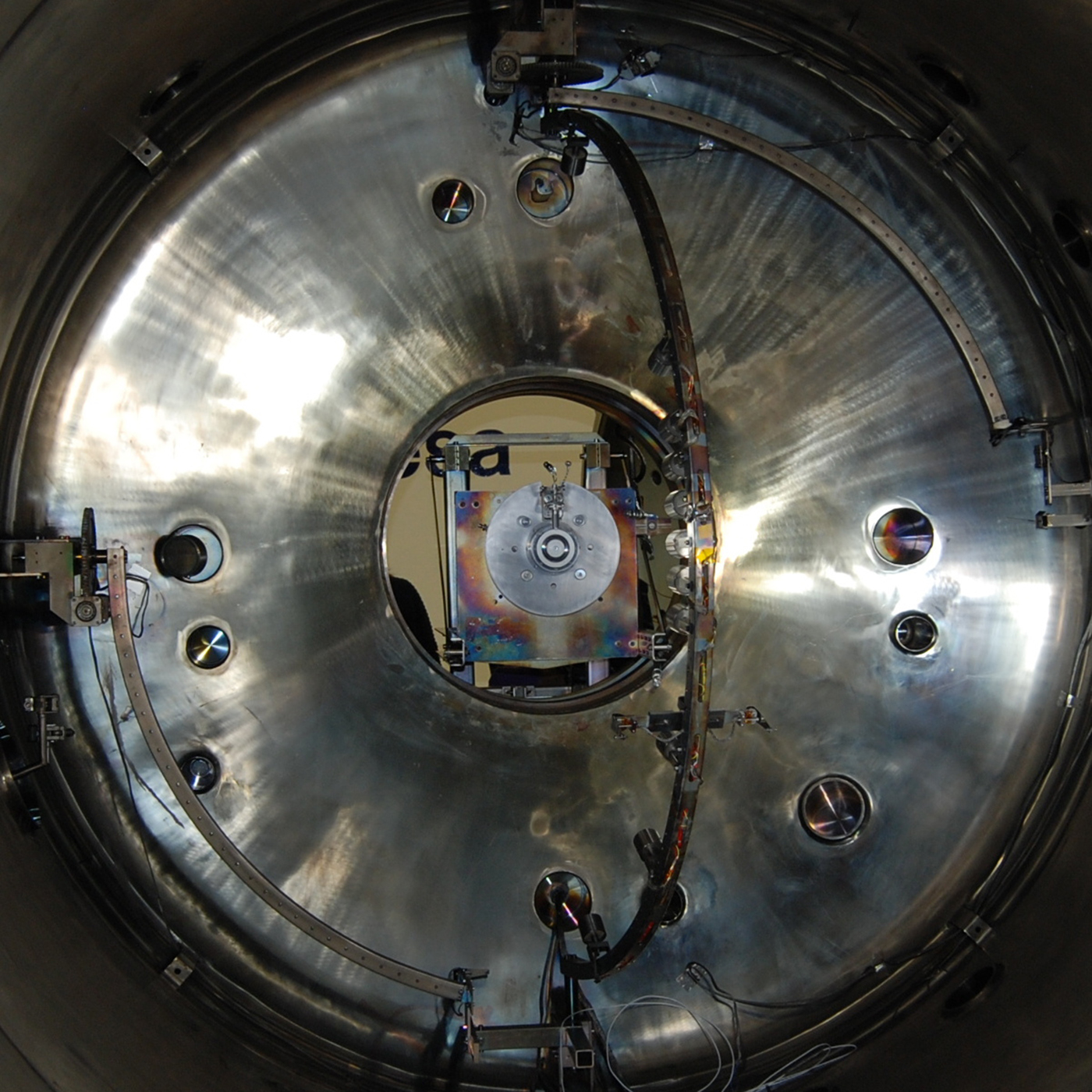
Fig. 2. Faraday probes in ESTEC laboratory.
Jet momentum losses due to beam divergence are expressed as a momentum-weighted average quantity from the formulation of thrust what is equal to the ratio of the measured thrust component directed along the thruster centerline relative to the theoretical thrust achieved when all ions are traveling parallel to the thruster centerline. Momentum losses associated with plume divergence may be calculated with knowledge of the total mass flow rate, measured thrust, and the mass-weighted average velocity. The momentum-weighted average divergence can be also approximated as the charge-weighted average divergence for an axisymmetric plume.
 $${\rm cos}{\rm \theta} _J^2 = \left( {\displaystyle{{2{\rm \pi} R^2 \int \nolimits^ J({\rm \theta} ){\rm cos}({\rm \theta} ){\rm sin}({\rm \theta} )d{\rm \theta}} \over {2{\rm \pi} R^2 \int \nolimits^ J({\rm \theta} ){\rm sin}({\rm \theta} )d{\rm \theta}}}} \right)^2.$$
Off-axis cosine losses integrated in the numerator of above equation quantify the axial component of beam current that generates thrust. Beam efficiency is evaluated as a charge-weighted average cosine, which is equal to the square of the axial component of ion beam current relative to the total ion beam current as measured by a Faraday probe (Brown, Reference Brown2009).
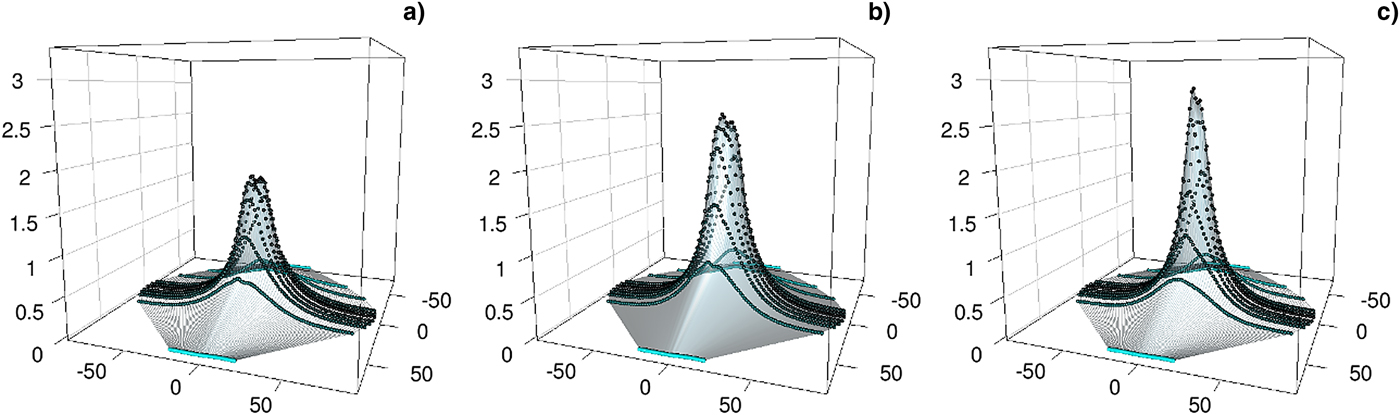
In order to characterize the beam, 3D and 2D profiles of ion charge flux were created. In Figure 3 are shown three profiles with the thruster working in different operating conditions. The 2D profiles from the main (central) Faraday probe with respect to the discharge voltage, magnetic field topography (controlled by coil currents), and mass flow rates from anode and cathode, as well as the corresponding angles of divergence are presented in Figure 4. The summary plots for all investigated cases are in Figure 5.

Fig. 3. The 3D profiles of ion charge flux for different operating conditions: (a) U d = 240 V, I inn = 5.0 A, I out = 2.5 A, m c = 1 sccm, m a = 1 mg/s; (b) U d = 260 V, I inn = 5.0 A, I out = 2.0 A, m c = 1 sccm, m a = 1.19 mg/s; (c) U d = 300 V, I inn = 5.0 A, I out = 2.0 A, m c = 3 sccm, m a = 1 mg/s.
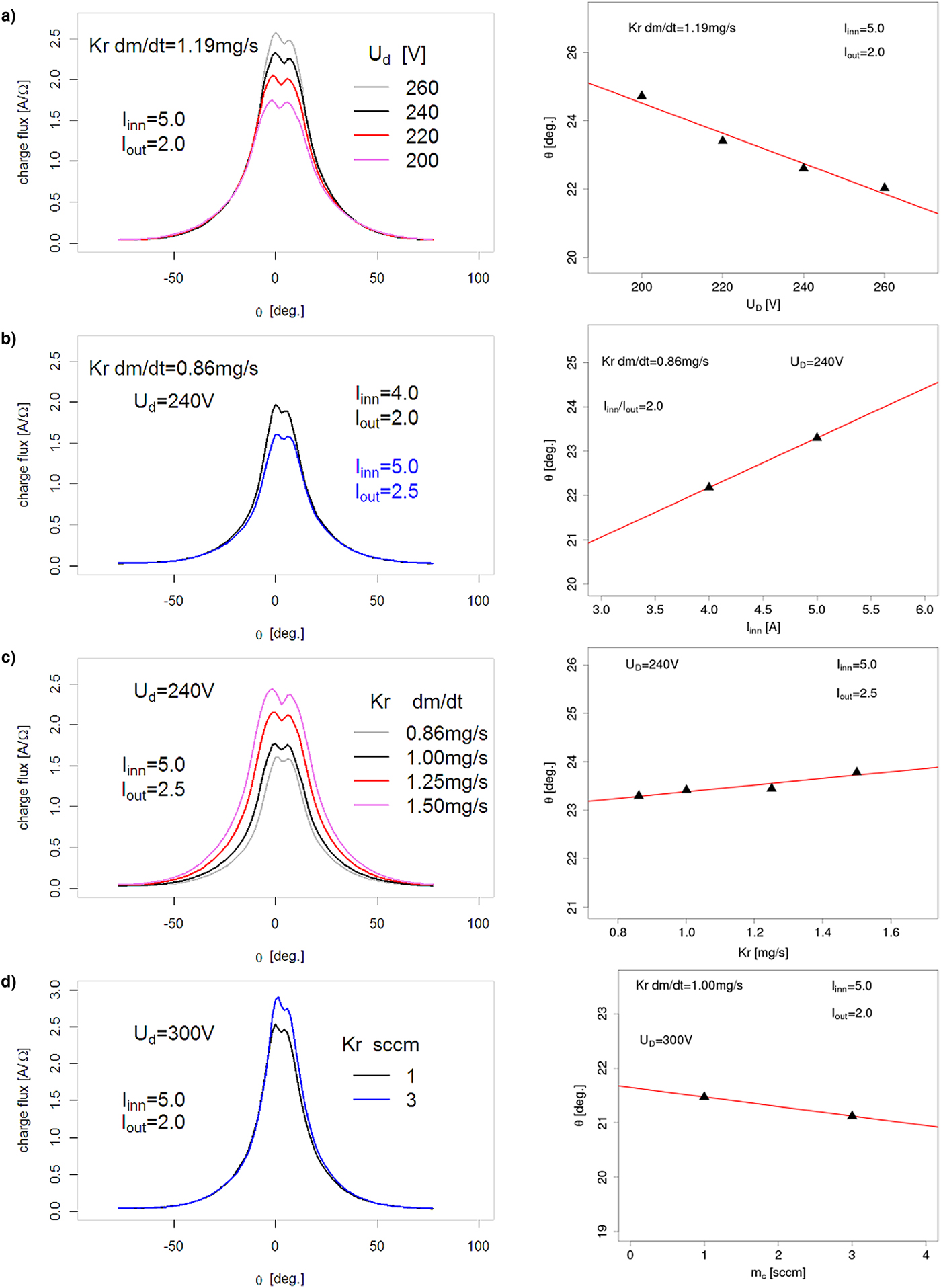
Fig. 4. The 2D profiles and divergence angles with respect to (a) discharge voltage, (b) coil currents, (c) anode mass flow rate, and (d) cathode mass flow rate.
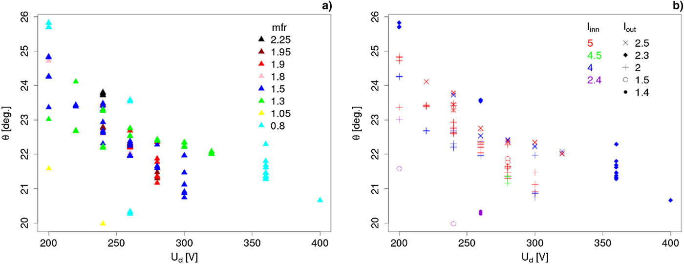
Fig. 5. Divergence angles for all investigated cases with respect to discharge voltage. Legends correspond to (a) mass flow rate and (b) coil currents.
The obtained results demonstrate that shape of the profile depends on all the controlled variables – applied voltage, magnetic field strength, and topography (controlled by coil currents) and gas mass flow rates. It was observed that beam divergence strongly decreases as the voltage applied increases for all cases. This is due to the fact that higher discharge voltage corresponds to higher axial electric field, thus larger axial velocities of the accelerated ions. Bigger ratio of axial to transverse ion velocities results in smaller divergence of the beam. It was noted that the magnetic field also strongly influences the shape of this beam, as it should. For the case presented, it seems that for the same field shape (coil currents ratio) smaller field magnitude lowers the beam divergence, although the amount of data is insufficient to draw any conclusions as to the general tendency. In addition, it was noted that the increased gas flow through the anode causes the beam to slowly expand, but also that the gas flow through the cathode causes minor differences in its appearance.
Langmuir probe
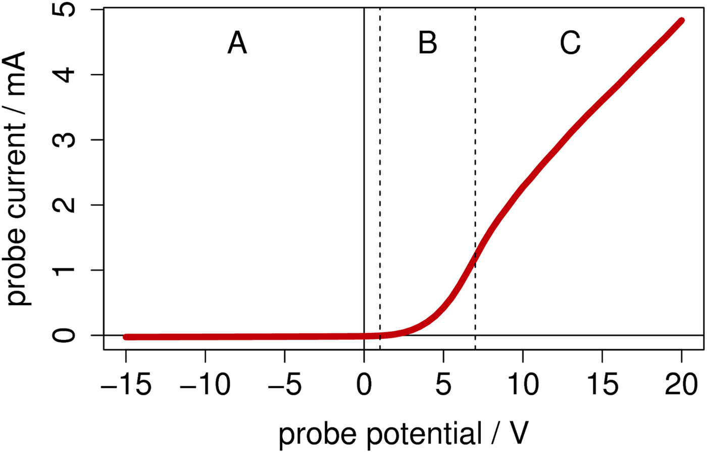
Langmuir probe is a small electrode, typically cylindrical, spherical, or planar in shape, inserted into plasma and polarized in wide range. Only the ions and electrons with energies sufficient to cross plasma sheath of the probe are collected and so current–voltage characteristics can be obtained (Fig. 6). Then, from the current–voltage (I–V) curves of the probe, several plasma parameters can be calculated.

Fig. 6. Example of Langmuir probe current–voltage characteristic for a cylindrical probe. (a) Ion saturation current, (b) transition region, (c) electron saturation current.
To measure some of the plasma parameters in the far-field plume of the Hall thruster, a single cylindrical Langmuir probe was manufactured in the IPPLM PlaNS laboratory (Fig. 7) together with a dedicated power supply unit. The electrode of the probe was made from 0.2 mm-thick tungsten wire with the collecting part 9.2 mm long. The probe was positioned in the thruster axis at a distance of approximately 470 mm from the channel exit and was aligned with the plasma flow, so the current to the probe resulted mainly from the thermal motion of the electrons and ions. The probe current–voltage characteristics were collected in the range of −60 to 30 V with the measured current signal averaged over 256 traces on an oscilloscope for each point.
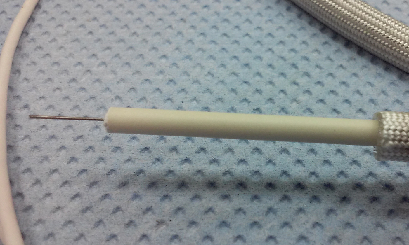
Fig. 7. Langmuir probe manufactured in the PlaNS laboratory.
Several different processing routines that provide for electron current separation (Steinbruchel, Reference Steinbruchel1990; Chen et al., Reference Chen, Evans and Arnush2002; Reference Chen2003; Raites et al., Reference Raites, Staack, Smirnov and Fisch2005; Merlino, Reference Merlino2007; Godyak and Alexandrovich, Reference Godyak and Alexandrovich2015), electron energy probability function reconstruction (Druyvesteyn, Reference Druyvesteyn1930; Godyak and Demidov, Reference Godyak and Demidov2011; Godyak and Alexandrovich, Reference Godyak and Alexandrovich2015), and plasma parameter calculation (Steinbruchel, Reference Steinbruchel1990; Chen et al., Reference Chen, Evans and Arnush2002; Reference Chen2003; Conde, Reference Conde2011; Godyak and Demidov, Reference Godyak and Demidov2011; Godyak and Alexandrovich, Reference Godyak and Alexandrovich2015) were examined. Using various methods of electron current separation, it was decided that a simple linear fit of ion current I i gave the best agreement with the experimental results and this method was used throughout the analysis. Plasma (space) potential was obtained as the point on I–V curve where a knee in exponential growth of electron current I e occurs [i.e., where I e’(V) = max]. Electron energy probability function was calculated with the Druyvesteyn method that uses the second derivative of the electron current, which was computed using approximating spline functions to avoid numerical noise. Because it was found that in our case I i was approximately linear with V, then I i” = 0 and I e” = I”. It was noted that the assumption about Maxwellian electron energy probability function  $(f_{\rm M}({\rm \varepsilon} ) \sim \sqrt {\rm \varepsilon} \; {\rm exp}( - {\rm \varepsilon} /a))$ that is made for most of the methods was not satisfied in our conditions, as seen in Figure 8. The obtained electron energy probability function resembles the so-called Druyvesteyn distribution
  $(f_{\rm D}({\rm \varepsilon} ) \sim \sqrt {\rm \varepsilon} \; {\rm exp}( - {\rm \varepsilon} ^2/b))$ that is reported to be related to the dominance of elastic collisions between electrons and neutrals in plasma, in which the energy transfer is not effective and electrons cannot thermalize (Godyak and Demidov, Reference Godyak and Demidov2011). Therefore, electron concentration and temperature were derived directly from the electron energy probability function (Godyak and Demidov, Reference Godyak and Demidov2011; Godyak and Alexandrovich, Reference Godyak and Alexandrovich2015) and not the classical Langmuir analysis.
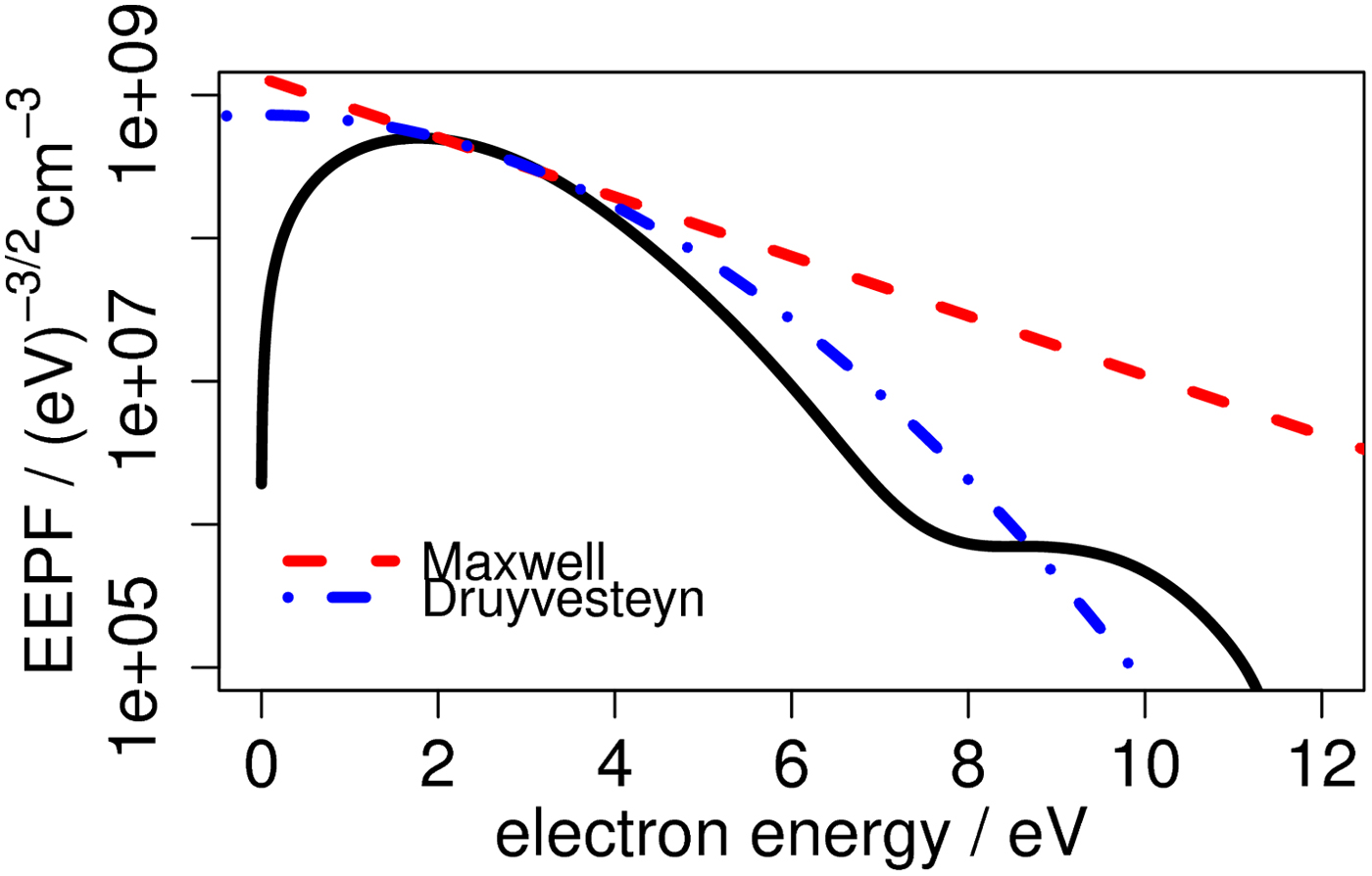
Fig. 8. Electron energy probability function with fitted Maxwell and Druyvesteyn distributions.
The resulted space potential V s, electron temperature T e, and electron concentration n e for some typical working conditions of KLIMT (discharge voltage 200–300 V, mass flow rate 1.00, 1.25 mg/s) for both gases (krypton and xenon) are shown in Figure 9. The magnetic field inside the discharge channel was adjusted with different values of coil currents to provide the most stable operation of the thruster, but was fixed throughout individual data series to allow for easier interpretation of the results.

Fig. 9. (a) Space potential V s, (b) electron temperature T e, and (c) electron concentration n e as a function of discharge voltage U d for different working conditions of KLIMT.
Obtained values of plasma parameters are comparable with plasma characteristics that were reported for thrusters of similar design (Dannenmayer et al., Reference Dannenmayer, Kudrna, Tichy and Mazzoufre2009; Lobbia and Gallimore, Reference Lobbia and Gallimore2010). Plasma space potential, electron temperature, and electron concentration all seem to rise with the discharge voltage. Higher electron temperatures for bigger voltages may be due to higher kinetic energies of the expelled ions, which grab the electrons from the cathode. Also, it was noted that for the same discharge voltages, krypton exhibits lower electron temperatures than xenon. The reason for this is not yet clear, but is believed to stem from the fact that xenon is over 1.5 times more massive, so the energy transfer between electrons and xenon ions is less effective than for krypton and the electrons cool slower. For the same reason, electron concentration is higher for krypton – for the same mass flow rate, there are much more krypton ions than xenon ions in the plasma. An increase in the electron concentration that was observed for increasing discharge voltage is consistent with the Faraday probe results in which the beam divergence is lower for higher voltages (Fig. 4). Moreover, for higher mass flow rates, the beam divergence increases so the net result on electron concentration may be either positive or negative, what was also observed.
Conclusions
All the obtained results, both from Faraday and Langmuir probes, seem to be consistent with our understanding of the Hall thruster plasma beam formation. In particular, it was observed that increasing of the discharge voltage results in less divergent beam and so higher electron concentration in the thruster axis. Additionally, higher ion energies obtained in this way produce higher plasma potentials and electron temperatures. Moreover, bigger mass flow rates do not result in much larger electron concentration because at the same time the beam divergence also grows.
Next step in the design of beam diagnostics for the PlaNS laboratory will be to prepare our own Faraday probe and produce a movable arm to allow for spatial measurements of the charge flux and plasma parameters. Additionally, an enhanced acquisition system for Langmuir probe will be manufactured to compensate stray effects not addressed in the first version (e.g., addition of chamber wall sheath in the probe circuit resistance) and make acquisition process more automatic to allow for higher number of data points to be taken.
Acknowledgments
Above results were presented on the Plasma 2017 conference in Warsaw organized by the Institute of Plasma Physics and Laser Microfusion. The studied 0.5 kW Hall thruster was developed in the scope of ESA/PECS Contract No. 4000107746/13/NL/KLM – Krypton Large IMpulse Thruster. Authors would like to thank Ms Kathe Dannenmayer, head of ESA Electric Propulsion laboratory in which part of the measurements was conducted, for her support.