


1. Introduction
Some small multiphase fluid containers may be blocked by liquid or gas. Fluid plugs occur in many processes, and may shut down the oxidizer flow in fuel cells (Zhang, Yang & Wang Reference Zhang, Yang and Wang2006), cause gas embolization in cardiovascular vessels (Lee, Wu & Li Reference Lee, Wu and Li2020), or degrade the transporting efficiency of the liquid propellant in fuel tanks of spacecraft under microgravity (Chen & Collicott Reference Chen and Collicott2006). It is of great importance to remove such fluid plugs by capillary emptying, which is capillary non-occluding and does not mean the tube would completely empty here.
Generally, the multiphase fluid interface deformation in a capillary can be affected considerably by a transverse body force (if the force exists). The critical Bond number is used as the critical parameter of determining the existence or non-existence of capillary plugs in a horizontal tube in a gravity field. The Bond number is given by
 \begin{equation}Bo = {\delta ^2}/l_{ca}^2,\end{equation}
where  $\delta $ is the characteristic length of the capillary tube with a cross-section of arbitrary geometry and
  ${l_{\textit{ca}}} = \sqrt {\sigma /\rho g} $ is the capillary length, with surface tension σ between liquid and gas, (positive) density difference ρ between liquid and gas and gravitational acceleration g. Generally, in a horizontal open or concentric annular capillary in a downward gravity field (Manning, Collicott & Finn Reference Manning, Collicott and Finn2011; Manning & Collicott Reference Manning and Collicott2015; Rascón, Parry & Aarts Reference Rascón, Parry and Aarts2016; Zhu, Zhou & Zhang Reference Zhu, Zhou and Zhang2020; Zhou et al. Reference Zhou, Zhang, Zhu, Tan and Fu2021), the criterion for the non-existence of capillary plugs is
 \begin{equation}Bo > B{o_c},\end{equation}
where Boc is the critical Bond number. In this case, the emptying of a capillary tube is dominated by the gravity effect. The characteristic lengths of capillaries corresponding to the critical Bond numbers during investigation of the problem are mainly of millimetre or micrometre (see Parry et al. Reference Parry, Rascón, Jamie and Aarts2012) sizes. From the theory in a transverse body force field (Manning et al. Reference Manning, Collicott and Finn2011; Manning & Collicott Reference Manning and Collicott2015; Rascón et al. Reference Rascón, Parry and Aarts2016; Zhu et al. Reference Zhu, Zhou and Zhang2020; Zhou et al. Reference Zhou, Zhang, Zhu, Tan and Fu2021) developed from the theory in microgravity (Concus & Finn Reference Concus and Finn1969; Finn Reference Finn1986), the critical Bond number can be obtained at a given contact angle.
New shapes of tubes for liquid non-occlusion in a transverse body force field have been investigated theoretically. A flattened ice-cream cone cylinder was designed by Manning et al. (Reference Manning, Collicott and Finn2011) for liquid non-occlusion. The critical Bond number for a rectangular tube was found to decrease when using a large enough width-to-height ratio of cross-section (Manning & Collicott Reference Manning and Collicott2015) and to further decrease when reducing the bottom contact angle and a side contact angle and increasing the top contact angle and the other side contact angle (Zhu et al. Reference Zhu, Zhou and Zhang2020). The critical Bond number was able to be changed by using other shapes (ellipse and triangle) and different orientations (Rascón et al. Reference Rascón, Parry and Aarts2016). For an existing small tube facing the problem of liquid plugs, how to remove the existing liquid plugs is of great importance. However, replacing a liquid-plugged tube by a new tube of a different shape having larger emptying capacity is a difficult process. Instead, a simple possible measure should be sought. In this situation, the idea of using an eccentrically positioned rod to avoid liquid plugs in zero gravity was proposed by Smedley (Reference Smedley1990) and Pour & Thiessen (Reference Pour and Thiessen2019); Zhou et al. (Reference Zhou, Zhang, Zhu, Tan and Fu2021) found that the insertion of a rod at the centre of a horizontal liquid-plugged tube in a downward gravity field may help to remove liquid plugs from the tube.
Little experimental work about fluid occlusion and emptying in a capillary tube has been conducted to date. Verma et al. (Reference Verma, Saraj, Yadav, Singh and Guo2020) conducted experimental research on the generalized emptying criteria for finite-length capillaries by taking the contact line pinning at the sharp edge into consideration, and their experiment properly validates the theoretical conclusion that a different bottom contact angle from the top contact angle can cause the critical Bond number to vary (Parry et al. Reference Parry, Rascón, Jamie and Aarts2012; Zhu et al. Reference Zhu, Zhou and Zhang2020). Zhou et al. (Reference Zhou, Zhang, Zhu, Tan and Fu2021) performed an experimental study to validate their theoretical finding that the insertion of a rod into a tube at its centre helps to remove liquid occlusion.
Special tube structure with a rod inserted into the tube at an eccentric position has applications in other fluidic systems (Smedley Reference Smedley1990; Carrasco-Teja et al. Reference Carrasco-Teja, Frigaard, Seymour and Storey2008; Nikitin, Wang & Chernyshenko Reference Nikitin, Wang and Chernyshenko2009; Choueiri & Tavoularis Reference Choueiri and Tavoularis2015; Pour & Thiessen Reference Pour and Thiessen2019; Renteria & Frigaard Reference Renteria and Frigaard2020; Lamarche-Gagnon & Tavoularis Reference Lamarche-Gagnon and Tavoularis2021). It is worth noting that fluid occlusion (in a liquid–gas system) even at zero Bond number can be prevented by the use of eccentricity of annular tube cross-section (Smedley Reference Smedley1990; Pour & Thiessen Reference Pour and Thiessen2019) due to the ‘wedge’ effect, i.e. the effect of wedge-shaped regions (Concus & Finn Reference Concus and Finn1969; Protiere, Duprat & Stone Reference Protiere, Duprat and Stone2013; Reyssat Reference Reyssat2015; Rascón et al. Reference Rascón, Parry and Aarts2016). Can the ‘wedge’ effect (produced by the eccentricity) together with the gravity effect help to remove (avoid) fluid occlusion from (in) a horizontal annular tube in a downward gravity field for a larger range of contact angles? How do different eccentric angles influence fluid non-occlusion? Is the conventional criterion (1.2) for the non-existence of capillary plugs still applicable? Answers to these interesting questions have not been reported to date.
In this paper, we take a horizontal tube structure with a rod inserted eccentrically into a circular tube as an example to answer the above questions. We extend the research of Zhou et al. (Reference Zhou, Zhang, Zhu, Tan and Fu2021) to the effect of eccentricity on the emptying conditions of a horizontal annular capillary, observe new phenomena that have not been reported in a horizontal open (Manning et al. Reference Manning, Collicott and Finn2011; Manning & Collicott Reference Manning and Collicott2015; Rascón et al. Reference Rascón, Parry and Aarts2016; Zhu et al. Reference Zhu, Zhou and Zhang2020) or concentric annular tube (Zhou et al. Reference Zhou, Zhang, Zhu, Tan and Fu2021) or in an eccentric annular tube in zero gravity (Smedley Reference Smedley1990; Pour & Thiessen Reference Pour and Thiessen2019) and find greater emptying capacity than in Zhou et al. (Reference Zhou, Zhang, Zhu, Tan and Fu2021) to a large extent. In § 2, the mathematical model for a tube with a general cross-section of irregular geometry (e.g. an eccentric annulus) is developed. In § 3, the eccentricity effect on the critical Bond numbers and the emptying mechanisms is theoretically investigated by changing the magnitude and direction of eccentricity, the inner-to-outer radius ratio and the contact angles on the inner rod wall and the outer tube wall, and the effect of non-equal inner and outer contact angles is also examined. In § 4, an experiment is done for validation of the mathematical model. In § 5, main conclusions are drawn.
2. Mathematical model
Figure 1 shows a schematic of a gas–liquid interface in a general cross-section of an infinitely long horizontal circular tube with a horizontal rod inserted into it at an eccentric position in a downward gravity field in Cartesian coordinates (x, y, z). In this paper, for the irregular geometry of tube cross-section, the outer tube centre O lies on the x axis, while the centroid of the annulus is not necessarily on the x axis. The radius ratio of the tube χ is defined as the ratio of the rod radius Ri to the radius of the outer tube Ro. The displacement d is non-dimensionalized by the characteristic length Ro to obtain the eccentricity as e = d/Ro. The Bond number of the eccentric annular tube is given by Bo = (Ro/lca)2. The annular gap between the tube and the inside rod is filled with liquid and gas two-phase immiscible fluids, both of which have very large fixed volumes.

Figure 1. Schematic of general cross-section of liquid partially filling a horizontal circular tube of radius Ro with a rod of radius Ri inserted into it at an eccentric position in a downward gravity field. The displacement d is defined as the distance of the rod centre O′ away from the outer tube centre O. The eccentric angle θ is measured counterclockwise, starting from the positive x axis. The gas–liquid interface  $\varGamma$ meets the inner and outer walls at contact points with inner and outer contact angles γi and γo. The annular gap has total area
  $\varOmega$ and total inner and outer perimeters
  ${\varSigma _i}$ and
  ${\varSigma_o}$, while the liquid has area
  ${\varOmega^\ast }$ and wetting inner and outer perimeters
  $\varSigma_i^\ast $ and
  $\varSigma_o^\ast $.
The three-dimensional (3-D) Young–Laplace equation due to gravity and the surface tension force can be expressed as (Finn Reference Finn1986)
 \begin{equation}\boldsymbol{\nabla }\boldsymbol{\cdot }\boldsymbol{T}u = l_{ca}^{ - 2}{y} + \lambda ,\quad \boldsymbol{T}u = \frac{{\boldsymbol{\nabla }u}}{{{{(1 + |\boldsymbol{\nabla }u{|^2})}^{0.5}}}},\end{equation}
where u(x, y) describes the shape of the 3-D liquid surface and λ is a Lagrange parameter. The following boundary conditions are satisfied:
 \begin{gather}\boldsymbol{\nu
}_{\boldsymbol{i}}\boldsymbol{\cdot }\boldsymbol{T}u =
\textrm{cos}\,{\gamma _i},\quad
\textrm{on}\;\textrm{the}\;\textrm{inner}\;\textrm{rod}\;\textrm{wall},\end{gather}
\begin{gather}\boldsymbol{\nu
}_{\boldsymbol{i}}\boldsymbol{\cdot }\boldsymbol{T}u =
\textrm{cos}\,{\gamma _i},\quad
\textrm{on}\;\textrm{the}\;\textrm{inner}\;\textrm{rod}\;\textrm{wall},\end{gather} \begin{gather}{\boldsymbol{\nu }_{\boldsymbol{o}}}\boldsymbol{\cdot }\boldsymbol{T}u = \textrm{cos}\,{\gamma _o},\quad \textrm{on}\;\textrm{the}\;\textrm{outer}\;\textrm{tube}\;\textrm{wall},\end{gather}
where  ${\boldsymbol{\nu }_{\boldsymbol{i}}}$ is the unit exterior normal to the tube on the inner perimeter
  ${\varSigma_i}$ of the annular cross-section,
  ${\boldsymbol{\nu }_{\boldsymbol{o}}}$ is the unit exterior normal to the tube on the outer perimeter
  ${\varSigma_o}$ and γi and γo are the inner and outer contact angles, respectively. According to the Green formula, the following term can be given based on (2.2a) and (2.2b):
 \begin{equation}\int_\varOmega {\textrm{div}\,\boldsymbol{T}u} = \int_{{\varSigma _i}} {\boldsymbol{v}\boldsymbol{\cdot }\boldsymbol{T}u} + \int_{{\varSigma _o}} {\boldsymbol{v}\boldsymbol{\cdot }\boldsymbol{T}u} = |{{\varSigma _i}} |\,\textrm{cos}\,{\gamma _i} + |{{\varSigma _o}} |\,\textrm{cos}\,{\gamma _o}.\end{equation}
The Lagrange multiplier λ is determined by the liquid volume and container, but is not related to the liquid volume for a capillary of a constant cross-section. By integration of (2.1a) and employing (2.3), one obtains
 \begin{align}\lambda = \frac{1}{{|\varOmega |}}\left( {\int_\varOmega {\textrm{div}\,\boldsymbol{T}u} - l_{ca}^{ - 2}\varUpsilon } \right) = \frac{1}{{|\varOmega |}}(|{\varSigma _i}|\,\textrm{cos}\,{\gamma _i} + |{\varSigma _o}|\,\textrm{cos}\,{\gamma _o} - l_{ca}^{ - 2}\varUpsilon ),\quad \varUpsilon = \int_\varOmega y .\end{align}
For a circular tube with a rod inserted at an eccentric position, λ is rewritten as
 \begin{equation}\lambda = \frac{{2({R_o}\,\textrm{cos}\,{\gamma _o} + {R_i}\,\textrm{cos}\,{\gamma _i}) + l_{ca}^{ - 2}{R_o}R_i^2e\,\textrm{sin}\,\theta }}{{R_o^2 - R_i^2}} = \frac{{2(\textrm{cos}\,{\gamma _o} + \chi \,\textrm{cos}\,{\gamma _i}) + l_{ca}^{ - 2}R_o^2{\chi ^2}e\,\textrm{sin}\,\theta }}{{{R_o}(1 - {\chi ^2})}},\end{equation}
where θ is the eccentric angle. For the concentricity case and the horizontal eccentricity case, the centroid of the annulus just lies on the x axis, and λ is reduced to (Zhou et al. Reference Zhou, Zhang, Zhu, Tan and Fu2021)
 \begin{equation}\varUpsilon = \int_\varOmega y = 0,\quad \lambda = \frac{{|{\varSigma _i}|\,\cos \,{\gamma _i} + |{\varSigma _o}|\,\cos \,{\gamma _o}}}{{|\varOmega |}} = \frac{{2(\textrm{cos}\,{\gamma _o} + \chi \,\textrm{cos}\,{\gamma _i})}}{{{R_o}(1 - {\chi ^2})}}.\end{equation}
If  ${\gamma _i} = {\gamma _o} = 90^\circ $, then (2.5) is reduced to
 \begin{equation}\lambda = \frac{{l_{ca}^{ - 2}{R_o}{\chi ^2}e\,\textrm{sin}\,\theta }}{{1 - {\chi ^2}}}.\end{equation}
Under the critical condition of transition between liquid plug and liquid non-occlusion (corresponding to the critical Bond number), the tongue of a large 3-D droplet can be seen to be infinitely long with its cross-section being translationally invariant. The total free energy of a 3-D droplet that contains the free surface energy, the wetting energy, the gravitational energy and a liquid internal energy term imposing a volumetric constraint on the problem is finite. Thus, the total free energy per unit length of the tongue corresponding to the critical Bond number should be equal to zero. On this occasion, the 3-D problem of determining the critical conditions of transition between liquid plug and liquid non-occlusion is reduced to an associated two-dimensional (2-D) problem. The functional denoting the total free energy of a drop per unit length of liquid tongue based on a general cross-section of an annular capillary is given by (Zhou et al. Reference Zhou, Zhang, Zhu, Tan and Fu2021)
 \begin{equation}\varPhi = |\varGamma |- (|\varSigma _o^\ast |\,\textrm{cos}\,{\gamma _o} + |\varSigma _i^\ast |\,\textrm{cos}\,{\gamma _i}) + l_{ca}^{ - 2}\int_{{\varOmega ^\ast }} {y\,\textrm{d}\kern0.06em x\,\textrm{d}y} + \lambda |{\varOmega ^\ast }|,\end{equation}
where  $\mathrm{\varGamma }$ is the arc length of the gas–liquid interface and the gas–liquid interface can be determined by the Young–Laplace equation in two dimensions (Bhatnagar & Finn Reference Bhatnagar and Finn2016; Zhou & Zhang Reference Zhou and Zhang2017):
 \begin{equation}\frac{\textrm{d}}{{\textrm{d}\kern0.06em x}}\frac{{{y_x}}}{{\sqrt {1 + y_x^2} }} = l_{ca}^{ - 2}y + \lambda \textrm{,}\end{equation}
where  ${y_x} = \textrm{d}y/\textrm{d}\kern0.06em x$, with the inner and outer contact angle conditions satisfied,
  ${\varOmega^\mathrm{\ast }}$ is the liquid interior area and
  $\varSigma_i^\ast $ and
  $\varSigma_o^\ast $ are the wetting inner and outer perimeters, respectively (see figure 1). The critical Bond number can be determined by solving the following equation (Finn Reference Finn1986; Manning et al. Reference Manning, Collicott and Finn2011; Rascón et al. Reference Rascón, Parry and Aarts2016; Zhou et al. Reference Zhou, Zhang, Zhu, Tan and Fu2021):
 \begin{equation}\varPhi = 0.\end{equation}
Table 1 gives the computational procedure for obtaining the critical Bond number(s) of an eccentric annular capillary with a given geometry for a set of inner and outer contact angles when the critical Bond number(s) exists. The total free energy of the droplet in a tube always reaches the minimum possible value and, accordingly, at the fourth step of the computational procedure in table 1, the interface with the minimum energy  ${\varPhi _{min}}$ is chosen among all the possible interfaces calculated from (2.9) satisfying the contact angle conditions at a given Bond number. The non-existence of a liquid plug for a Bond number can be determined by judging the sign (positive or negative) of the value of the minimum energy
  ${\varPhi _{min}}$. The case of
  ${\varPhi _{min}} < 0$ for a Bond number indicates non-existence of a liquid plug, while
  ${\varPhi _{min}} > 0$ for a Bond number permits an occluding liquid surface in the capillary tube (Manning et al. Reference Manning, Collicott and Finn2011).
Table 1. Computational procedure to obtain the critical Bond number(s) for a given capillary tube geometry and specified contact angles when the critical Bond number(s) exists.

For  ${\gamma _o} = {\gamma _i} = 90^\circ $, the Lagrange multiplier λ and the critical Bond number for the horizontal eccentricity case are analytically obtained as
 \begin{equation}\lambda = 0,\quad B{o_c} = \frac{3}{{{{(\chi + 0.5)}^2} + 0.75}},\end{equation}
which are the same as those for the concentricity case (Zhou et al. Reference Zhou, Zhang, Zhu, Tan and Fu2021).
3. Results and discussion
The inside rod may be located at arbitrary eccentric positions in various directions in a tube. For vertical upward and downward eccentricities, the gas–liquid interface is symmetric with respect to the vertical axis of symmetry but the centroid of the annulus has a vertical displacement from the centre of the outer tube O. While, for horizontal eccentricity, the centroid of the annulus is kept at the same height as the outer tube centre, but the interface is not symmetric with respect to the vertical axis of symmetry. For eccentricity in directions other than vertical and horizontal directions, the interface is not symmetric with respect to the vertical axis of symmetry and the centroid of the annulus deviates slantly from the outer tube centre. These lead to the complexity of computation and analysis regarding this problem. The vertical and horizontal eccentricities are considered as the basic forms of eccentricity in terms of studying the eccentricity effect. In the following sections, we initially analyse the cases of vertical and horizontal eccentricities and then analyse the cases of inclined eccentricity at different inclined angles under the conditions of equal inner and outer contact angles. The contact angle studied here ranges from 1° to 179° at intervals of 1° and a local refinement around each kink is conducted. The effect of radius ratio is also discussed. The cases of non-equal inner and outer contact angles are finally investigated.
3.1. Vertical eccentricity
Consider an annular tube of vertical upward eccentricity. The eccentricity is restricted to be in a range  $0 < e < 1 - \chi $, while the cases
  $e > 1 - \chi $ will be non-physical. The critical emptying lines (each being a plot of critical Bond number as a function of contact angle) of the annular tubes with three radius ratios χ = 0.1, 0.4 and 0.7 and different vertical upward eccentricities for equal inner and outer contact angles (γo = γi = γ) are shown in figure 2. Due to the vertical eccentricity, the critical emptying line is not yet symmetric about the vertical line γ = 90°. Interestingly, lower and upper critical emptying lines occur when the eccentricity or radius ratio is large enough. The two critical emptying lines start appearing at smaller eccentricity for larger radius ratio (for example,
  $e \ge 0.7$ for χ = 0.1,
  $e \ge 0.3$ for χ = 0.4 and
  $e \ge 0.05$ for χ = 0.7), as shown in figure 2(a–c). Parameters
  ${\it Bo}_{cl}$ and
  ${\it Bo}_{cu}$ are defined as the critical Bond numbers on the lower and upper critical emptying lines, respectively. The lower and upper critical emptying lines touch the horizontal line
  $Bo = 0$ at a smaller contact angle
  ${\gamma _{\textit{B}{\textit{o}_{cl}} = 0}}$ (e.g. point J in figure 2b) and a larger contact angle
  ${\gamma _{\textit{B}{\textit{o}_{cu}} = 0}}$ (e.g. point K in figure 2b), respectively, and may intersect at the contact angle
  ${\gamma _{\textit{B}{\textit{o}_{cl}} = \textit{B}{\textit{o}_{cu}} \ne 0}}$ (e.g. point I in figure 2b).

Figure 2. Critical Bond numbers of annular tubes with different vertical upward eccentricities for different radius ratios (a) χ = 0.1, (b) χ = 0.4 and (c) χ = 0.7 versus contact angle γo = γi = γ. The squares denote the representative points each corresponding to a cross-section of the part of the interface that extends to infinite length at the critical Bond number. In (b), the circles on the black thick line denote three key points at e = 0.4. Points I, J and K correspond to the intersection point of the lower and upper critical emptying lines (i.e. the lines IJ and IK), Bocl = 0 and Bocu = 0, respectively. In the right-hand part of (b), 3-D interfaces (an oblique view) computed by Surface Evolver (Brakke Reference Brakke1992) at γ = 30° for e = 0.4 for different Bond numbers correspond to the triangles denoting the points P 1, P 2, P 3, P 4 and P 5, respectively. For points P 1 and P 2, the upper tongue is longer than the lower tongue (the phenomenon for point P 2 does not seem apparent due to the oblique view, and accordingly a grey circle through the tip of the lower tongue denoting a cross-section of the outer tube is plotted to help understand the phenomenon for point P 2), while for points P 3, P 4 and P 5, the lower tongue is longer than the upper tongue.
Generally, there are two kinks of the critical emptying lines containing lower and upper lines for a not-so-large radius ratio (for example, e = 0.8 for χ = 0.1 and e = 0.4 and 0.5 for χ = 0.4), one of which is also the intersection point of the lower and upper critical emptying lines. Occurrence of the two kinks is attributed to the contact point jumps due to the transition among the three non-occluded liquid topologies represented by the cross-sections D–F in figure 2(a) or the cross-sections C–E in figure 2(b). However, there is one kink of the critical emptying lines containing lower and upper lines for a larger radius ratio (for example, only one kink existing at e = 0.2 or 0.25 for χ = 0.7), and the kink is just the intersection point of the lower and upper critical emptying lines, as shown in figure 2(c). The reduction of the number of kinks by one as compared to the general case of a not-so-large radius ratio is attributed to the non-existence of the non-occluded liquid topology with the interface only meeting the outer wall due to the larger radius ratio. Additionally, for some smaller eccentricities (for example, e = 0.7 for χ = 0.1, e = 0.3 for χ = 0.4 and e = 0.05, 0.1 and 0.15 for χ = 0.7), the two critical emptying lines do not interact, and this causes one kink to disappear.
The occurrence of lower and upper critical emptying lines is attributed to two solutions (two critical Bond numbers) of (2.10) obtained for each of the contact angles  ${\gamma _{B{o_{cl}} = B{o_{cu}} \ne 0}} < \gamma \le {\gamma _{B{o_{cl}} = 0}}$, corresponding to two critical Bond numbers (figure 3), which is different from only one solution (Boc) of (2.10) for the horizontal open (Manning et al. Reference Manning, Collicott and Finn2011; Manning & Collicott Reference Manning and Collicott2015; Rascón et al. Reference Rascón, Parry and Aarts2016; Zhu et al. Reference Zhu, Zhou and Zhang2020) or concentric annular (Zhou et al. Reference Zhou, Zhang, Zhu, Tan and Fu2021) capillary in a normal downward gravity field. Besides the two critical Bond numbers for
  ${\gamma _{B{o_{cl}} = B{o_{cu}} \ne 0}} < \gamma \le {\gamma _{B{o_{cl}} = 0}}$, there is only one Boc for
  ${\gamma _{B{o_{cl}} = 0}} < \gamma \le {\gamma _{B{o_{cu}} = 0}}$ in the contact angle range of the critical emptying lines. For a contact angle ranging between
  ${\gamma _{B{o_{cl}} = B{o_{cu}} \ne 0}}$ and
  ${\gamma _{B{o_{cl}} = 0}}$, a re-entrant liquid state transition (i.e. transition from liquid non-occlusion to liquid plug and transition from liquid plug to liquid non-occlusion) with the Bond number increasing from 0 to a large enough value is found. In this case, the criterion (1.2) for the non-existence of capillary plugs is obviously not applicable. For the cases of two critical emptying lines, whether in the two-Boc contact angle range or in the one-Boc contact angle range, capillary plugs do not exist when the following condition is satisfied:
 \begin{equation}Bo < B{o_{cl}}\quad \textrm{or}\quad Bo > B{o_{cu}}.\end{equation}
As shown in figure 2, if  $Bo < B{o_{cl}}$, then liquid non-occlusion with the new topology where the liquid is trapped in the narrow region of the horizontal tube will occur due to the ‘wedge’ effect. Regarding the state of capillary plugs, the 3-D interfaces directly computed via Surface Evolver (Brakke Reference Brakke1992) for different Bond numbers between the lower and upper critical emptying lines at a representative contact angle of the tube (χ = 0.4 and e = 0.4) are displayed in figure 2(b). When Bo is slightly above the lower critical emptying line, the upper tongue of the plugging liquid droplet is much longer than the lower tongue. When the lower critical Bond number is attained, the upper tongue can be seen to be infinitely long. Crossing the lower critical emptying line by decreasing Bo can lead to the transition from liquid plug to liquid non-occlusion. With Bo increasing, the lower tongue of the plugging liquid droplet gradually becomes longer, which is accompanied by shortening of the upper tongue. When Bo approaches the upper critical emptying line, the lower tongue is much longer than the upper tongue (figure 4). When the upper critical Bond number is attained, the lower tongue also can be seen to be infinitely long. Crossing the upper emptying line by increasing Bo can induce the transition from liquid plug to liquid non-occlusion. The co-occurrence of upper tongue receding and lower tongue advancing is attributed to the gradual increase of the gravity effect relative to the ‘wedge’ effect with the increase of Bo. As expected, if
  $Bo > B{o_{cu}}$, then liquid non-occlusion with the topology where the liquid is wrapped in the wide region will occur due to the larger gravity leading to disappearance of the ‘wedge’ effect in this case.

Figure 3. Minimum energy  ${\varPhi_{min}}$ (calculated at the fourth step of table 1) for an annular tube of vertical upward eccentricity (χ = 0.4 and e = 0.4) for (a) the cases γo = γi = γ < 90° and (b) the cases γo = γi = γ > 90° versus Bond number. Points C–E and I–K correspond to C–E and I–K, respectively, as presented in figure 2(b). The dot-dashed line denotes the straight line for
  ${\varPhi_{min}} = 0$. In (a), each dashed line (a discontinuous segment of the line of
  ${\varPhi_{min}}$) represents a jump due to the transition between different non-occluded liquid topologies corresponding to minimal total free energy.

Figure 4. Schematic of evolution of the 3-D interface (an oblique view) (a) as the Bond number gradually decreases (from left to right) and approaches the lower critical Bond number and (b) as the Bond number gradually increases (from left to right) and approaches the upper critical Bond number. Some representative 3-D interfaces computed using Surface Evolver (Brakke Reference Brakke1992) are integrated in a horizontal eccentric annular tube.
The contact angles of the lower critical emptying line are smaller than 90°. For the contact angle range  ${\gamma _{B{o_{cl}} = B{o_{cu}} \ne 0}} < \gamma < {\gamma _{B{o_{cl}} = 0}}$, a sufficiently small capillary has a sufficiently small Bond number smaller than Bocl except at the contact angles adjacent to the contact angle
  ${\gamma _{B{o_{cl}} = 0}}$ (e.g. point J in figure 2b), and in this case, the sufficiently small capillary can be of approximate liquid non-occlusion. If
  $\gamma > {\gamma _{B{o_{cu}} = 0}}$ or
  $ < {\gamma _{B{o_{cl}} = B{o_{cu}} \ne 0}}$, the capillary tube will be in a state of unconditional liquid non-occlusion, no matter what the size of the capillary tube cross-section. Generally, a sufficiently small horizontal capillary tube in a downward gravity field will be approximately or unconditionally liquid non-occluding for the contact angle range excluding
  ${\gamma _{B{o_{cl}} = 0}} \leq \gamma \leq {\gamma _{B{o_{cu}} = 0}}$. The total contact angle range
  $\Delta \gamma $ of approximate and unconditional liquid non-occlusions is defined as
 \begin{equation}\Delta \gamma = {\gamma _{B{o_{cl}} = 0}} + 180^\circ{-} {\gamma _{B{o_{cu}} = 0}}.\end{equation}
According to the results calculated using the model, the two contact angles of zero critical Bond number have the following relationship:
 \begin{equation}{\gamma _{B{o_{cl}} = 0}} = 180^\circ{-}{\gamma _{B{o_{cu}} = 0}}.\end{equation}
This relationship (3.3) also can be obtained from Appendix A. Substituting (3.3) into (3.2),  $\Delta \gamma $ is rewritten as
  $\Delta \gamma = 2{\gamma _{B{o_{cl}} = 0}}$. It is also found from figure 2 that the value of
  $\Delta \gamma $ can be increased by an increase of vertical eccentricity or radius ratio.
Here, we discuss the relationship between the critical Bond numbers for vertical downward eccentricity and those for vertical upward eccentricity. Under the condition of equal magnitude of eccentricity, the perimeter of the tube cross-section for vertical downward eccentricity and that for vertical upward eccentricity are symmetric with respect to the horizontal axis. In this case, from Appendix A, a gas–liquid interface for vertical downward eccentricity at a contact angle γ + = 180° – γ that is symmetric to a given interface for vertical upward eccentricity at a contact angle γ with respect to the horizontal axis can be found, and the critical Bond number(s) for the vertical downward eccentricity at contact angle γ + = 180° − γ is equal to that for the vertical upward eccentricity at contact angle γ, as shown in figure 5. Accordingly, an eccentric angle range from 0° to 90° is sufficient when studying the effect of eccentric angle in the following sections.

Figure 5. Critical Bond numbers of annular tubes with vertical upward (θ = 90°) and downward (θ = −90°) eccentricities e = 0.4 for representative radius ratio χ = 0.4 versus contact angle γo = γi = γ.
3.2. Horizontal eccentricity
Consider an annular tube of horizontal eccentricity. The critical emptying lines of annular tubes with different horizontal eccentricities and representative radius ratio χ = 0.4 for γo = γi = γ are shown in figure 6. The critical emptying line is symmetric about the vertical line γ = 90°, which can be obtained from Appendix A. With the eccentricity increasing, the critical emptying line gradually drops. However, the maximums for different horizontal eccentricities reached at γ = 90° are equal for a certain radius ratio and are reduced with the radius ratio increasing. These can be directly derived from (2.11b). Furthermore, the case of two critical emptying lines does not yet occur. This is attributed to the geometric feature that the centroid of the eccentric annulus lies on the x axis, which is the same as the case of a concentric annulus. As shown in the figure, the critical Bond number reaches zero at a contact angle for  $e \ge 0.3$, and the contact angle range for unconditional liquid non-occlusion regardless of Bond numbers increases with the horizontal eccentricity increasing. Note that a kink appears at
  $\gamma \approx 72.8^\circ $ for the case e = 0.5 due to the occurrence of contact point jump (see configurations B and C in figure 6).

Figure 6. Critical Bond numbers of annular tubes with different horizontal eccentricities for representative radius ratio χ = 0.4 versus contact angle γo = γi = γ. An enlarged view of the line segments around the left kink of the curve for e = 0.5 is shown. Contact angle refinement for e = 0.4 is conducted in order to avoid the appearance of false kinks.
3.3. Inclined eccentricity
After the discussion about the vertical and horizontal eccentricity effects, we want to know what the vertical–horizontal mixed eccentricity effect (i.e. the inclined eccentricity effect) is on the critical Bond number. We take an eccentric angle θ = 45° as an example to analyse the cases of inclined eccentricity (see figure 7a). As expected,  $\Delta \gamma $ increases with inclined eccentricity (at a fixed eccentric angle) or radius ratio increasing. Interestingly,
  $\Delta \gamma $ remains constant with θ changing from 0° to 90° at intervals of 22.5° (see figure 7b). This is attributed to the fact that the two contact angles
  ${\gamma _{\textit{B}{\textit{o}_{cl}} = 0}}$ and
  ${\gamma _{\textit{B}{\textit{o}_{cu}} = 0}}$ determining the value of
  $\Delta \gamma $ are obtained in zero gravity, in which all the cases are not related to the eccentric angle.

Figure 7. Critical Bond numbers of annular tubes with (a) different radius ratios and different eccentricities for eccentric angle θ = 45° and with (b) radius ratio χ = 0.4 and eccentricity e = 0.4 for different eccentric angles versus contact angle γo = γi = γ.
3.4. Phase diagram
From the above analysis, it is found that the states are affected by the magnitude and direction of eccentricity, the radius ratio and the contact angles. In order to demonstrate this problem more clearly, the boundaries among four states, i.e. non-physical state, unconditional liquid non-occlusion, one Boc at a contact angle (gravity-dominated emptying mechanism) and two Boc at a contact angle (gravity and ‘wedge’ emptying mechanisms), in a space (γ, e/(1 − χ)) for γo = γi = γ are plotted in figure 8. In this figure, the horizontal dashed line, above which is non-physical, is determined by e/(1 − χ) = 1, and the curves going though points J and K correspond to zero critical Bond number. The solutions (γ, e/(1 − χ)) for (2.10) at zero Bond number also can be determined theoretically based on the geometrical relationship (Pour & Thiessen, Reference Pour and Thiessen2019), which is discussed in Appendix B.

Figure 8. (a) Phase diagram in a space (γ, e/(1 − χ)) for different eccentric angles for χ = 0.4 and (b) boundary lines in the parameter space for vertical eccentricity θ = 90° and different radius ratios χ = 0.1, 0.4 and 0.7. Equal inner and outer contact angles are used: γo = γi = γ. In (a), boundaries among four states are presented for different eccentric angles. With the eccentric angle varies, the boundary line (dashed line) between the left unconditional liquid non-occlusion region and the two-Boc region changes, while the two boundary lines (solid lines) corresponding to zero critical Bond number do not change. Points I–K correspond to I–K, respectively, as presented in figure 2(b). The blue text annotation corresponds to the region between the blue dashed line and the solid line through point J, representing the two-Boc region in the parameter space for the case of vertical eccentricity θ = 90°. In (b), the dashed line corresponds to the case denoted by the solid line in the same colour.
The cases as shown in figure 8 are the cases of γi = γo. As shown in figure 8(a), in the parameter space (γ, e/(1 − χ)), the two boundary lines of the one-Boc region (i.e. the lines corresponding to zero critical Bond number) can be theoretically determined using the above solving method. The two-Boc cases and unconditional liquid non-occlusion cases may occur for e/(1 − χ) ranging between 0.3376 and 1, and they would not exist for e/(1 − χ) < 0.3376 representing small enough eccentricity and small enough radius ratio. The two boundary lines of the one-Boc region do not change with the direction of eccentricity. In contrast, the boundary line between the left unconditional liquid non-occlusion region and the two-Boc region cannot be described theoretically and gradually drops (the two-Boc region in the parameter space becomes smaller) with θ decreasing from 90° to 0°, and it coincides with the left boundary line of the one-Boc region when θ = 0°. This again illuminates that the two-Boc cases would not arise for horizontal eccentricity, as discussed in § 3.2. The two-Boc cases only occur at γ < 90° and the range of e/(1 − χ) corresponding to the cases becomes larger with γ decreasing.
As shown in figure 8(b), with the radius ratio increasing, the two-Boc region is enlarged, and the two boundary lines of the one-Boc region clearly drop, but the maximum value is kept constant at γ = 90°. The value of  $\Delta \gamma $ also increases largely. This implies that increasing the radius ratio can effectively enhance the possibility of liquid non-occlusion in a small enough eccentric annular capillary.
3.5. Non-equal inner and outer contact angles
The above analysis is based on γo = γi. The effect of  ${\gamma _o} \ne {\gamma _i}$ is examined in this section. The variation of the parameter e/(1 − χ) with γo, and the variation of
  $\Delta {\gamma _o}$ (defined as the outer contact angle range of approximate and unconditional liquid non-occlusions at a fixed value of γi) with e/(1 − χ) for different inner contact angles are compared with those for γo = γi (see figure 9). According to Appendix A, under zero gravity, for an eccentric annular tube, if the minimal energy
  $\phi_{min}$ at contact angles
  $\gamma_{o}$ and
  $\gamma_{i}$ is equal to 0, then
  $\varPhi^{+}_{min} = 0$ will exist at contact angles 180° − γo and
  $180^{\circ}-\gamma_{i}$. Accordingly, the boundary lines of the one-Boc region at contact angles γo and γi and those at contact angles 180° − γo and 180° − γi are symmetric with respect to the vertical line γo = 90°. The cases of γi > 90° have not been included in this analysis.

Figure 9. (a) Boundary lines in parameter space (γo, e/(1 − χ)) at χ = 0.4 and θ = 90° for different inner contact angles versus outer contact angle γo and (b) outer contact angle ranges of approximate and unconditional liquid non-occlusions Δγo for different inner contact angles versus e/(1 − χ). In (a), the dashed line corresponds to the case denoted by the solid line in the same colour.
The boundary lines of the one-Boc region for  ${\gamma _o} \ne {\gamma _i}$ are not symmetric about the vertical line γo = 90° except γi = 90°. With γi decreasing from 90° to 30°, the maximum gradually shifts to the right, which is accompanied by the reduction of the right unconditional liquid non-occlusion region, and the two-Boc region is enlarged (figure 9a). Moreover, the case γo = γi is found to have the maximum value of
  $\Delta {\gamma _o}$ (figure 9b). Accordingly, the condition of γo = γi is preferable in view of liquid non-occlusion in a small enough eccentric annular capillary.
4. Experimental validation
The mathematical model is developed to determine the critical emptying conditions for a tube with a cross-section of irregular geometry. By analysing the results calculated based on the developed mathematical model, the vertical eccentricity has a notable effect on preventing capillary plugs in a tube, and a new phenomenology about the existence of the re-entrant liquid state transition is found. We take a vertical eccentricity as an example to conduct experiments to validate the new phenomenology found theoretically.
The silica glass capillary tubes used for the experiments had a length of 20 cm and were open at both ends, and the silica glass rods had a length of 30 cm. The contact angles of water on the glass surfaces used were measured using the sessile drop method to be approximately 30°. Long capillary tubes and rods were used in order to make the effect of contact line pinning at the sharp edge at both ends become negligible when studying the eccentricity effect here. The eccentric annular tube was formed by hanging the inside rod on two accessories manufactured using 3-D printing technology. The tubes and rods were cleaned using an ultrasonic cleaning machine before the experiments. Deionized water and air were used as the liquid and the gas, respectively. The fluids in capillaries exposed to two LED light sources were visualized by employing a Nikon D7200 camera mounted with Nikon Micro-NIKKOR 105 mm f/2.8G macro lenses.
The lower and upper critical emptying lines theoretically calculated using this model for an eccentric annular capillary of radius ratio χ = 0.5 and vertical eccentricity e = 0.27 are displayed for experimental validation (see figure 10). The results of the experiments (radius ratio  $\chi \approx 0.5$ and vertical eccentricity
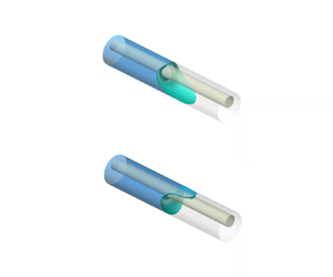
  $e \approx 0.27$) for five different Bond numbers are obtained using capillaries of different sizes and rods of different sizes. We observe from the experiments that the vertically eccentric annular tube is not plugged by liquid for both the Bond number below the lower critical emptying line and the Bond number above the upper critical emptying line, while it is liquid-occluded for Bond number between the lower and upper critical emptying lines. It is concluded that the experiments well validate the existence of the re-entrant liquid state transition found theoretically. In a horizontal tube without eccentricity, due to the gravity effect, a liquid plug is generally accompanied by a morphology in which the lower tongue of the liquid droplet is longer than the upper tongue (see the lower photograph in figure 3c in Zhou et al. (Reference Zhou, Zhang, Zhu, Tan and Fu2021)). In the experiments, when gravity is large enough (for example, the point denoted by a cross just above Q 2 in figure 10a), a liquid droplet morphology also exists with the lower tongue longer than the upper tongue similar to that in Zhou et al. (Reference Zhou, Zhang, Zhu, Tan and Fu2021). Additionally, we found experimentally that there is a case of liquid plugs where the upper tongue of the liquid droplet is a little longer than the lower tongue when Bo is a little above the lower critical emptying line (see Q 2 in figure 10b) because the ‘wedge’ effect gains an advantage over the gravity effect. This is in good agreement with the results directly computed via Surface Evolver (Brakke Reference Brakke1992) in 3-D mode.

Figure 10. (a) Theoretical predictions for lower and upper ‘critical emptying lines’ (Boc(γ), where γo = γi = γ) for a vertically eccentric annular capillary (χ = 0.5 and e = 0.27) and experimental results. The circles (e.g. Q 1 and Q 3) indicate liquid non-occlusion and the crosses (e.g. Q 2) indicate that the liquid plug remains. For the three experimental cases Q 1, Q 2 and Q 3, different diameters of outer tubes at 5.95, 7.96 and 12.11 mm and the corresponding different sizes of rods are used, respectively, thus leading to different Bond numbers. Note that, as predicted by theory, a small tube (see Q 1) and a large tube (see Q 3) become non-occluding after rod insertion whereas a medium-sized tube remains blocked (see Q 2). (b) Photographs of the liquid occlusion or non-occlusion for the three experimental cases Q 1, Q 2 and Q 3 representing the liquid states related to the re-entrant transition with increasing Bo. Note that the contact angles at the lower section of the tube in the picture of Q 2 seem much larger than 30°. This is attributed to the 3-D liquid surface (meniscus) concave towards the gas and the position of the camera relative to the horizontal capillary.
5. Conclusions
The effect of eccentricity of an annular capillary with a rod inserted into a circular tube in a normal gravity field on the critical Bond number is investigated theoretically and experimentally. The effects of horizontal eccentricity, vertical eccentricity and inclined eccentricity are analysed. A phase diagram in a parameter space (γ, e/(1 − χ)) at different eccentric angles for γo = γi is plotted. The influence of radius ratio and  ${\gamma _o} \ne {\gamma _i}$ is examined. The following conclusions are drawn from the above analysis.
For the non-horizontal eccentricity case, the lower and upper critical emptying lines arise when the eccentricity or the radius ratio is large enough, and the lower critical emptying line for γo = γi occurs at contact angles smaller than 90°. The critical Bond number(s) for the vertical upward eccentricity at a contact angle is equal to that for the vertical downward eccentricity at the supplementary contact angle. For the case of two critical Bond numbers at a contact angle, the re-entrant liquid state (liquid non-occlusion to plug to non-occlusion) transition occurs. For  $\textit{Bo} < \textit{B}{\textit{o}_{cl}}$, the tube is non-occluding due to the ‘wedge’ effect. For
  $\textit{B}{\textit{o}_{cl}} < \textit{Bo} < \textit{B}{\textit{o}_{cu}}$, the tube may be occluded by liquid and receding of the upper tongue and advancing of the lower tongue occur together with an increase of Bo. When the lower (upper) critical Bond number is attained, the upper (lower) tongue can be seen to be infinitely long. For
  $\textit{Bo} > \textit{Bo}_{cu}$, the tube is also non-occluding due to larger gravity.
Existence of the two critical emptying lines is accompanied by the occurrence of unconditional liquid non-occlusion in a certain contact angle range ( $\gamma > {\gamma _{\textit{B}{\textit{o}_{cu}} = 0}}$ and <
 ${\gamma _{B{o_{cl}} = B{o_{cu}} \ne 0}}$). A sufficiently small horizontal capillary tube will be approximately or unconditionally non-occluding if the contact angle is in the range
  $\Delta \gamma $ excluding those between the two contact angles at zero critical Bond number. In the parameter space (γ, e/(1 − χ)), with the eccentric angle increasing from 0° to 90°, the two-Boc region gradually becomes larger; however, the contact angle range
  $\Delta \gamma $ remains unchanged. The range
  $\Delta \gamma $ can be increased effectively by increasing the eccentricity and radius ratio. The case γo = γi is found to have the maximum value of
  $\Delta {\gamma _o}$ compared with different cases of
  ${\gamma _o} \ne {\gamma _i}$. The condition γo = γi is therefore preferable in view of liquid non-occlusion in a small enough eccentric annular capillary. This paper lays a solid foundation for more efficient use of inserting a rod into a horizontal capillary in terms of removing a liquid blockage, and for notably triggering the transition between a top flow path and a bottom flow path in optofluidic or microfluidic devices.
Funding
This research was supported in part by the National Natural Science Foundation of China (no. 11972170).
Declaration of interests
The authors report no conflict of interest.
Appendix A
Under the critical emptying conditions, for a horizontal tube having a general cross-section  $\varOmega$ in an arbitrary geometrical shape (figure 11), the gas–liquid interface
  $\varGamma$:
  $y = y(x)$ is described by the 2-D Young–Laplace equation (2.9) with the boundary conditions
  ${\boldsymbol{\nu }_{\boldsymbol{i}}}\boldsymbol{\cdot }\boldsymbol{T}y = \textrm{cos}\,{\gamma _i}$ and
  ${\boldsymbol{\nu }_{\boldsymbol{o}}}\boldsymbol{\cdot }\boldsymbol{T}y = \textrm{cos}\,{\gamma _o}$. If the perimeters
  $\varSigma _i^ +$ and
  $\varSigma _o^ +$ of cross-section
  ${\varOmega ^ + }$ of a horizontal tube are respectively symmetric to
  ${\varSigma_i}$ and
  ${\varSigma_o}$ for the horizontal tube with respect to the horizontal axis (figure 11),
  $\gamma _i^ + = 180^\circ{-} {\gamma _i}$ and
  $\gamma _o^ + = 180^\circ{-} {\gamma _o}$, under the condition of other properties the same, a curve
  ${\varGamma ^ + }:{y^ + } ={-} y(x)$ can be found, which satisfies the relationship
 \begin{equation}\frac{\textrm{d}}{{\textrm{d}\kern0.06em x}}\frac{{y_x^ + }}{{\sqrt {1 + {{(y_x^ + )}^2}} }} = l_{ca}^{ - 2}{y^ + } + {\lambda ^ + },\end{equation}
with the boundary conditions  ${\boldsymbol{\nu }_{\boldsymbol{i}}}\boldsymbol{\cdot }\boldsymbol{T}{y^ + } = \textrm{cos}\,\gamma _i^ + $ and
  ${\boldsymbol{\nu }_{\boldsymbol{o}}}\boldsymbol{\cdot }\boldsymbol{T}{y^ + } = \textrm{cos}\,\gamma _o^ + $. According to the above features, the following relationship can be held by
  ${\lambda ^ + } ={-} \lambda$,
  $|\varGamma |= |{{\varGamma ^ + }} |$,
  $|\varOmega |= |{{\varOmega ^ + }} |$,
  $|{{\varSigma _i}} |= |{\varSigma _i^ + } |$,
  $|{{\varSigma _o}} |= |{\varSigma _o^ + } |$,
  $|{{\varOmega ^\ast }} |= |{{\varOmega ^ + }} |- |{{\varOmega ^{ +{\ast} }}} |$,
  $|{\varSigma _i^\ast } |= |{\varSigma _i^ + } |- |{\varSigma {{_i^ + }^\ast }} |$ and
  $|{\varSigma _o^\ast } |= |{\varSigma _o^ + } |- |{\varSigma {{_o^ + }^\ast }} |$. In this case, the energy functional
  $\varPhi = {\varPhi ^ + }$. The critical Bond number(s) Boc(γi, γo) for the tube with
  $\varOmega$ is equal to Boc(180° − γi, 180° − γo) for the tube with
  ${\varOmega^ + }$.

Figure 11. Schematic of cross-section of a horizontal tube  $\varOmega$ in an arbitrary geometrical shape and the cross-section of another horizontal tube
  ${\varOmega^ + }$ whose perimeter is symmetric to the perimeter of the cross-section
  $\varOmega$ with respect to the horizontal axis.
It is concluded that the critical Bond number(s) for the vertical upward eccentricity at a contact angle is equal to the case of the vertical downward eccentricity having equal magnitude of the vertical upward eccentricity at the supplementary contact angle, which can also be demonstrated by the curves in the first and third graphs of figure 3 of Rascón et al. (Reference Rascón, Parry and Aarts2016).
Furthermore, for the horizontal eccentricity, the perimeter of the tube cross-section is symmetric with respect to the horizontal line of symmetry of the cross-section. Therefore, the critical emptying line is symmetric about the vertical line γo = γi = γ = 90°, which is demonstrated by the tubes each of which has one cross-section in another shape being symmetric with respect to the horizontal line of symmetry of the cross-section (Manning et al. Reference Manning, Collicott and Finn2011; Manning & Collicott Reference Manning and Collicott2015; Rascón et al. Reference Rascón, Parry and Aarts2016; Zhu et al. Reference Zhu, Zhou and Zhang2020; Zhou et al. Reference Zhou, Zhang, Zhu, Tan and Fu2021).
Under zero gravity, the shape of a liquid droplet in an eccentric annular tube is independent of the eccentric angle. In this case, the energy  $\varPhi$ for contact angles
  $\gamma_{i}$ and
  $\gamma_{o}$ and an interface
  $\varGamma $ for an eccentric annular tube is equal to the energy Φ + for
  $\gamma _i^ + = 180^\circ{-} {\gamma _i}$ and
  $\gamma _o^ + = 180^\circ{-} {\gamma _o}$, and
  $|{{\mathrm{\varGamma }^ + }} |= |\mathrm{\varGamma } |$ for the tube. If
  $\varPhi_{min} = 0$ at contact angles
  $\gamma_{i}$ and
  $\gamma_{o}$, then
  $\varPhi_{min}^+ = 0$ will exist at contact angles
  $180^{\circ}-\gamma_i$ and
  $180^{\circ}-\gamma_o$, for the tube. The contact angle corresponding to point J (figure 2b) is the supplementary contact angle corresponding to point K (figure 2b).
Appendix B
At zero Bond number, the energy functional (2.8) becomes
 \begin{equation}\varPhi = |\varGamma |- ({|{\varSigma _o^\ast } |\,\textrm{cos}\,{\gamma_o} + |{\varSigma _i^\ast } |\,\textrm{cos}\,{\gamma_i}} )+ \lambda |{{\varOmega ^\ast }} |,\end{equation}
where the Lagrange parameter λ is obtained from (2.5) as  $\lambda = {2(\textrm{cos}\,{\gamma _o} + \chi \,\textrm{cos}\,{\gamma _i})}/ {[{R_o}(1 - {\chi ^2})]}$, and the 2-D gas–liquid interface becomes a circular arc, the radius of which is given by
 \begin{equation}{R_s} = \frac{1}{\lambda } = \frac{{{R_o}(1 - {\chi ^2})}}{{2(\cos \,{\gamma _o} + \chi \,\textrm{cos}\,{\gamma _i})}}.\end{equation}
The interface is convex towards the liquid for Rs > 0 and concave towards the liquid for Rs < 0. The following analyses are suitable for Rs > 0 and Rs < 0. As gravity vanishes, the configuration of liquid in an eccentric annular cross-section is independent of the eccentric angle θ and symmetric with respect to the axis of symmetry (through the line OO′) of the cross-section.
The non-occluded liquid configurations for the cases under zero gravity can be divided into three types: the interface only meeting the outer wall, the interface only meeting the inner wall and the interface meeting the outer and inner walls. We found that the values of energy functional  $\varPhi $ for the former two types are always larger than 0. The two types will not be considered here for calculation of the critical parameters corresponding to zero Boc.
For the non-occluded liquid configuration with the interface meeting the outer and inner walls for a set of geometric parameters Ro, χ and e, and the contact angles γi and γo, the liquid may occupy the narrow part (figure 12a) or the wide part (figure 12b), and the location of the interface as shown in figure 12(a,b) can be determined by the geometrical relationship due to zero Bond number. The centre s of curvature of the interface segment on the right-hand side of the cross-section for each of the two cases as shown in figure 12(a,b) has coordinates  $({x_s},{y_s})$, where
  ${x_s}$ and
  ${{y}_{s}}$ are given by, respectively,
 \begin{gather}{x_s} = \sqrt {R_s^2 + R_o^2 - 2{R_s}{R_o}\,\textrm{cos}\,{\gamma _o}} \sin \left[ {{{\cos }^{ - 1}}\left( {\frac{{e{R_o}}}{{2\sqrt {R_s^2 + R_o^2 - 2{R_s}{R_o}\,\cos \,{\gamma_o}} }}} \right)} \right],\end{gather}
 \begin{gather}{y_s} = \frac{{e{R_o}}}{2}.\end{gather}
Figure 12. Non-occluded liquid configurations with the interface meeting the outer and inner walls at zero gravity for a set of inner and outer contact angles γi and γo. The liquid may occupy (a) the narrow part or (b) the wide part. In (a), α is the angular position of the outer contact point on the outer circle, β is the angular position of the inner contact point on the inner circle and  ${\varphi _{o}}$ and
  ${\varphi _i}$ are the angular positions of the outer and inner contact points on the interface arc, respectively. These angular positions are measured counterclockwise, starting from the positive x axis.
By considering the case that the liquid is wrapped in the narrow part (figure 12a), the angular position of the outer contact point on the outer circle, α, the angular position of the inner contact point on the inner circle, β, and the angular positions of the outer and inner contact points on the interface arc,  ${\varphi _{o}}$ and
  ${\varphi _i}$, are given by, respectively,
 \begin{gather}\alpha = \textrm{sgn}({R_s})\,\textrm{co}{\textrm{s}^{ - 1}}\left( {\frac{{{R_o} - {R_s}\,\textrm{cos}\,{\gamma_o}}}{{\sqrt {R_s^2 + R_o^2 - 2{R_s}{R_o}\,\textrm{cos}\,{\gamma_o}} }}} \right) + {\tan ^{ - 1}}\left( {\frac{{{y_s}}}{{{x_s}}}} \right), \end{gather}
 \begin{gather}\beta = \textrm{sgn}({R_s})\,\textrm{co}{\textrm{s}^{ - 1}}\left( {\frac{{\chi {R_o} + {R_s}\,\textrm{cos}\,{\gamma_i}}}{{\sqrt {R_s^2 + {{(\chi {R_o})}^2} + 2\chi {R_o}{R_s}\,\textrm{cos}\,{\gamma_i}} }}} \right) - {\tan ^{ - 1}}\left( {\frac{{{y_s}}}{{{x_s}}}} \right),\end{gather}
 \begin{gather}{\varphi _o} = \alpha + {\gamma _o},\quad {\varphi _i} = \beta + {\rm \pi}- {\gamma _i}.\end{gather}
Due to the symmetry of the cross-section, the lengths of the liquid boundary parameters  $\varGamma $,
  $\varSigma _o^\ast $ and
  $\varSigma _i^\ast $ can be expressed as
 \begin{equation}|\varGamma |= 2{R_s}({\varphi _i} - {\varphi _o}),\quad |{\varSigma _o^\ast } |= {R_o}({\rm \pi} - 2\alpha ),\quad |{\varSigma _i^\ast } |= \chi {R_o}({\rm \pi} - 2\beta ).\end{equation}
By the application of the Green formula, the liquid area becomes (Pour & Thiessen Reference Pour and Thiessen2019)
 \begin{align} |{{\varOmega ^\ast }} |& =R_o^2\left({\frac{{\rm \pi} }{2} - \alpha } \right) + \chi R_o^2\left( {\chi \beta - e\,\textrm{cos}\,\beta - \frac{{{\rm \pi} \chi }}{2}} \right) + R_s^2({\varphi _o} - {\varphi _i})\nonumber\\
&\quad + {R_s}[{x_s}(\textrm{sin}\,{\varphi _o} - \textrm{sin}\,{\varphi _i}) - {y_s}(\textrm{cos}\,{\varphi _o} - \textrm{cos}\,{\varphi _i})]. \end{align}
\begin{align} |{{\varOmega ^\ast }} |& =R_o^2\left({\frac{{\rm \pi} }{2} - \alpha } \right) + \chi R_o^2\left( {\chi \beta - e\,\textrm{cos}\,\beta - \frac{{{\rm \pi} \chi }}{2}} \right) + R_s^2({\varphi _o} - {\varphi _i})\nonumber\\
&\quad + {R_s}[{x_s}(\textrm{sin}\,{\varphi _o} - \textrm{sin}\,{\varphi _i}) - {y_s}(\textrm{cos}\,{\varphi _o} - \textrm{cos}\,{\varphi _i})]. \end{align}
Then, the value of energy functional for the case of liquid occupying the narrow part  ${\varPhi _n}$ can be calculated from (B1).
For the case of liquid wrapped in the wide part (figure 12b), the above equations (B4) and (B5) are not suitable due to the geometrical relationship. According to Appendix A, the energy functional for the case of liquid occupying the wide part  ${\varPhi _w}$ for a set of contact angles
  ${\gamma _i}$ and
  ${\gamma _o}$ will be equal to
  ${\varPhi _n}$ for another set of contact angles
  ${180^ \circ } - {\gamma _i}$ and
  ${180^ \circ } - {\gamma _o}$, which can be calculated using the above equations. Parameter
  ${\varPhi _{min}}$ is determined, which is equal to the minimum value of
  ${\varPhi _n}$ and
  ${\varPhi _w}$. One can repeat the above steps by changing the geometric parameters Ro, χ and e, and the contact angles γi and γo to find the critical parameters of geometry and contact angles corresponding to zero critical Bond number that lets
  ${\varPhi _{min}} = 0$.


