


Introduction
Pattern synthesis of uniform linear anti-interference arrays (ULAAs) is a traditional and classical topic, which has been extensively studied in the literature [Reference Khodier1–Reference Babakhani3]. Many synthesis methods have been proposed to achieve the radiation pattern performances with different requirements, such as the gain or directivity enhancement, sidelobe minimization, null controlling, and so on [Reference Van Luyen4–Reference Aslan6]. Among them, a particularly noteworthy application is to synthesize the radiation pattern with the sidelobe minimization and null controlling. In this type of method, the anti-interference function is realized by placing the nulls in the required directions of the interfering signals, and the radiation performance is improved by minimizing the peak sidelobe level (PSLL) while maintaining the main-beam gain. For the ULAAs design, the target can be achieved by optimizing the electrical parameters of each array element, e.g. the amplitude-only and phase-only. The design optimization of the ULAAs is demonstrated as a convenient way to search for the better array parameter arrangement [Reference Aslan6, Reference Almagboul7]. In the design optimization, it is important to determine an appropriate optimization algorithm for solving this problem efficiently.
In recent years, many research works are devoted to studying the optimization algorithms for pattern synthesis, which have been successfully used in the optimization design of the ULAAs [Reference Darvish8, Reference Patidar9]. The most often used optimization algorithm for solving the problems of the PSLL minimization and the null controlling is the evolutionary algorithm (EA). Based on the EAs' idea, many optimization algorithms are developed through improvement and modification of the classical EAs to overcome some of its limitations or increase the diversity of the searching way by means of the nature-inspired EAs (i.e. a type of optimization algorithms formed by imitating the evolution of the natural biological or social behavior). For example, classical EAs such as particle swarm optimization [Reference Khodier1], differential evolution algorithm [Reference Zhang10], simulated annealing algorithm [Reference Murino11] and genetic algorithm (GA) [Reference Tennant12, Reference Haupt13] have been used to minimize the PSLL and control the nulls at the specific positions. Among them, an improved GA based on the dynamic weight vector avoids the repeated calculation of the fitness function in each generation through a pre-computed discrete cosine transform matrix, which reduces the computational complexity of GA [Reference Yang14]. Besides, most of the research works focused on the nature-inspired EAs, such as ant lion algorithm [Reference Saxena15], invasive weed algorithm [Reference Karimkashi16], cat swarm algorithm [Reference Pappula17], biogeography-based optimization [Reference Singh18], whale optimization algorithm [Reference Zhang19], and so on, have also been developed. The advantage of this kind of algorithm lies in the relatively flexible searching way. However, the optimization process needs to execute a complex random search process and consider a large number of tuning parameters. Although the cuckoo search (CS) algorithm may have fewer parameters and simpler operations than other EAs [Reference Khodier20, Reference Khodier21], it still has the problem of slow convergence speed in the later stage of optimization. For the large-scale optimization problems with complex constraints, these kinds of methods require excessive analysis and iteration of optimization. To overcome this limitation, various improved methods were proposed to reduce the computational cost and increase the convergence speed [Reference Zhou22, Reference Chen23].
Gradient information is very important to determine the direction of iterative search in the optimization process. Gradient-based optimization algorithms (GOAs), such as MMA algorithm [Reference Svanberg24], SQP algorithm [Reference Boggs25], etc., are common algorithms that use the gradient information to accelerate the design optimization. The design optimization can be solved by a GOA more efficiently for the case when the sensitivities of the optimization are derived analytically [Reference Tortorelli26, Reference Liu27]. An optimization method based on the GOA was proposed to achieve the pattern synthesis by element rotation [Reference Wang28]. In this work, the radiation performance of low PSLL is considered and the sensitivity of the design objective with respect to the rotation angle of each array element is derived analytically. Then, the optimization problem is solved by the GOA, which improves the searching efficiency and saves the computation time. To simplify the analysis procedure, the array elements are generally assumed to be a series of identical currents, and the array patterns are characterized by the array factor. In this way, many SOAs are feasible to search for the global optimal solution without increasing the computational burden [Reference Pappula17–Reference Zhang19, Reference Khodier21]. However, it is generally believed that the mutual coupling affects the depth of nulls, and for some arrays, it also affects the position of nulls. To maintain the position of nulls precisely and calculate the radiation performance accurately, the full-wave method of moments (MoM) analysis is adopted to consider the mutual coupling of the array elements rigorously. Therefore, in the optimization procedure where the full-wave MoM simulations and the calculated sensitivities analytically are involved, the GOA is an effective choice to solve the optimization problem of the PSLL minimization and null controlling.
In this paper, a gradient-based optimization method for the PSLL minimization and null controlling of ULAAs is presented. In section “Optimization formulation and procedure”, the optimization formulation is given and the optimization procedure based on the GOA is proposed. The full-wave MoM is used to maintain the nulls and calculate the pattern performances accurately. The sensitivities of the design objective, the constraint function with respect to the different design variables (excitation amplitude or phase) are derived analytically. The optimization problem of the anti-interference array is solved by the GOA. In section “Numerical examples”, typical numerical examples are provided to verify the effectiveness of the proposed method. In section “Conclusion”, the advantage of the GOA is summarized and the conclusion is given.
Optimization formulation and procedure
The optimization formulation
The optimization problem of ULAAs for the interference suppression is defined as: maximize the main-beam gain and minimize the PSLL along with the constraints of null depth in the desired directions through optimizing the electrical parameters of each array element. The optimization problem can be formulated as:

where G m is the maximum of the gain in the main-beam direction. ${\boldsymbol G}_{{\rm SLL}}$ and ${\boldsymbol G}_{{\rm NULL}}$
 are the vectors of the gains within the sidelobe region and in the desired null directions, respectively. The design objective Φ0 is an explicit function that can describe a specific functional requirement, and evaluate the high-quality optimization solution. The constraint is defined to control the null depth by constraining the maximum gain value of the null depth ${\boldsymbol G}_{{\rm NULL}}$
 in all specified directions less than a given value G 0. Φ1 is defined as a constraint function to characterize the difference between the null depth constraint and G 0 in the optimization process. The constraint of null depth and Φ1 in the ULAAs optimization problem are expressed as:


where q is the operator that calculates the approximate maximum value, which is determined to be a sufficiently large positive integer. M 0 is the total number of nulls. G NULL,m represents the gain value of m-th null.
The optimization procedure
The GOA takes the advantage of the analytical properties of the optimization problem to improve the searching efficiency. In order to carry out the GOA to achieve the optimization design of coupled antenna arrays, it is necessary to establish the relationship among Φ0 and Φ1 (collectively referred to as Φk, k = 0 or 1) and ${\boldsymbol \chi }$ . This relationship requires that the change in Φk caused by the iteratively changed arrangements of array parameters can be accurately calculated. According to the relationships, the sensitivities of Φk and ${\boldsymbol \chi }$
 can be derived analytically. Then, the sensitivity information is introduced into the optimization procedure to speed up the convergence.
The computational steps for solving the optimization problem by the GOA are summarized as:
(1) The array parameter to be optimized is set as the design variable ${\boldsymbol \chi }$
 and the upper and lower bounds are limited to the range of $[ {{\boldsymbol \chi }_{{\rm min}}, \;{\boldsymbol \chi }_{{\rm max}}} ]$. Here, ${\boldsymbol \chi }$ represents the vector of the excitation amplitude or phase of each array element. In the design of ULAAs, the 2N symmetric geometric elements are assumed to be placed along the x-axis, as shown in Fig. 1. At the beginning of the optimization, a parameterized ULAAs model is generated from ${\boldsymbol \chi }$ and an initial arrangement of ${\boldsymbol \chi }_{{\rm ini}}$ is set up.
(2) Define Φk of the optimization problem. Φk can be calculated through an appropriate analysis method which requires the radiation pattern performances. The full-wave MoM is a common electromagnetic analysis method, and the radiation performance of the ULAAs can be accurately calculated by the full-wave MoM simulation. The following equation is formulated in matrix form as:
(3)$$\eqalign{& \left[{\matrix{ {\matrix{ {{\boldsymbol Z}_{11}} & \ldots & {{\boldsymbol Z}_{1j}} \cr \vdots & \ddots & \vdots \cr {{\boldsymbol Z}_{i1}} & \ldots & {{\boldsymbol Z}_{ij}} \cr } } & {\matrix{ \ldots & {{\boldsymbol Z}_{1N}} \cr \ddots & \vdots \cr \ldots & {{\boldsymbol Z}_{iN}} \cr } } \cr {\matrix{ \vdots & \ddots & \vdots \cr {{\boldsymbol Z}_{N1}} & \ldots & {{\boldsymbol Z}_{Nj}} \cr } } & {\matrix{ \ddots & \vdots \cr \ldots & {{\boldsymbol Z}_{NN}} \cr } } \cr } } \right]\left\{{\matrix{ {\matrix{ {{\boldsymbol J}_1} \cr \vdots \cr {{\boldsymbol J}_i} \cr } } \cr {\matrix{ \vdots \cr {{\boldsymbol J}_N} \cr } } \cr } } \right\} \cr & \quad = \left\{{\matrix{ {\matrix{ {{\boldsymbol V}_1( {\chi_1} ) } \cr \vdots \cr {{\boldsymbol V}_i( {\chi_i} ) } \cr } } \cr {\matrix{ \vdots \cr {{\boldsymbol V}_N( {\chi_N} ) } \cr } } \cr } } \right\}}$$where ${\boldsymbol Z}_{ij}$ represents the mutual impedance matrix between the i-th and j-th array element. ${\boldsymbol J}_i$ and ${\boldsymbol V}_i$ represent the unknown surface current and the incident field at the i-th element, respectively. The unknown currents ${\boldsymbol J}$ can be solved by assembling the ${\boldsymbol Z}$ and ${\boldsymbol V}$, and the gain of the radiation pattern G can be calculated by the equivalent dipole model [Reference Wang28]. The desired Φk can be obtained by the G m, ${\boldsymbol G}_{{\rm SLL}}$, and ${\boldsymbol G}_{{\rm NULL}}$, subsequently.(3) Calculate the sensitivities of Φk with respect to the ${\boldsymbol \chi }$
. Based on the parametric governing equation, the sensitivity of Φk with respect to ${\boldsymbol \chi }$ is derived as:(4)$$\displaystyle{{d{\rm \Phi }_k} \over {d{\boldsymbol \chi }}} = \displaystyle{{df( G ) } \over {dG}}\displaystyle{{dG} \over {d{\boldsymbol \chi }}}.$$The derivation of ∂f(G)/∂G depends on the specific Φ0 or Φ1. According to the chain rule, the sensitivity of G with respect to ${\boldsymbol \chi }$ is derived as:(5)$$\displaystyle{{dG} \over {d{\boldsymbol \chi }}} = \displaystyle{{\partial G} \over {\partial {\boldsymbol \chi }}} + \displaystyle{{\partial G} \over {\partial {\boldsymbol J}}}\displaystyle{{\partial {\boldsymbol J}} \over {\partial {\boldsymbol \chi }}}, \;$$where only ${\boldsymbol J}$ is an implicit function of ${\boldsymbol \chi }$, and it is difficult to manifest the function expression. Therefore, a complex adjoint vector $\;{\boldsymbol \lambda }$ is determined to eliminate the unknown $\partial {\boldsymbol J}/\partial {\boldsymbol \chi }$ by the adjoint method [Reference Tortorelli26]. The following derivation is given by:(6)$$\matrix{ {\displaystyle{{dG} \over {d{\boldsymbol \chi }}} = \displaystyle{{\partial G} \over {\partial {\boldsymbol \chi }}} + \displaystyle{{\partial G} \over {\partial {\boldsymbol J}}}\displaystyle{{\partial {\boldsymbol J}} \over {\partial {\boldsymbol \chi }}} + {\boldsymbol \lambda }^{\dagger} \displaystyle{{\partial [ {{\boldsymbol ZJ}-{\boldsymbol V}( {\boldsymbol \chi } ) } ] } \over {\partial {\boldsymbol \chi }}}\;\;\;\;\;\;\;\;\;\;\;\;\;\;\;\;\;\;\;\;\;\;\;\;\;\;\;\;\;\;\;\;\;} \cr { = \displaystyle{{\partial G} \over {\partial {\boldsymbol \chi }}} + \left({\displaystyle{{\partial G} \over {\partial {\boldsymbol J}}} + {\boldsymbol \lambda }^{\dagger} {\boldsymbol Z}} \right)\displaystyle{{\partial {\boldsymbol J}} \over {\partial {\boldsymbol \chi }}} + {\rm \Re }\left({{\boldsymbol \lambda }^{\dagger} \displaystyle{{\partial {\boldsymbol Z}} \over {\partial {\boldsymbol \chi }}}{\boldsymbol J}-{\boldsymbol \lambda }^{\dagger} \displaystyle{{\partial {\boldsymbol V}( {\boldsymbol \chi } ) } \over {\partial {\boldsymbol \chi }}}} \right), \;} \cr } $$where ${\rm \Re }$ is the real operator and ${\dagger}$ is the conjugated transpose operator. To complete the sensitivity analysis, the ${\boldsymbol \lambda }$ should satisfy the following equation:(7)$${\boldsymbol Z}^{\dagger} {\boldsymbol \lambda } = {-}\left({\displaystyle{{\partial G} \over {\partial {\boldsymbol J}}}} \right)^{\dagger} .$$Finally, the sensitivity analysis is completed and the formula (6) can be reduced to(8)$$\displaystyle{{dG} \over {d{\boldsymbol \chi }}} = {-}{\rm \Re }\left({{\boldsymbol \lambda }^{\dagger} \displaystyle{{\partial {\boldsymbol V}( {\boldsymbol \chi } ) } \over {\partial {\boldsymbol \chi }}}} \right).$$(4) Update the next generation of the ${\boldsymbol \chi }$
. It is noted that ${\boldsymbol V}( {\boldsymbol \chi } )$ should be automatically updated with ${\boldsymbol \chi }$ during the iteration process. Then, update Φk of the optimization problem and calculate their sensitivities. The optimization procedure needs to be evaluated based on the iteration of Φk and ${\boldsymbol \chi }$. If the convergence criterion or the maximum number of iterations is satisfied, the optimization will stop, otherwise, the optimization will go to (2).(5) Obtain the optimal solution ${\boldsymbol \chi }_{{\rm opt}}$
and synthesize the desired radiation pattern.


The flow chart of the GOA is illustrated in Fig. 2, where ζ is each iteration step in the optimization procedure and M is the maximum number of iterations. Tol is the calculation tolerance given based on the convergence criterion. According to the above optimization procedure, the optimization problem of the ULAAs can be solved efficiently.

Fig. 1. The geometry of 2N-elements symmetric ULAAs.
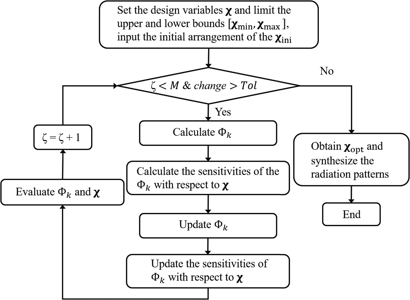
Fig. 2. The optimization flow chart of the GOA.
Numerical examples
In order to verify the effectiveness of the proposed method, typical numerical examples are provided to synthesize the radiation patterns of ULAAs. In Fig. 1, the design model consists of a series of dipoles with 0.04λ in width and 0.46λ in height, where λ is the wavelength of the simulation frequency. The distance between any two adjacent dipoles is 0.5λ. In the optimization design of the ULAAs, the main-beam has a width of $\vert \theta \vert \le 5^\circ$ in the direction of $\theta = 0^\circ$
 and $\varphi = 0^\circ$
 , where θ and φ denote the elevation and azimuth coordinates on the truncation boundary. The q and the G 0 are set to 10 and −45 dB, respectively. The proposed method uses the full-wave MoM to achieve the precise design and correct some existing optimization strategies that the mutual coupling was ignored or approximately considered. The full-wave MoM is utilized to calculate the antenna performances by considering the mutual coupling rigorously. The GOA is used to solve the optimization problem with the PSLL minimization and null controlling. Typical optimization algorithms, including the common GA and CS algorithm, are selected to solve the same optimization model and compared with the GOA in terms of the radiation pattern performance and computational time. Both GA and CS algorithm have a population size of 25. The maximum number of iterations in the three algorithms is 1000. The optimization is computed using a 3.60 GHz i7–7700K CPU and 8 GB RAM. In numerical examples, the number of array elements and the nulls are distinguished to illustrate the scalability of the proposed method.
Excitation amplitudes optimization
The first example is to optimize the excitation amplitudes of the 24-element ULAA with the double nulls at ${\pm} 30^\circ$ , ${\pm} 40^\circ$
 . Each dipole element is excited by a 1χ V voltage gap generator with 50 Ω characteristic impedance, where χ represents the excitation amplitude of each array element. ${\boldsymbol \chi }_{{\rm min}}$
 and ${\boldsymbol \chi }_{{\rm max}}$
 are set to 0 and 1, respectively. The initial arrangement ${\boldsymbol \chi }_{{\rm ini}}$
 is set to 0.5. The optimization information and the pattern properties obtained based on the three algorithms are shown in Table 1, which includes the maximum gain in the main-beam direction, the PSLL, the null positions, the iterations of optimization, and the CPU running time. Table 2 describes the design results of the excitation amplitudes optimization. The comparisons of the radiation pattern performances are calculated by the full-wave MoM analysis, which is illustrated in Fig. 3.

Fig. 3. The comparisons of the radiation pattern performances in the excitation amplitudes optimization.
Table 1. The information and pattern properties of the excitation amplitudes optimization

Table 2. The design result of the excitation amplitudes optimization

It is seen that GA and CS algorithms can provide the G m of 16.66 and 16.74 dB with a PSLL minimization of −2.79 and −3.59 dB, respectively. The CPU time of optimization is 210.1 and 315.8 min, respectively. The CS algorithm uses the MoM to analyze the radiation performances twice in each iteration for obtaining a good optimization result. The design results by the GOA can provide the G m of 16.74 dB with a PSLL minimization of −3.25 dB, and the CPU time of optimization is 10.6 min. It is illustrated that the proposed method reduces the CPU time of optimization compared with the GA and CS. The iterations of optimization based on the three algorithms may increase due to the null-depth constraint of multiple positions. All the design results maintain the nulls at the specific directions $( { \pm 30^\circ , \;\pm 40^\circ } )$ by the full-wave MoM analysis and satisfy the constraint of the nulls. By comparing the optimization information and the pattern properties, the amplitude-only optimization by the GOA can greatly shorten the computational time, and obtain nearly the same radiation pattern performance as the other two algorithms.
Excitation phases optimization
The second example is the 32-element ULAA with the null positions at ${\pm} 9^\circ$ and each dipole element is excited by a 1e jχ V voltage gap generator, where χ represents the excitation phase of each array element. It is determined to match with a 50 Ω transmission line. ${\boldsymbol \chi }_{{\rm min}}$
 and ${\boldsymbol \chi }_{{\rm max}}$
 are set to 0 and 2π, respectively, where ${\boldsymbol \chi }_{{\rm ini}}$
 is set to the middle value in the range of [0, 2π]. Table 3 shows the optimization information and the pattern properties based on the three algorithms, and Table 4 shows the design results of the excitation phases optimization. Figure 4 describes the comparisons of the radiation pattern performances. In the design optimization of the excitation phases, the constraints of null-depth are satisfied less than −45 dB. The design results are calculated by the full-wave MoM analysis for controlling the nulls at the specific directions $( { \pm 9^\circ } )$
 precisely and synthesizing the radiation patterns accurately. Compared with GA and CS algorithm, the results of the GOA provide the lowest PSLL, and the G m is higher than GA. The iterations and the computation time of optimization by the GOA are 232 and 9.9 min, respectively. This validates that solving the optimization problem of the ULAAs through the GOA can enhance the searching efficiency of the optimization efficiently and improve the radiation performances.

Fig. 4. The comparisons of the radiation pattern performances in the excitation phases optimization.
Table 3. The information and pattern properties of the excitation phases optimization

Table 4. The design result of the excitation phases optimization

Conclusion
This paper presents a gradient-based optimization method for the PSLL minimization and null controlling of linear arrays. The optimization procedure of the GOA is described, the optimization problem is defined and the optimization formulation is given. The sensitivities of the design objective, the constraint function with respect to the design variables are derived analytically. The full-wave MoM is used to consider the mutual coupling among the array elements rigorously. Typical numerical results show that, compared with the non-gradient GA and CS algorithm, the GOA can produce the desired null at the specific positions and minimize the PSLL, and greatly shorten the computation time. The proposed method contributes to synthesize the radiation pattern of coupled arrays efficiently and accurately. The results also validate its potential for solving the PSLL minimization and null controlling optimization problem with different numbers of radiating elements and nulls. In future work, we hope to apply the proposed method to practical examples to take advantage of considering the mutual coupling rigorously and solving the optimization problems efficiently.
Acknowledgements
This work was supported by the National Natural Science Foundation of China (Grant Nos: 11802050 and U1808215) and Shenzhen Science and Technology Research and Development Fund (JSGG20200102155001779). These financial supports are gratefully acknowledged.
 Renjing Gao received the M.S. and Ph.D. degrees in electronic engineering from Dalian University of Technology, Dalian, China, in 2002 and 2012, respectively. Since 1994, she has been with the Dalian University of Technology, where she is currently a Professor at the School of Automotive Engineering. She has performed research and published over 60 articles on a wide variety of design topics, including left-handed materials, mass sensors, digital control systems, and microelectromechanical systems. She holds more than 20 Chinese patents.
 Yi Tang received the B.S. and M.S. degrees in mechanical engineering from Yantai University, Yantai, China, in 2014 and 2017, respectively. He is currently pursuing the Ph.D. degree at the School of Automotive Engineering, Dalian University of Technology, Dalian, Liaoning, China. His major research fields include design optimization in electromagnetics, antennas, and phased arrays.
 Qi Wang received the B.S. and Ph.D. degrees in engineering mechanics from Dalian University of Technology, Dalian, Liaoning, China, in 2010 and 2017, respectively. Since 2017, he has been a Lecturer at the School of Automotive Engineering, Dalian University of Technology. His major research fields include design optimization in electromagnetics, topology optimization, antennas, arrays, sensors, and metamaterials.
 Shutian Liu received the B.S. and Ph.D. degrees in engineering mechanics from Dalian University of Technology, Dalian, Liaoning, China, in 1982 and 1994, respectively. He is currently a Professor at the State Key Laboratory of Structural Analysis for Industrial Equipment, Dalian University of Technology. He performed and published more than 200 articles. He holds more than 20 Chinese patents. His major research fields include structural and multidisciplinary optimization, computational mechanics, and metamaterial design.


