


1 Introduction
Interfacial phenomena lead to qualitatively different behaviours from those encountered in bulk materials. In fluid mechanics and soft matter, this includes in particular the existence of surface waves. As an example, water waves have fascinated a large number of physicists and mathematicians for many decades. Among them, Lagrange derived the equation of water waves (Darrigol Reference Darrigol2005), and Kelvin described the wake behind a ship (Kelvin 1887) – characterized by the universal angle of
 $19.7^{\circ }$
. This observation continues to trigger fundamental questions (Rabaud & Moisy Reference Rabaud and Moisy2013; Darmon, Benzaquen & Raphaël Reference Darmon, Benzaquen and Raphaël2014). Moreover, in the context of atomic-force microscopy and thin viscous films, the surface wake might directly be used as a new kind of nanorheological probe (Alleborn, Sharma & Delgado Reference Alleborn, Sharma and Delgado2007; Wedolowski & Napiórkowski Reference Wedolowski and Napiórkowski2015; Ledesma-Alonso et al.
Reference Ledesma-Alonso, Benzaquen, Salez and Raphaël2016). It may, as well, play a crucial role in biolocomotion, as demonstrated by the case of water striders that propel themselves using surface waves (Hu, Chan & Bush Reference Hu, Chan and Bush2003). For all the phenomena introduced above, and in fact many more (Démery & Dean Reference Démery and Dean2010), the disturbance creates waves and thus radiates energy. As a consequence, the operator experiences a force opposing its motion, called the wave resistance (Havelock Reference Havelock1932; Raphaël & De Gennes Reference Raphaël and De Gennes1996). This aspect is crucial in the naval industry, through optimal design of boat shapes and recycling of the radiated energy for ecological purposes.
$19.7^{\circ }$
. This observation continues to trigger fundamental questions (Rabaud & Moisy Reference Rabaud and Moisy2013; Darmon, Benzaquen & Raphaël Reference Darmon, Benzaquen and Raphaël2014). Moreover, in the context of atomic-force microscopy and thin viscous films, the surface wake might directly be used as a new kind of nanorheological probe (Alleborn, Sharma & Delgado Reference Alleborn, Sharma and Delgado2007; Wedolowski & Napiórkowski Reference Wedolowski and Napiórkowski2015; Ledesma-Alonso et al.
Reference Ledesma-Alonso, Benzaquen, Salez and Raphaël2016). It may, as well, play a crucial role in biolocomotion, as demonstrated by the case of water striders that propel themselves using surface waves (Hu, Chan & Bush Reference Hu, Chan and Bush2003). For all the phenomena introduced above, and in fact many more (Démery & Dean Reference Démery and Dean2010), the disturbance creates waves and thus radiates energy. As a consequence, the operator experiences a force opposing its motion, called the wave resistance (Havelock Reference Havelock1932; Raphaël & De Gennes Reference Raphaël and De Gennes1996). This aspect is crucial in the naval industry, through optimal design of boat shapes and recycling of the radiated energy for ecological purposes.
When a thin viscous film is coupled to an elastic layer, several interesting phenomena may happen. Classical hydrodynamic results have been revisited in this perspective, such as the capillary rise (Duprat, Aristoff & Stone Reference Duprat, Aristoff and Stone2011) and the Saffman–Taylor viscous fingering (Pihler-Puzović et al. Reference Pihler-Puzović, Illien, Heil and Juel2012; Al-Housseiny, Christov & Stone Reference Al-Housseiny, Christov and Stone2013; Stone & Duprat Reference Stone and Duprat2015), for which the added compliance can prevent the instability. Exploring the physics of painting, the propagation of the peeling front in a plastic sheet atop a glycerine layer has been studied (Hosoi & Mahadevan Reference Hosoi and Mahadevan2004), as well as the flexible scraping of viscous fluids (Seiwert, Quéré & Clanet Reference Seiwert, Quéré and Clanet2013). Besides, an emergent lift force exerted on a moving object near a brush (Sekimoto & Leibler Reference Sekimoto and Leibler1993), a soft boundary (Skotheim & Mahadevan Reference Skotheim and Mahadevan2004; Snoeijer, Eggers & Venner Reference Snoeijer, Eggers and Venner2013; Salez & Mahadevan Reference Salez and Mahadevan2015) or viscoelastic boundary (Pandey et al. Reference Pandey, Karpitschka, Venner and Snoeijer2016) was predicted and confirmed experimentally (Saintyves et al. Reference Saintyves, Jules, Salez and Mahadevan2016). Adhesive contact between a wet elastic sheet and a substrate also appears in a lot of physical and biological applications, and was shown to lead to patterns reminiscent of classical dewetting (Carlson, Mandre & Mahadevan Reference Carlson, Mandre and Mahadevan2015; Carlson & Mahadevan Reference Carlson and Mahadevan2016). Measurements on small-scale systems using surface-force apparatus revealed striking substrate deformations (Villey et al. Reference Villey, Martinot, Cottin-Bizonne, Phaner-Goutorbe, Léger, Restagno and Charlaix2013), with obvious implications on the accuracy of nanorheological experiments. Finally, Brownian motion may be impacted as well by the inclusion of soft boundaries (Daddi-Moussa-Ider, Guckenberger & Gekle Reference Daddi-Moussa-Ider, Guckenberger and Gekle2016).
The combination of both the wake and elastohydrodynamic physics introduced above naturally leads to a new class of interesting problems (Blyth, Părău & Vanden-Broeck Reference Blyth, Părău and Vanden-Broeck2011; Guyenne & Părău Reference Guyenne and Părău2014), with a broad range of applications in geophysics, biophysics, wave propagation and engineering. For instance, seminal studies on elastohydrodynamic wakes were motivated by the waves generated by landing planes in Antarctica (Părău & Dias Reference Părău and Dias2002; Părău & Vanden-Broeck Reference Părău and Vanden-Broeck2011). We note that the inertia of the fluid is a dominant ingredient in these works.
In the present article, we study the displacement of an external pressure field above a thin elastic sheet covering a narrow viscous film. In the lubrication approximation, we compute the elastohydrodynamic waves and wake, as well as the wave resistance, as a continuation of our previous work on the viscocapillary case (Ledesma-Alonso et al. Reference Ledesma-Alonso, Benzaquen, Salez and Raphaël2016). An equivalent of the Bond number where elasticity replaces capillarity – hereafter called the elastic Bond number – appears to be a central dimensionless parameter of the problem. The elastohydrodynamic wake is plotted for a large range of speeds and elastic Bond numbers. Finally, in the low-speed and high-speed regimes, we provide analytical asymptotic results for the wave resistance.
2 Elastohydrodynamic lubrication model
Let us consider a thin viscous film of thickness
 $h_{0}$
placed over a flat horizontal substrate, and covered by a thin elastic sheet of constant thickness
$h_{0}$
placed over a flat horizontal substrate, and covered by a thin elastic sheet of constant thickness
 $d\ll h_{0}$
. As depicted in figure 1, an external pressure field
$d\ll h_{0}$
. As depicted in figure 1, an external pressure field
 $\unicode[STIX]{x1D713}_{ext}(x-vt,y)$
, moving along the horizontal direction
$\unicode[STIX]{x1D713}_{ext}(x-vt,y)$
, moving along the horizontal direction
 $x$
at time
$x$
at time
 $t$
with a constant speed
$t$
with a constant speed
 $v\geqslant 0$
, is applied on the elastic sheet. A resulting non-constant profile
$v\geqslant 0$
, is applied on the elastic sheet. A resulting non-constant profile
 $h(x,y,t)$
of the liquid–elastic interface, with respect to the substrate, is created. We note that the total two-layer profile
$h(x,y,t)$
of the liquid–elastic interface, with respect to the substrate, is created. We note that the total two-layer profile
 $h+d$
has the same spatiotemporal variations as
$h+d$
has the same spatiotemporal variations as
 $h$
, and we thus focus on the latter only – with no loss of generality.
$h$
, and we thus focus on the latter only – with no loss of generality.

Figure 1. Schematic of the elastohydrodynamic wake. The top elastic film reacts to an external disturbance
 $\unicode[STIX]{x1D713}_{ext}(x-vt,y)$
moving at constant speed
$\unicode[STIX]{x1D713}_{ext}(x-vt,y)$
moving at constant speed
 $v\geqslant 0$
along the
$v\geqslant 0$
along the
 $x$
direction at time
$x$
direction at time
 $t$
.
$t$
.
Invoking the incompressible Stokes equation and volume conservation, and considering no slip at both the substrate–liquid and the liquid–elastic interfaces, the following equation is yielded in the lubrication approximation (Al-Housseiny et al. Reference Al-Housseiny, Christov and Stone2013; Lister, Peng & Neufeld Reference Lister, Peng and Neufeld2013; Carlson et al. Reference Carlson, Mandre and Mahadevan2015; Carlson & Mahadevan Reference Carlson and Mahadevan2016):
 $$\begin{eqnarray}\displaystyle {\displaystyle \frac{\unicode[STIX]{x2202}h}{\unicode[STIX]{x2202}t}}={\displaystyle \frac{1}{12\unicode[STIX]{x1D707}}}\unicode[STIX]{x1D735}\boldsymbol{\cdot }(h^{3}\unicode[STIX]{x1D735}P_{tot}). & & \displaystyle\end{eqnarray}$$
Here
 $\unicode[STIX]{x1D707}$
is the dynamic viscosity,
$\unicode[STIX]{x1D707}$
is the dynamic viscosity,
 $\unicode[STIX]{x1D735}$
is the gradient operator in two-dimensional (2D) Cartesian coordinates and
$\unicode[STIX]{x1D735}$
is the gradient operator in two-dimensional (2D) Cartesian coordinates and
 $P_{tot}(x,y,t)$
is the total pressure in the liquid. The last is given by the addition of the bending stress, the hydrostatic pressure and the external moving pressure field, and thus reads
$P_{tot}(x,y,t)$
is the total pressure in the liquid. The last is given by the addition of the bending stress, the hydrostatic pressure and the external moving pressure field, and thus reads
 $$\begin{eqnarray}\displaystyle P_{tot}=B\unicode[STIX]{x1D6FB}^{4}h+\unicode[STIX]{x1D70C}gh+\unicode[STIX]{x1D713}_{ext}, & & \displaystyle\end{eqnarray}$$
where
 $B=Ed^{3}/[12(1-\unicode[STIX]{x1D708}^{2})]$
is the bending stiffness,
$B=Ed^{3}/[12(1-\unicode[STIX]{x1D708}^{2})]$
is the bending stiffness,
 $E$
and
$E$
and
 $\unicode[STIX]{x1D708}$
are respectively the Young’s modulus and Poisson’s ratio (Landau & Lifshitz Reference Landau and Lifshitz1959),
$\unicode[STIX]{x1D708}$
are respectively the Young’s modulus and Poisson’s ratio (Landau & Lifshitz Reference Landau and Lifshitz1959),
 $g$
is the acceleration of gravity, and
$g$
is the acceleration of gravity, and
 $\unicode[STIX]{x1D70C}$
is the density of the liquid. Note that we assumed the bending stresses to be dominant over the stretching ones.
$\unicode[STIX]{x1D70C}$
is the density of the liquid. Note that we assumed the bending stresses to be dominant over the stretching ones.
Taking
 $h_{0}$
and the gravito-elastic length
$h_{0}$
and the gravito-elastic length
 $\unicode[STIX]{x1D705}_{el}^{-1}=[B/(\unicode[STIX]{x1D70C}g)]^{1/4}$
as the characteristic length scales in the vertical
$\unicode[STIX]{x1D705}_{el}^{-1}=[B/(\unicode[STIX]{x1D70C}g)]^{1/4}$
as the characteristic length scales in the vertical
 $z$
-direction and in the
$z$
-direction and in the
 $xy$
-plane, respectively, the time
$xy$
-plane, respectively, the time
 $\unicode[STIX]{x1D70F}=12\unicode[STIX]{x1D707}/(\unicode[STIX]{x1D70C}g\unicode[STIX]{x1D705}_{el}^{2}h_{0}^{3})$
as the characteristic time scale and
$\unicode[STIX]{x1D70F}=12\unicode[STIX]{x1D707}/(\unicode[STIX]{x1D70C}g\unicode[STIX]{x1D705}_{el}^{2}h_{0}^{3})$
as the characteristic time scale and
 $P_{ext}=\unicode[STIX]{x1D705}_{el}^{2}\iint \text{d}x\,\text{d}y\,\unicode[STIX]{x1D713}_{ext}$
as the characteristic pressure scale, we introduce the following dimensionless variables:
$P_{ext}=\unicode[STIX]{x1D705}_{el}^{2}\iint \text{d}x\,\text{d}y\,\unicode[STIX]{x1D713}_{ext}$
as the characteristic pressure scale, we introduce the following dimensionless variables:
 $X=\unicode[STIX]{x1D705}_{el}x$
,
$X=\unicode[STIX]{x1D705}_{el}x$
,
 $Y=\unicode[STIX]{x1D705}_{el}y$
,
$Y=\unicode[STIX]{x1D705}_{el}y$
,
 $H=h/h_{0}$
,
$H=h/h_{0}$
,
 $T=t/\unicode[STIX]{x1D70F}$
,
$T=t/\unicode[STIX]{x1D70F}$
,
 $\unicode[STIX]{x1D6F9}=\unicode[STIX]{x1D713}_{ext}/P_{ext}$
,
$\unicode[STIX]{x1D6F9}=\unicode[STIX]{x1D713}_{ext}/P_{ext}$
,
 $\unicode[STIX]{x1D6E4}_{el}=P_{ext}/(\unicode[STIX]{x1D70C}gh_{0})$
and the reduced speed
$\unicode[STIX]{x1D6E4}_{el}=P_{ext}/(\unicode[STIX]{x1D70C}gh_{0})$
and the reduced speed
 $V=\unicode[STIX]{x1D705}_{el}\unicode[STIX]{x1D70F}v$
. In the limit of weak driving where
$V=\unicode[STIX]{x1D705}_{el}\unicode[STIX]{x1D70F}v$
. In the limit of weak driving where
 $\unicode[STIX]{x1D6E4}_{el}\unicode[STIX]{x1D6F9}\ll 1$
, and associated small deformation where
$\unicode[STIX]{x1D6E4}_{el}\unicode[STIX]{x1D6F9}\ll 1$
, and associated small deformation where
 $F=H-1\ll 1$
, equations (2.1) and (2.2) can be linearized and lead to the dimensionless elastohydrodynamic thin-film equation (Flitton & King Reference Flitton and King2004) on the field
$F=H-1\ll 1$
, equations (2.1) and (2.2) can be linearized and lead to the dimensionless elastohydrodynamic thin-film equation (Flitton & King Reference Flitton and King2004) on the field
 $F(X,Y,T)$
:
$F(X,Y,T)$
:
 $$\begin{eqnarray}\displaystyle {\displaystyle \frac{\unicode[STIX]{x2202}F}{\unicode[STIX]{x2202}T}}=\unicode[STIX]{x0394}^{3}F+\unicode[STIX]{x0394}F+\unicode[STIX]{x1D6E4}_{el}\unicode[STIX]{x0394}\unicode[STIX]{x1D6F9}, & & \displaystyle\end{eqnarray}$$
where
 $\unicode[STIX]{x0394}$
denotes the Laplacian operator in 2D Cartesian coordinates.
$\unicode[STIX]{x0394}$
denotes the Laplacian operator in 2D Cartesian coordinates.
We restrict ourselves to stationary surface profiles in the comoving frame. Therefore, we introduce the new variable
 $U=X-VT$
, and we define
$U=X-VT$
, and we define
 $F(X,Y,T)=\unicode[STIX]{x1D701}(U,Y)$
. In this context, equation (2.3) becomes
$F(X,Y,T)=\unicode[STIX]{x1D701}(U,Y)$
. In this context, equation (2.3) becomes
 $$\begin{eqnarray}\left[{\displaystyle \frac{\unicode[STIX]{x2202}^{2}}{\unicode[STIX]{x2202}U^{2}}}+{\displaystyle \frac{\unicode[STIX]{x2202}^{2}}{\unicode[STIX]{x2202}Y^{2}}}\right]^{3}\unicode[STIX]{x1D701}+\left[{\displaystyle \frac{\unicode[STIX]{x2202}^{2}}{\unicode[STIX]{x2202}U^{2}}}+{\displaystyle \frac{\unicode[STIX]{x2202}^{2}}{\unicode[STIX]{x2202}Y^{2}}}\right]\unicode[STIX]{x1D701}+V{\displaystyle \frac{\unicode[STIX]{x2202}}{\unicode[STIX]{x2202}U}}\unicode[STIX]{x1D701}=-\unicode[STIX]{x1D6E4}_{el}\left[{\displaystyle \frac{\unicode[STIX]{x2202}^{2}}{\unicode[STIX]{x2202}U^{2}}}+{\displaystyle \frac{\unicode[STIX]{x2202}^{2}}{\unicode[STIX]{x2202}Y^{2}}}\right]\unicode[STIX]{x1D6F9}.\end{eqnarray}$$
Finally, let us introduce the two relevant dimensionless parameters of the problem. The elastic Bond number is
 $B_{el}=(a\unicode[STIX]{x1D705}_{el})^{2}$
, where
$B_{el}=(a\unicode[STIX]{x1D705}_{el})^{2}$
, where
 $a$
denotes the characteristic horizontal size of the external pressure field. We note that the vertical amplitude of the dimensionless disturbance field,
$a$
denotes the characteristic horizontal size of the external pressure field. We note that the vertical amplitude of the dimensionless disturbance field,
 $\unicode[STIX]{x1D6E4}_{el}\unicode[STIX]{x1D6F9}$
, is a trivial dimensionless number in linear response theory, and we thus avoid discussing it further.
$\unicode[STIX]{x1D6E4}_{el}\unicode[STIX]{x1D6F9}$
, is a trivial dimensionless number in linear response theory, and we thus avoid discussing it further.
3 Wake
By definition, the wake is the solution
 $\unicode[STIX]{x1D701}(U,Y)$
of (2.4), for a given disturbance field
$\unicode[STIX]{x1D701}(U,Y)$
of (2.4), for a given disturbance field
 $\unicode[STIX]{x1D6E4}_{el}\unicode[STIX]{x1D6F9}$
and reduced speed
$\unicode[STIX]{x1D6E4}_{el}\unicode[STIX]{x1D6F9}$
and reduced speed
 $V$
. Invoking the 2D Fourier transforms, defined as
$V$
. Invoking the 2D Fourier transforms, defined as
 $$\begin{eqnarray}\displaystyle & \displaystyle \hat{f}(Q,K)=\int _{-\infty }^{+\infty }\int _{-\infty }^{+\infty }f(U,Y)\exp (-\text{i}[QU+KY])\,\text{d}Y\,\text{d}U, & \displaystyle\end{eqnarray}$$
 $$\begin{eqnarray}\displaystyle & \displaystyle f(U,Y)=\frac{1}{4\unicode[STIX]{x03C0}^{2}}\int _{-\infty }^{+\infty }\int _{-\infty }^{+\infty }\hat{f}(Q,K)\exp (\text{i}[QU+KY])\,\text{d}Q\,\text{d}K, & \displaystyle\end{eqnarray}$$
and applying them to the dimensionless profile and the external pressure field,
 $\widehat{\unicode[STIX]{x1D701}}(K,Q)$
and
$\widehat{\unicode[STIX]{x1D701}}(K,Q)$
and
 $\widehat{\unicode[STIX]{x1D6F9}}(K,Q)$
, equation (2.4) becomes
$\widehat{\unicode[STIX]{x1D6F9}}(K,Q)$
, equation (2.4) becomes
 $$\begin{eqnarray}\displaystyle [\text{i}KV-(K^{2}+Q^{2})^{3}-(K^{2}+Q^{2})]\widehat{\unicode[STIX]{x1D701}}(K,Q)=\unicode[STIX]{x1D6E4}_{el}(K^{2}+Q^{2})\,\widehat{\unicode[STIX]{x1D6F9}}(K,Q). & & \displaystyle\end{eqnarray}$$
Consequently, the solution reads
 $$\begin{eqnarray}\unicode[STIX]{x1D701}(U,Y)={\displaystyle \frac{\unicode[STIX]{x1D6E4}_{el}}{4\unicode[STIX]{x03C0}^{2}}}\iint {\displaystyle \frac{(K^{2}+Q^{2})\exp [\text{i}(KU+QY)]\widehat{\unicode[STIX]{x1D6F9}}(K,Q)}{\text{i}KV-(K^{2}+Q^{2})[1+(K^{2}+Q^{2})^{2}]}}\,\text{d}K\,\text{d}Q.\end{eqnarray}$$

Figure 2. Top view of the normalized wake created by a Lorentzian pressure field, computed from (3.4) and (3.5), for different values of the elastic Bond number
 $B_{el}$
and the reduced speed
$B_{el}$
and the reduced speed
 $V$
as indicated (
$V$
as indicated (
 $\log$
is the natural logarithm). Since we use the comoving-frame variables,
$\log$
is the natural logarithm). Since we use the comoving-frame variables,
 $U=X-VT$
and
$U=X-VT$
and
 $Y$
, the pressure field is centred at
$Y$
, the pressure field is centred at
 $U=0$
and the two-layer film travels at constant speed
$U=0$
and the two-layer film travels at constant speed
 $V$
from right to left in each panel.
$V$
from right to left in each panel.
In order to fix ideas through a canonical example, we introduce the following axisymmetric Lorentzian pressure field and its Fourier transform:
 $$\begin{eqnarray}\displaystyle & \displaystyle \unicode[STIX]{x1D6F9}(U,Y)={\displaystyle \frac{\sqrt{B_{el}}}{2\unicode[STIX]{x03C0}(U^{2}+Y^{2}+B_{el})^{3/2}}}, & \displaystyle\end{eqnarray}$$
 $$\begin{eqnarray}\displaystyle & \displaystyle \widehat{\unicode[STIX]{x1D6F9}}(K,Q)=\exp [-\sqrt{B_{el}(K^{2}+Q^{2})}]. & \displaystyle\end{eqnarray}$$
 $V$
and elastic Bond number
$V$
and elastic Bond number
 $B_{el}$
, as summarized in figure 2. This is analogous to the viscocapillary study presented in the previous article (Ledesma-Alonso et al.
Reference Ledesma-Alonso, Benzaquen, Salez and Raphaël2016). The three main differences between the two cases are the order of the partial differential equation (2.4), and the two dimensionless parameters: the reduced speed
$B_{el}$
, as summarized in figure 2. This is analogous to the viscocapillary study presented in the previous article (Ledesma-Alonso et al.
Reference Ledesma-Alonso, Benzaquen, Salez and Raphaël2016). The three main differences between the two cases are the order of the partial differential equation (2.4), and the two dimensionless parameters: the reduced speed
 $V=\unicode[STIX]{x1D705}_{el}\unicode[STIX]{x1D70F}v$
and the elastic Bond number
$V=\unicode[STIX]{x1D705}_{el}\unicode[STIX]{x1D70F}v$
and the elastic Bond number
 $B_{el}=(a\unicode[STIX]{x1D705}_{el})^{2}$
, replacing here the reduced speed
$B_{el}=(a\unicode[STIX]{x1D705}_{el})^{2}$
, replacing here the reduced speed
 $V=\unicode[STIX]{x1D705}\unicode[STIX]{x1D70F}v$
and the Bond number
$V=\unicode[STIX]{x1D705}\unicode[STIX]{x1D70F}v$
and the Bond number
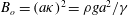 $B_{o}=(a\unicode[STIX]{x1D705})^{2}=\unicode[STIX]{x1D70C}ga^{2}/\unicode[STIX]{x1D6FE}$
, respectively, of the previous study (Ledesma-Alonso et al.
Reference Ledesma-Alonso, Benzaquen, Salez and Raphaël2016). At low speed, the profiles are nearly symmetric and show a cavity below the external pressure field. When the reduced speed reaches
$B_{o}=(a\unicode[STIX]{x1D705})^{2}=\unicode[STIX]{x1D70C}ga^{2}/\unicode[STIX]{x1D6FE}$
, respectively, of the previous study (Ledesma-Alonso et al.
Reference Ledesma-Alonso, Benzaquen, Salez and Raphaël2016). At low speed, the profiles are nearly symmetric and show a cavity below the external pressure field. When the reduced speed reaches
 $V\sim 1$
, there is an accumulation of material at the front (
$V\sim 1$
, there is an accumulation of material at the front (
 $U>0$
) and a stretching of the cavity behind the centre of the pressure field (
$U>0$
) and a stretching of the cavity behind the centre of the pressure field (
 $U<0$
). At high speed, comet-like shapes surrounded by undulations are observed, with an overall extent that can greatly exceed the size of the pressure field.
$U<0$
). At high speed, comet-like shapes surrounded by undulations are observed, with an overall extent that can greatly exceed the size of the pressure field.
A comparison between the main features of the present elastohydrodynamic case and the ones previously reported for the viscocapillary case (Ledesma-Alonso et al. Reference Ledesma-Alonso, Benzaquen, Salez and Raphaël2016) is shown in figures 3 and 4. Note that the classical and elastic Bond numbers have been set to an identical value, in order to observe the differences between these two cases, for a disturbance with the same ratio between its size and the characteristic length of the problem. In the transverse cut of figure 3(a), although the trends are similar, we observe that the oscillations are more pronounced in the elastohydrodynamic case. In the longitudinal cut of figure 3(b), it is interesting to notice the existence of oscillations at the front of the pressure disturbance in the elastohydrodynamic case, which for the viscocapillary case are damped more quickly. Additionally, at the rear of the disturbance, a longer decay length of the wake is observed for the elastohydrodynamic case. Also, the amplitude of the surface deformation is slightly larger for the elastohydrodynamic case. Similarly, figure 4 highlights the effects of varying the Bond and elastic Bond numbers: mainly, the smaller the disturbance (i.e. smaller Bond and elastic Bond numbers), the more oscillations we observe.

Figure 3. (a,c,e) Normalized height profile as a function of the transverse coordinate
 $Y$
, for a fixed longitudinal coordinate
$Y$
, for a fixed longitudinal coordinate
 $U=-20$
and different values of the reduced speeds
$U=-20$
and different values of the reduced speeds
 $V$
, as indicated. (b,d,f) Normalized height profile as a function of the longitudinal coordinate
$V$
, as indicated. (b,d,f) Normalized height profile as a function of the longitudinal coordinate
 $U=X-VT$
, for a fixed transverse coordinate
$U=X-VT$
, for a fixed transverse coordinate
 $Y=0$
and different values of the reduced speeds
$Y=0$
and different values of the reduced speeds
 $V$
, as indicated. In all panels, the orange curves correspond to the elastohydrodynamic case of (3.4) and (3.5) with
$V$
, as indicated. In all panels, the orange curves correspond to the elastohydrodynamic case of (3.4) and (3.5) with
 $B_{el}=1$
, whereas the blue curves correspond to the viscocapillary case (Ledesma-Alonso et al.
Reference Ledesma-Alonso, Benzaquen, Salez and Raphaël2016) with a Lorentzian pressure distribution and
$B_{el}=1$
, whereas the blue curves correspond to the viscocapillary case (Ledesma-Alonso et al.
Reference Ledesma-Alonso, Benzaquen, Salez and Raphaël2016) with a Lorentzian pressure distribution and
 $B_{o}=1$
.
$B_{o}=1$
.

Figure 4. (a,c,e) Normalized height profile as a function of the transverse coordinate
 $Y$
, for fixed longitudinal coordinate
$Y$
, for fixed longitudinal coordinate
 $U=-20$
and reduced speed
$U=-20$
and reduced speed
 $V=10$
. (b,d,f) Normalized height profile as a function of the longitudinal coordinate
$V=10$
. (b,d,f) Normalized height profile as a function of the longitudinal coordinate
 $U=X-VT$
, for a fixed transverse coordinate
$U=X-VT$
, for a fixed transverse coordinate
 $Y=0$
and reduced speed
$Y=0$
and reduced speed
 $V=10$
. In all panels, the orange curves correspond to the elastohydrodynamic case of (3.4) and (3.5) for different values of the elastic Bond number
$V=10$
. In all panels, the orange curves correspond to the elastohydrodynamic case of (3.4) and (3.5) for different values of the elastic Bond number
 $B_{el}$
, as indicated, whereas the blue curves correspond to the viscocapillary case (Ledesma-Alonso et al.
Reference Ledesma-Alonso, Benzaquen, Salez and Raphaël2016) with a Lorentzian pressure distribution and different values of the Bond number
$B_{el}$
, as indicated, whereas the blue curves correspond to the viscocapillary case (Ledesma-Alonso et al.
Reference Ledesma-Alonso, Benzaquen, Salez and Raphaël2016) with a Lorentzian pressure distribution and different values of the Bond number
 $B_{o}$
, as indicated.
$B_{o}$
, as indicated.
A detailed description of the numerical analysis, which includes the computational size and discretization of the spatial frequency domain and the corresponding convergence test, employed to obtain the above-mentioned and the following results, is given in the supplementary material available at https://doi.org/10.1017/jfm.2017.584.
4 Wave resistance
As the pressure disturbance moves atop the elastic sheet, it generates the previously discussed surface deformation, which is intimately coupled to the motion of the underlying liquid. As a consequence of the viscous nature of the latter, a continuous dissipation of energy takes place, and the moving disturbance experiences a force opposing its motion. This so-called wave resistance
 $r$
is given by Havelock’s formula, usually used in the inviscid theory of waves (Havelock Reference Havelock1932; Raphaël & De Gennes Reference Raphaël and De Gennes1996), but still valid for a viscous fluid:
$r$
is given by Havelock’s formula, usually used in the inviscid theory of waves (Havelock Reference Havelock1932; Raphaël & De Gennes Reference Raphaël and De Gennes1996), but still valid for a viscous fluid:
 $$\begin{eqnarray}\displaystyle r=\iint \unicode[STIX]{x1D713}_{ext}{\displaystyle \frac{\unicode[STIX]{x2202}h}{\unicode[STIX]{x2202}x}}\,\text{d}x\,\text{d}y. & & \displaystyle\end{eqnarray}$$
The power
 $vr$
must be furnished by the operator in order to maintain a constant disturbance speed
$vr$
must be furnished by the operator in order to maintain a constant disturbance speed
 $v$
(Ledesma-Alonso et al.
Reference Ledesma-Alonso, Benzaquen, Salez and Raphaël2016).
$v$
(Ledesma-Alonso et al.
Reference Ledesma-Alonso, Benzaquen, Salez and Raphaël2016).
With the notation introduced above, the dimensionless wave resistance
 $R$
reads
$R$
reads
 $$\begin{eqnarray}R={\displaystyle \frac{r\unicode[STIX]{x1D705}_{el}}{\unicode[STIX]{x1D70C}gh_{0}^{2}}}=\unicode[STIX]{x1D6E4}_{el}\iint \unicode[STIX]{x1D6F9}(U,Y){\displaystyle \frac{\unicode[STIX]{x2202}\unicode[STIX]{x1D701}}{\unicode[STIX]{x2202}U}}\,\text{d}U\,\text{d}Y.\end{eqnarray}$$
Then, the substitution of (3.4) into (4.2) yields
 $$\begin{eqnarray}\displaystyle R={\displaystyle \frac{\unicode[STIX]{x1D6E4}_{el}^{2}V}{4\unicode[STIX]{x03C0}^{2}}}\iint {\displaystyle \frac{K^{2}(K^{2}+Q^{2})|\widehat{\unicode[STIX]{x1D6F9}}(K,Q)|^{2}}{K^{2}V^{2}+(K^{2}+Q^{2})^{2}[1+(K^{2}+Q^{2})^{2}]^{2}}}\,\text{d}K\,\text{d}Q. & & \displaystyle\end{eqnarray}$$
Invoking the polar coordinates,
 $K=\unicode[STIX]{x1D70C}\cos \unicode[STIX]{x1D703}$
and
$K=\unicode[STIX]{x1D70C}\cos \unicode[STIX]{x1D703}$
and
 $Q=\unicode[STIX]{x1D70C}\sin \unicode[STIX]{x1D703}$
, and assuming an axisymmetric pressure field
$Q=\unicode[STIX]{x1D70C}\sin \unicode[STIX]{x1D703}$
, and assuming an axisymmetric pressure field
 $\widehat{\unicode[STIX]{x1D6F9}}(\unicode[STIX]{x1D70C})$
, allows us to integrate over
$\widehat{\unicode[STIX]{x1D6F9}}(\unicode[STIX]{x1D70C})$
, allows us to integrate over
 $\unicode[STIX]{x1D703}$
and get the expression
$\unicode[STIX]{x1D703}$
and get the expression
 $$\begin{eqnarray}\displaystyle R={\displaystyle \frac{\unicode[STIX]{x1D6E4}_{el}^{2}}{2\unicode[STIX]{x03C0}V}}\int _{0}^{\infty }\left[1-{\displaystyle \frac{\unicode[STIX]{x1D70C}(\unicode[STIX]{x1D70C}^{4}+1)}{\sqrt{V^{2}+\unicode[STIX]{x1D70C}^{2}(\unicode[STIX]{x1D70C}^{4}+1)^{2}}}}\right]|\widehat{\unicode[STIX]{x1D6F9}}(\unicode[STIX]{x1D70C})|^{2}\unicode[STIX]{x1D70C}^{3}\,\text{d}\unicode[STIX]{x1D70C}. & & \displaystyle\end{eqnarray}$$
Equations (3.5) and (4.4) allow us to compute numerically the wave resistance. The results are presented in figure 5. At low speed, the wave resistance shows a linear dependence on
 $V$
; at high speed, it decreases inversely proportional to
$V$
; at high speed, it decreases inversely proportional to
 $V$
; and at intermediate speed, it shows a maximum at the cross-over between the two mentioned regimes. In addition, the larger
$V$
; and at intermediate speed, it shows a maximum at the cross-over between the two mentioned regimes. In addition, the larger
 $B_{el}$
, i.e. the wider the pressure field, the lower the wave resistance; and the smaller
$B_{el}$
, i.e. the wider the pressure field, the lower the wave resistance; and the smaller
 $B_{el}$
, i.e. the narrower the Lorentzian pressure field, the more the wave resistance approaches that associated with the Dirac pressure field (
$B_{el}$
, i.e. the narrower the Lorentzian pressure field, the more the wave resistance approaches that associated with the Dirac pressure field (
 $\widehat{\unicode[STIX]{x1D6F9}}=1$
), as expected. Interestingly, the Dirac case shows a more gentle slope of
$\widehat{\unicode[STIX]{x1D6F9}}=1$
), as expected. Interestingly, the Dirac case shows a more gentle slope of
 $V^{-1/5}$
at high speed. All these asymptotic behaviours will be recovered analytically and explained in the following subsections. In addition, we observe that the maximal wave resistance is bounded by that of the Dirac case. Indeed, a Dirac pressure field excites all the wavelengths, whereas a Lorentzian pressure field cuts off the large wavelengths.
$V^{-1/5}$
at high speed. All these asymptotic behaviours will be recovered analytically and explained in the following subsections. In addition, we observe that the maximal wave resistance is bounded by that of the Dirac case. Indeed, a Dirac pressure field excites all the wavelengths, whereas a Lorentzian pressure field cuts off the large wavelengths.

Figure 5. Normalized wave resistance
 $R/\unicode[STIX]{x1D6E4}_{el}^{2}$
, as given by (3.5) and (4.4), as a function of the reduced speed
$R/\unicode[STIX]{x1D6E4}_{el}^{2}$
, as given by (3.5) and (4.4), as a function of the reduced speed
 $V$
, for various elastic Bond numbers
$V$
, for various elastic Bond numbers
 $B_{el}$
as indicated. The Dirac limit (
$B_{el}$
as indicated. The Dirac limit (
 $B_{el}\rightarrow 0$
) is indicated. The vertical dashed lines indicate the position of the maximal wave resistance (see (4.11)), for each value of
$B_{el}\rightarrow 0$
) is indicated. The vertical dashed lines indicate the position of the maximal wave resistance (see (4.11)), for each value of
 $B_{el}$
.
$B_{el}$
.
4.1 Low-speed regime
As seen in the low-speed regime of figure 5, the wave resistance shows a linear rise with the speed
 $V$
. Indeed, using the Dirac pressure field, we get the following asymptotic expression from (4.4) as
$V$
. Indeed, using the Dirac pressure field, we get the following asymptotic expression from (4.4) as
 $V\rightarrow 0$
:
$V\rightarrow 0$
:
 $$\begin{eqnarray}\displaystyle R\sim {\displaystyle \frac{\unicode[STIX]{x1D6E4}_{el}^{2}V}{32}}. & & \displaystyle\end{eqnarray}$$
Similarly, using the Lorentzian pressure field of (3.5), the wave resistance reads in the low-speed regime:
 $$\begin{eqnarray}\displaystyle R\sim {\displaystyle \frac{\unicode[STIX]{x1D6E4}_{el}^{2}V}{4\unicode[STIX]{x03C0}}}{\mathcal{F}}(B_{el}), & & \displaystyle\end{eqnarray}$$
where
 $$\begin{eqnarray}{\mathcal{F}}(B_{el})=\int _{0}^{+\infty }\frac{\unicode[STIX]{x1D70C}\exp (-2\sqrt{B_{el}}\unicode[STIX]{x1D70C})}{(\unicode[STIX]{x1D70C}^{4}+1)^{2}}\,\text{d}\unicode[STIX]{x1D70C}.\end{eqnarray}$$
In the limit of a wide pressure field,
 $B_{el}\gg 1$
, one obtains
$B_{el}\gg 1$
, one obtains
 $$\begin{eqnarray}\displaystyle {\mathcal{F}}(B_{el})\sim {\displaystyle \frac{1}{4B_{el}}}. & & \displaystyle\end{eqnarray}$$
4.2 High-speed regime
In the high-speed regime of figure 5, one has two distinct scaling behaviours with
 $V$
. Indeed, for the Dirac case, using the asymptotic development of (4.4) as
$V$
. Indeed, for the Dirac case, using the asymptotic development of (4.4) as
 $V\rightarrow \infty$
, one gets
$V\rightarrow \infty$
, one gets
 $$\begin{eqnarray}\displaystyle R\sim -{\displaystyle \frac{\unicode[STIX]{x1D6E4}_{el}^{2}\unicode[STIX]{x1D6E4}(-2/5)\unicode[STIX]{x1D6E4}(9/10)}{20\unicode[STIX]{x03C0}^{3/2}}}{\displaystyle \frac{1}{V^{1/5}}}, & & \displaystyle\end{eqnarray}$$
where
 $\unicode[STIX]{x1D6E4}(z)$
is the Gamma function, and has no relation with the dimensionless quantity
$\unicode[STIX]{x1D6E4}(z)$
is the Gamma function, and has no relation with the dimensionless quantity
 $\unicode[STIX]{x1D6E4}_{el}$
, which has been defined in § 2.
$\unicode[STIX]{x1D6E4}_{el}$
, which has been defined in § 2.
In contrast, for the Lorentzian pressure field of (3.5), we obtain
 $$\begin{eqnarray}\displaystyle R\sim {\displaystyle \frac{3\unicode[STIX]{x1D6E4}_{el}^{2}}{16\unicode[STIX]{x03C0}B_{el}^{2}}}{\displaystyle \frac{1}{V}}. & & \displaystyle\end{eqnarray}$$
From the comparison of (4.9) and (4.10), we remark that the wave resistance for a realistic finite-size pressure field decays much faster than for the singular Dirac pressure field.
4.3 Maximal wave resistance
As observed in figure 5, all the curves show a maximum for a certain speed
 $V^{\ast }(B_{el})$
. An estimation of this speed can be obtained by balancing the low-speed and high-speed asymptotic expressions of the wave resistance in the Lorentzian case:
$V^{\ast }(B_{el})$
. An estimation of this speed can be obtained by balancing the low-speed and high-speed asymptotic expressions of the wave resistance in the Lorentzian case:
 $$\begin{eqnarray}\displaystyle V^{\ast }\sim \sqrt{{\displaystyle \frac{3}{4{\mathcal{F}}(B_{el})B_{el}^{2}}}}. & & \displaystyle\end{eqnarray}$$
Therefore, at high elastic Bond number, one finds
 $$\begin{eqnarray}V^{\ast }\sim \sqrt{{\displaystyle \frac{3}{B_{el}}}}\end{eqnarray}$$
and
 $$\begin{eqnarray}R(V^{\ast })\sim {\displaystyle \frac{\sqrt{3}\unicode[STIX]{x1D6E4}_{el}^{2}}{16\unicode[STIX]{x03C0}B_{el}^{3/2}}}.\end{eqnarray}$$
The limit of the maximal wave resistance as
 $B_{el}\rightarrow 0$
can be obtained by balancing the low-speed and high-speed asymptotic expressions of the wave resistance in the Dirac case:
$B_{el}\rightarrow 0$
can be obtained by balancing the low-speed and high-speed asymptotic expressions of the wave resistance in the Dirac case:
 $$\begin{eqnarray}\displaystyle V^{\ast }\sim \left[-{\displaystyle \frac{8\unicode[STIX]{x1D6E4}(-2/5)\unicode[STIX]{x1D6E4}(9/10)}{5\unicode[STIX]{x03C0}^{3/2}}}\right]^{5/6} & & \displaystyle\end{eqnarray}$$
and thus
 $$\begin{eqnarray}\displaystyle R(V^{\ast })\sim {\displaystyle \frac{\unicode[STIX]{x1D6E4}_{el}^{2}}{32}}\left[-{\displaystyle \frac{8\unicode[STIX]{x1D6E4}(-2/5)\unicode[STIX]{x1D6E4}(9/10)}{5\unicode[STIX]{x03C0}^{3/2}}}\right]^{5/6}. & & \displaystyle\end{eqnarray}$$
The asymptotic behaviours for low and high elastic Bond number, given by (4.12) and (4.14) for
 $V^{\ast }$
, and by (4.13) and (4.15) for
$V^{\ast }$
, and by (4.13) and (4.15) for
 $R(V^{\ast })$
, are also represented in figure 6.
$R(V^{\ast })$
, are also represented in figure 6.

Figure 6. Computed values of the normalized maximal wave resistance
 $R(V^{\ast })/\unicode[STIX]{x1D6E4}_{el}^{2}$
(blue) and the corresponding speed
$R(V^{\ast })/\unicode[STIX]{x1D6E4}_{el}^{2}$
(blue) and the corresponding speed
 $V^{\ast }$
(red), as functions of the elastic Bond number
$V^{\ast }$
(red), as functions of the elastic Bond number
 $B_{el}$
, according to (4.7) and (4.11). The dashed lines represent the Dirac limits given in (4.14) and (4.15).
$B_{el}$
, according to (4.7) and (4.11). The dashed lines represent the Dirac limits given in (4.14) and (4.15).
Surprisingly, this behaviour is qualitatively different from the viscocapillary case (Ledesma-Alonso et al.
Reference Ledesma-Alonso, Benzaquen, Salez and Raphaël2016) for which the maximal wave resistance diverges in the Dirac limit. These results are summarized in figure 6. Therein, the maximal wave resistance decreases as
 $B_{el}^{-3/2}$
at large
$B_{el}^{-3/2}$
at large
 $B_{el}$
, and saturates to a finite value in the Dirac limit. The corresponding speed
$B_{el}$
, and saturates to a finite value in the Dirac limit. The corresponding speed
 $V^{\ast }$
decreases as
$V^{\ast }$
decreases as
 $B_{el}^{-1/2}$
at large
$B_{el}^{-1/2}$
at large
 $B_{el}$
, and saturates as well in the Dirac limit.
$B_{el}$
, and saturates as well in the Dirac limit.
5 Conclusion
We have presented a theoretical investigation of the effects of a moving pressure disturbance above a thin elastic sheet placed atop a narrow viscous film. From the elastohydrodynamic lubrication model, we computed both the wake and the associated wave resistance experienced by the operator. A central dimensionless parameter of this study appeared to be the so-called elastic Bond number, measuring the ratio of gravity to elastic bending. As in the viscocapillary case, the wave resistance was observed to have a global maximum – a point it might be interesting to control for energy-saving purposes. Finally, we conclude our study by an asymptotic analysis of the low-speed and high-speed regimes. These results are relevant to a wide class of geophysical, biological and engineering problems, and may have implications in nanorheology, as well as wave propagation in metamaterials.
Acknowledgements
The authors thank V. Démery, K. Dalnoki-Veress, H. Stone and A. Eddi for interesting discussions. They acknowledge financial support from the Global Station for Soft Matter – a project of Global Institution for Collaborative Research and Education at Hokkaido University.
Supplementary material
Supplementary material is available at https://doi.org/10.1017/jfm.2017.584.


