


Introduction
The recent years have witnessed an increase in demand for wireless handheld devices with high data rate. Consequently, this has accelerated the need for compact multiband antennas. In particular, miniaturization, multiband operation, integration, versatility, good gain, and efficiencies are the crucial factors that affect the applicability of the antenna in future wireless devices. Multiband antennas provide an effective integration of several communication standards, in addition to low-cost and high data rate features. Multiband antennas can be designed by feeding techniques [Reference Sarkar, Saurav and Srivastava1–Reference Wu, Wang, Zheng and Li4], etching slots [Reference Mehdipour, Sebak, Trueman and Denidni5–Reference Ali, Pathan and Biradar7], adding multi-branched strips, fractals [Reference Anguera, Puente, Borja and Soler8], etc.
Slots create some sort of discontinuity in the electric current path leading to positive impact on input impedance thereby creating additional resonance frequencies. In [Reference Chen, Yang and Sim9], horizontal feeding structures and a single open slot aided in multiband operation. In [Reference Lee, Lim, Yoon, Hong and Kim10, Reference Yuan, Cao and Wang11] multiple resonances are obtained with the aid of several slots that operate using half wavelength modes.
Recently, metamaterials have garnered significant attention for implementing smart antennas due to the exclusive and exotic properties such as the possibility of tailoring μ and ε, negative refractive index, anti-parallel group, and phase velocities. The application of the aforementioned properties leads to miniaturization, bandwidth enhancement, multiband operation, and better radiation efficiency in a metamaterial-loaded antenna. The metamaterial consists of different types of structures such as complimentary split ring resonator (SRR), SRRs), pentagonal SRR, triangular SRR, L-dumbbell-shaped, etc. Based on these metamaterial structures, various multiband antennas have been reported in the literature [Reference Sharma, Mulchandani, Gupta and Chaudhary12–Reference Kukreja, Kumar Choudhary and Kumar Chaudhary14]. A triple band metamaterial-based multiband antenna using L-dumbbell-shaped unit cells was proposed in [Reference Sharma, Mulchandani, Gupta and Chaudhary12]. SRRs have also employed for achieving multiband operation [Reference Ali and Biradar13, Reference Kukreja, Kumar Choudhary and Kumar Chaudhary14]. Using the aforementioned techniques, multiple operating bands have been obtained. However, difficulties exist in realizing additional number of operating bands without a trade off in size. The approach adopted in this paper consists of designing low profile compact multiband antennas with the utilization of slots, fractals, and metamaterials which outperforms the antennas studied in literature [Reference Ali and Biradar13, Reference Wen15–Reference Ali and Biradar21], in terms of size, number of operating band, and bandwidth obtained, as illustrated in Table 1.
Table 1. Comparison of the proposed design with those in the state-of-art literature

This research presents a compact quad-band metamaterial fractal slot antenna for the lower WiMAX/middle WiMAX/Satellite TV/X-band system. The antenna consists of a circular monopole, Sierpinski triangle, L-shaped slot as the radiating part, and metamaterial circular SRR as the ground plane. The antenna has a compact dimension of 30 mm × 24.8 mm × 1.6 mm and is printed on FR4 substrate with dielectric constant (ε r) and loss tangent (δ) of 4.4 and 0.02, respectively. The antenna exhibits resonance at about 3.3, 5.5, 7.3, and 9.9 GHz in simulation and at about 3.1, 5.52, 7.31, 9.72 GHz under measurement, respectively. There exists a good agreement between the simulated and manufactured results of the proposed configuration. The antenna has less size, more number of resonating bands, and good radiation characteristics as compared with those studied in the literature [Reference Ali and Biradar13, Reference Wen15–Reference Ali and Biradar21].
Antenna design
The design steps for the proposed four-band antenna are illustrated in Fig. 1. Firstly, a circular monopole antenna with partial ground structure is designed as depicted in configuration “#1” of Fig. 1. The resonance frequency (f r) of this circular monopole can be calculated as [Reference Balanis22].
 $$\; f_r = \displaystyle{{1.8412{\rm \;} \times c} \over {2\pi \times a \times \sqrt {\varepsilon _{eff}}}},$$
 $$a = r\sqrt {\left\{ {1 + \displaystyle{{4H} \over {2\pi \times r{\rm \;} \times \varepsilon _r}}\left[ {{\rm ln}\left( {\displaystyle{{2\pi \times r} \over {4H}}} \right) + 1.77} \right]} \right\}},$$
where c is the speed of light in m/sec, a and r are the effective area and radius of the circular monopole, and ε eff is the effective dielectric constant, respectively.

Fig. 1. Evolution stages.
From Fig. 2, it can be observed that this antenna does not operate at any band. In order to make antenna “#1” to resonate at some useful band, a circular metamaterial SRR is etched out in the ground plane, as illustrated in configuration “#2” of Fig. 1. The introduction of circular SRR introduces a narrow resonance at 3.3 GHz (middle WiMAX) (Fig. 2). The detail analysis of this metamaterial circular SRR is further discussed in Section “Analysis of metamaterial circular SRR”. To make the antenna “#2” operate at more bands, the circular monopole is modified into the shape of Sierpinski triangle as illustrated in configuration “#3” of Fig. 2. The introduction of Sierpinski triangle makes the antenna to operate at 5.5 (upper WiMAX) and 7.3 GHz (Satellite TV), as illustrated in Fig. 2. In order to further enhance the operating abilities of antenna “#3”, an L-shaped slot is etched out in the circular monopole just below the Sierpinski triangle as illustrated in configuration “#4” of Fig. 2. The introduction of L-shaped slot creates a discontinuity in the radiating monopole. Due to this discontinuity, the surface electrical current length path increases [Reference Ali, Mohammad Saadh, Biradar, Anguera and Andujar23]. This rise in current path length affects the input impedance of antenna, which tends the antenna to exhibit additional resonance at 9.9 GHz (X-band), as illustrated in Fig. 2. The detailed layout of the proposed antenna “#4” is further depicted in Fig. 3.

Fig. 2. Evolution stage simulated S 11.

Fig. 3. Layout of antenna showing the front and the back patches.
The antenna consists of a Sierpinski triangle and L-shaped slot (L 1 × L 3 × L 4 × L 2) as the radiating part and metamaterial circular SRR as the ground plane. The microstrip feed line (F L × F W) is used to provide an impedance of 50 Ω. The rectangular stub (G 2 × G 3) present in the ground plane of the proposed design is used to connect circular SRR with the ground plane. The ground plane (G L × W) is used to adjust operating bands 3 and 4, respectively. The complete simulation of antenna is done on HFSS v. 13.0 software using finite element method.
The optimized dimensions (mm) of the antenna are: L = 30, W = 24.8, D = 18.9, F L = 10.4, F W = 2.3, T = 16.3, T 1 = 8.1, T 2 = 4.1, T 3 = 2.05, L 1 = 5.8, L 2 = 1.1, L 3 = 11.6, L 4 = 0.8, G L = 19, G 1 = 11, G 2 = 3, G 3 = 0.7, S 1 = 5.25, S 2 = 4.31, S 3 = 3.4, S 4 = 2.56, S 5 = 1, S 6 = 1, and S 7 = S 8 = S = 1.8.
Analysis of metamaterial circular SRR
The circular split ring presented in this paper is the fundamental geometry for designing of sub-wavelength magnetic metamaterial resonators. The circular SRR is formed by two metallic rings (resonator) with a gap between them, as illustrated in Fig. 4(a), and its modeled equivalent circuit is illustrated in Fig. 4(b). The gap (S 7 = S 8 = S) between the inner and outer split rings is same. Due to the applied external H-field, an EMF appears around the SRR, which couples two rings with the current passing from the outer ring to the inner ring through a distributed capacitance formed due to the ring spacing (S 6), and thus the entire structure behaves as LC circuit. The resonant frequency of this SRR can be calculated as (3).
 $$\omega _r = \; \displaystyle{1 \over {\sqrt {L_{tot}C_{tot}}}},$$
where L tot is the total inductance contributed by metallic ring calculated as (4) and C tot is the total capacitance calculated as (5) [Reference Saha and Siddiqui24].
 $$L_{tot} = 0.00021\left( {2.303{\rm lo}{\rm g}_{10}\displaystyle{{4y} \over c} - 2.451)} \right),$$
where y = 2πS 1 − S
 $$C_{tot} = \displaystyle{{(C_x + C_{gs})} \over 2}.$$
Fig. 4. Analysis of circular SRR. (a) Detailed configuration; (b) equivalent circuit; (c) retrieved S-parameters; and (d) waveguide medium to retrieve S-parameter.
Also, C 0 = C 1 = C x and C S7 = C S8 = C gs.
Figure 4(c) illustrates the retrieved S-parameters characteristics of the proposed circular SRR obtained through waveguide medium [Reference Smith, Schultz, Markoš and Soukoulis25]. To extract the S-parameters, circular SRR is placed inside the waveguide medium as illustrated in Fig. 4(d). It can be observed that the placed SRR is provided with perfect magnetic conductor and perfect electric conductor boundary conditions. Excitation of SRR is achieved by the electromagnetic wave via the input port. Correspondingly, via the output port, S 21 and S 11 are computed. It can be observed that the pass-band phenomenon of the circular SRR is observed at 3.3 GHz (Fig. 5(c)), which at the same time verifies our theoretical analysis relation  $\omega _r = \; 1/\sqrt {L_{tot}C_{tot}} $.

Fig. 5. Parametric studies for (a) F w, (b) L 3, (c) G L, and (d) S variations.
Studies of the antenna
To observe the operational performance of the antenna with the variation in the optimized dimensions, its parametric analysis is carried out. The parametric study is done in four conditions, they are: (1) variation of feed width (F W) on overall impedance matching of the antenna, (2) variation in length (L 3) of L-shaped slot, (3) variation in the ground plane length (G L), and (4) variation in the gap (S) of metamaterial circular SRR. All these studies are done by varying F W, L 3, G L, and S while keeping other design dimensions constant as depicted in Fig. 5. For condition 1, F W is varied from 1.3 to 2.8 mm at a step of 0.5 mm as illustrated in Fig. 5(a). It is seen that, due to the variation of F W, bands 1 and 4 reflection coefficient (S 11) changes and there is a frequency shift at bands 2 and 3, respectively. The best overall impedance matching is observed at F W = 2.3 mm. For condition 2, length (L 3) of L-shaped slot is varied at a step of 0.5 mm from 10.6 to 12.1 mm, as illustrated in Fig. 5(b). It can be observed that as L 3 varies, band 2 is drastically affected. At L 3 = 10.6 mm, no operation of band 2 is observed (since S 11 shifts above −10 dB). Also, at bands 3 and 4, shift in operating band and in S 11 value is observed. At band 1, there is only change in S 11 value. The best operation is achieved at L 3 = 11.6 mm. For condition 3, G L is varied from 18 to 19.5 mm, at a step of 0.5 mm as depicted in Fig. 5(c). As G L varies, there is a frequency shift and change in the value of S 11 at bands 1, 2, 3, and 4, respectively. The best performance is achieved for G L = 19 mm. Lastly for condition 4, the metamaterial split gap (S) present on the ground plane of the antenna is varied from 0.8 to 2.3 mm, to observe its effects on the performance of the proposed antenna. The study shows that as S varies, the S 11 value at bands 1, 2, and 4 changes as illustrated in Fig. 5(d). At band 3, for S = 0.8, 1.3, and 2.3 mm, the S 11 shifts above −10 dB. The best result is obtained at S = 1.8 mm.
Results
The proposed multiband antenna depicted in Fig. 3 has been studied using HFSS v.13.0 software and is printed on FR4 substrate having a dielectric constant, thickness, and loss tangent of 4.4, 1.6 mm, and 0.01, respectively, as illustrated in Fig. 6. The antenna has a compact dimension of 0.33λ 0 × 0.27λ 0 × 0.01λ 0 (30 mm × 24.8 mm × 1.6 mm), at a lower frequency of 3.3 GHz. The simulated S 11 of the proposed design in HFSS is illustrated in Fig. 7(a), and the set-up to measure this simulated S 11 using vector network analyzer (VNA) is illustrated in Fig. 7(b). The comparison between the simulated and measured S 11 results of the proposed design is further illustrated in Fig. 8. It can be observed that the antenna operates at 3.3 (middle WiMAX), 5.5 (upper WiMAX), 7.3 (Satellite TV), and 9.9 GHz (X-band) in simulation and at 3.1, 5.52, 7.31, and 9.72 GHz in measurement, respectively. The antenna has S 11 < −10 dB bandwidth of about 200 MHz (3.24–3.44 GHz), 310 MHz (5.31–5.62 GHz), 530 MHz (6.99–7.52 GHz), and 300 MHz (9.78–10.08 GHz) under simulation, and about 110 MHz (3.04–3.15 GHz), 280 MHz (5.44–5.72 GHz), 960 MHz (6.76–7.72 GHz), and 560 MHz (9.42–9.98 GHz) in measurement, respectively.

Fig. 6. Fabricated model of the proposed design. (a) Front part and (b) back part.

Fig. 7. (a) Simulated S 11 in HFSS, (b) S 11 measurement set-up using VNA, and (c) snap shot of VNA screen.

Fig. 8. Compared S 11 results of the proposed design.
The simulated results best comply with the measured results. Slight deviation may be due to the use of cables and soldering of SMA connector, fabrication tolerance, and the VNA cable used for the measurement of S 11. However, the achieved bandwidth is sufficient to meet the requirement of WiMAX, Satellite TV, and X-band applications. The summarized result of the antenna is depicted in Table 2.
Table 2. Summarized result of the designed antenna

Radiation pattern
The set-up to measure the radiation pattern of the designed antenna is illustrated in Fig. 9. A standard yagi uda antenna is used as a reference antenna to measure the far-field radiation pattern of the proposed design. This far-field measurements are based on R ≫ 2D 2/λ (Friis equation). The radiation pattern of the proposed design is measured at a step of 5° from 0 to 360°, at the frequencies 3.10, 5.52, 7.31, and 9.72 GHz, both in xz-plane (E θ and E φ) and yz-plane (E θ and E φ), as illustrated in Fig. 10 and 11, respectively.

Fig. 9. Set-up to measure the radiation characteristics of the proposed design.

Fig. 10. Normalized radiation characteristics in xz-plane for (a) 3.1, (b) 5.52, (c) 7.31, and (d) 9.72 GHz, respectively.
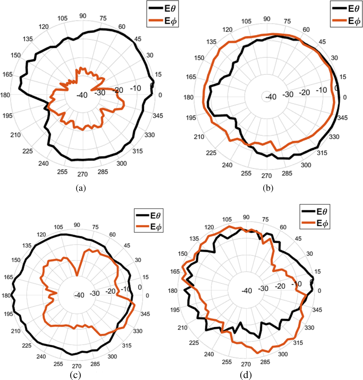
Fig. 11. Normalized radiation characteristics in yz-plane for (a) 3.1, (b) 5.52, (c) 7.31, and (d) 9.72 GHz, respectively.
From Fig. 10 and 11, it is observed that antenna has almost bi-directional pattern in xz-plane (E θ) and omnidirectional pattern in yz-plane (E θ). The glitches in the pattern may be due to the electromagnetic interference from the nearby devices.
Gain
The peak gain of the antenna is depicted in Fig. 12. A peak gain of about 1.35, 1.0, 1.07, and 1.75 dB are observed for 3.1, 5.52, 7.31, and 9.72 GHz, respectively.

Fig. 12. Peak Gain (dB) of the proposed design.
Conclusion
The design of a novel planar four-band fractal antenna loaded with L-shaped slot and metamaterial is presented. The antenna has a compact dimension of 30 mm × 24.8 mm × 1.6 mm and provides the tuning range of about 11% (3.04–3.15 GHz), 28% (5.44–5.72 GHz), 96% (6.76–7.72 GHz), and 56% (9.42–9.98 GHz), at the respective measured operating bands. Parametric studies shows that the slight change in the optimized dimensions affect the surface current distribution, which in turn degrades the operational performances of the designed antenna. Simulations and measurements are used to analyze the performance of the antenna in terms of reflection coefficient, radiation pattern, and gain. The results show that the antenna has four frequencies at about 3.1, 5.52, 7.31, and 9.72 GHz, with good impedance matching and stable radiation characteristics, which can easily cover WiMAX, Satellite TV, and X-band applications.
Acknowledgement
The authors express their gratitude to Mrs. Sameena Pathan, Manipal Institute of Technology, MAHE, Manipal, India, for his extensive support and contribution in carrying out this research work.
 Tanweer is working as an Assistant Professor in the School of Electronics and Communication Engineering, REVA University. He has completed B.Tech. in Electronics and Communication Engineering from Punjab Technical University Punjab, M.E. in Wireless Communication from Birla Institute of Technology, Mesra Ranchi and currently pursuing his Ph.D. from REVA University in RF and Microwave domain. He has more than 5 years of teaching and research experience. He has over 35 research publications in reputed international journals and conferences. Some of the journals where his research articles have been published are Microwave Optical Technology Letters (MOTL) Wiley; Progress in Electromagnetic Research C, AEU-Elsevier, Internet Technology Letters Wiley, Transaction on Engineering Sciences, and IEEE XPLORE having very good impact factors. His research interests include antennas, reconfigurable antennas, waveguides, microwave filter designing, etc. He is a reviewer of MOTL, AEU-Elsevier, PIER C, WPC-Springer, IJMWT-Cambridge University Press, International Journal of Antennas and Propagation-Hindawi, Advanced Electromagnetics, KSII Transaction, and IEEE-AWPL.
 Rajashekhar C. Biradar is working as Director, School of ECE, REVA University, Bangalore. He has over 26 years of teaching and research experience. He has many research publications in reputed national/international journals and conferences. Some of the journals where his research articles published are Elsevier, IET, Springer, Wiley, and IOS Press, having good impact factors. He has published 45 papers in peer-reviewed national and international journals, 70 papers in reputed national and international conferences, and three book chapters. As per Google Scholar, he has more than 254 citations (h-index = 8 and i-10index = 8) (June.2016). He is involved in research which covers various sorts of wireless networks such as ad hoc networks, sensor networks, mesh networks, network security, antenna design, etc. Currently, he is guiding eight PhD students. He is a reviewer of various reputed journals and conferences and chaired many conferences. He is a Fellow IETE (FIETE) India, member IE (MIE) India, member ISTE (MISTE) India, senior member of IEEE (SMIEEE) USA, and member of IACSIT. He has been listed in Marquis’ Who's Who in the World (2012 Edition), USA and Top 100 Engineers by IBC, UK.
 Mohammad Saadh AW has completed B.Tech in Electronics and Communication Engineering in 2017 from REVA University and is working toward JRF in Society for Applied Microwave Electronics Engineering and Research (SAMEER) in the field of antenna design. He is currently continuing his research on microstrip patch antenna under Prof. Tanweer Ali, REVA University. He has more than 10 research publications in reputed international journal/conferences. His research area includes multiband, metamaterial-based, and reconfigurable antennas.


