


1.0 Introduction
Fixed-wing and rotorcraft are the two well-understood Unmanned Aerial Vehicle (UAV) designs that have dominated the electric-powered UAV platforms in the last two decades. Fixed-wing designs offer the benefits of long-range and high endurance at relatively high operating speeds, whereas rotorcrafts exhibit tremendous hovering capability with vertical take-off and landing. However, the need for a runway for the launch and recovery of fixed-wing UAVs and high expenditure of energy to sustain the flight for rotorcraft, are the most obvious drawbacks of these conventional designs. To combine the advantages of both fixed-wing and rotorcraft UAVs and overcome their shortcomings, a new concept of hybrid Vertical Take-off and Landing (VTOL) UAVs has been introduced recently. Since then, the design and development of hybrid VTOL UAVs is at the forefront of innovation and research. The innovative concept of hybrid UAVs is expected to shape the future of the UAV market worldwide, owing to its vast applications and operational flexibility.
This article provides a novel approach for studying and categorising hybrid VTOL UAVs. The development trends of each type of hybrid UAVs are presented for the first time. This gives a clear idea to the readers about the success or failure of each hybrid VTOL UAV design presented in the literature, so far. It addresses the essential questions of the readers such as, whether the technology was successfully demonstrated? Were the fully functional prototypes developed? Was the design commercialised as an industrial product?
In this review, the authors have critically analysed the operating principles, design features, analysis techniques, simulation methodologies, and experimental flight testing of each hybrid VTOL UAV design. For the first time, a very comprehensive and detailed analysis of dynamic modeling and control work done on the hybrid UAVs is presented. It clearly states which flight modes (hover, transition, or cruise) were addressed, and which control laws were implemented for a particular modeling and control research work conducted on hybrid VTOL UAVs. Moreover, the scientific selection procedure for selecting a suitable configuration of hybrid VTOL UAVs is presented. The Multi-Attribute Decision Making (MADM) technique is employed in a fuzzy environment based on the objective/subjective design and performance attributes of hybrid VTOL UAVs. Fuzzy Technique of Ordered Preference by Similarity to Ideal Solution (TOPSIS) is implemented in the decision-making problem. It provides the readers with a tool to select the design configuration of hybrid VTOL UAVs in the presence of conflicting criteria such as range, endurance, payload capacity, cruise speed, performance and stability, ease of manufacturing and autonomy, etc. Towards the end, ongoing research projects on hybrid UAVs are discussed and authors have unveiled their novel design of hybrid VTOL UAV.
This article is divided into seven major sections. Section 1 gives an introduction. Section 2 provides the categorisation of hybrid VTOL UAVs, into two broad categories convertiplanes and tail sitters, which are further divided into four types of convertiplanes and three types of tail-sitter design configurations. For each of the seven design configurations of hybrid VTOL UAVs, the representative UAVs developed by academia or industry are discussed in detail along with dynamic modeling and control work. Moreover, the discussion and analysis of each design configuration are also provided in this section. Section 3 highlights ongoing research work on hybrid VTOL UAVs. Section 4 is dedicated to the formulation of the UAV configuration selection problem and its solution by the implementation of the fuzzy TOPSIS method. The selection of platform is discussed in section 5. In section 6 authors have discussed the features of the hybrid UAV design proposed by them. Conclusions are provided in section 7.
2.0 Design configurations of hybrid vtol unmanned aerial vehicles
In the quest of designing hybrid VTOL UAVs, various researchers and firms have presented novel design configurations. These configurations can be classified into various sub-categories for in-depth analysis. The most extraordinary feature of Hybrid VTOL UAVs is the transition from vertical takeoff to forward flight and the transition back from a cruise to a vertical landing. To achieve this transition, convertiplane hybrid VTOL UAVs employ various transition mechanisms and maintain the aircraft orientation throughout the flight. Whereas tail-sitter hybrid VTOL UAVs achieve the transition by mid-air flip of the aircraft. This results in the two main categories of hybrid VTOL UAVs, convertiplanes and tail-sitters. Convertiplanes are further divided into tilt-rotor, tilt-wing, dual-system, and rotor-wing configurations based on the mechanisms employed to achieve the transition. Similarly, tail-sitters are further divided into three types, Mono Thrust Transitioning (MTT), Collective Thrust Transitioning (CTT), and Differential Thrust Transitioning (DTT). The classification of hybrid VTOL UAVs is presented in Fig. 1.

Figure 1. Categorisation of hybrid VTOL UAVs based on platform design configurations.
2.1 Tilt-rotor hybrid VTOL UAVs
Convertiplanes that accomplish transition by tilting of rotors are designated as tilt-rotor hybrid VTOL UAVs. Rotors are oriented horizontally for vertical take-off and hover. During the transition, rotors are gradually tilted and eventually oriented to produce forward thrust, parallel to the longitudinal axis of the aircraft. This makes the transition from vertical flight to horizontal flight. Similarly, for transition back to vertical flight for landing, rotors tilt again, producing thrust along the vertical axis of the aircraft. Tilt-rotor hybrid VTOL UAVs are categorised as bi-rotor [Reference Yanguo and Huanjin1–5], tri-rotor [Reference Ozdemir, Aktas, Demirbag, Erdem, Kalaycioglu, Ozkol and Inalhan6–12] and quad-rotor [13–16] depending on the number of rotors employed. Table 1 shows that six successful technology demonstrators and three fully functional prototypes of tilt-rotor hybrid UAVs were developed. The tilt-rotor designs IAI Panther and Fire FLY6 were commercialised successfully.
-
a) NUAA [Reference Yanguo and Huanjin1] is a mini tilt-rotor hybrid UAV. The authors [Reference Yanguo and Huanjin1] have designed a bi-rotor aircraft and carried out its Wind Tunnel Testing. Afterward, a mathematical model was formulated to explain the dynamics of flight. Based on this mathematical model, flight control laws were developed. This research has shown the hover control for the design during flight tests. However, controlled flight over the entire envelope was not achieved. An inner/outer loop-based eigenstructure assignment algorithm was employed for flight control laws. They also endeavored to find the conversion corridor for a smooth transition of flight modes. The design, mathematical model, and control laws were successfully established. However, the development of a fully functional prototype was not reported in the literature.
-
b) Project Zero [2] was the technology incubator of AgustaWestland. Bi-rotors capable of 90º tilt were integrated inside a blended wing-fuselage configuration. To achieve lateral and directional stability, V-tail and winglets were employed. Electric-powered motors and electromechanical actuators eliminate the requirement of hydraulics and complex transmission systems. A successful hover was demonstrated for the design. However, this product was not successfully commercialised, and a fully functional prototype was not developed. But the innovative technologies proved in this new design were employed in other VTOL platforms of the company.
-
c) UPAT, a bi-rotor hybrid UAV was introduced in [Reference Papachristos, Alexis and Tzes3], to demonstrate the attitude control in hover mode. Dynamic modeling and Proportional-Integral-Derivative (PID) based controller design were achieved and experimentally verified for hover flight. Whereas transition and cruise modes were not examined in this work.
-
d) Kestrel [13] is a quad tilt-rotor aircraft showcased by Autel Robotics (Fig. 2). Like a rotorcraft, it takes off and lands vertically with the thrust generated from four upward-facing rotors. Two rotors are mounted at the ends of a boom attached to each wing. During the transition phase, the front two rotors gradually tilt forward to generate forward thrust and the rear two rotors tilt backward, stops and rotor blades are retracted to reduce drag. High-speed cruise flight continues in this configuration. In an event of all rotor failure, aircraft can glide and land safely. The details of the analysis, mathematical modeling, and control laws of this design are not available in the literature. The successful technology demonstration of this design can be seen on the Autel Robotics webpage [13], whereas its successful commercialisation and serial production are still awaited.
Table 1. Summary of technological development of tilt-rotor hybrid VTOL UAVs

Figure 2. Kestrel aircraft, a quad-tilt-rotor hybrid VTOL UAV. Image is adopted from Autel Robotics [13], with permission.
-
e) Phantom Swift [14, 16] was developed by Boeing. It put the company’s rapid prototyping ability to a test. The aircraft was manufactured within a month as part of Boeing’s proposal to the Defense Advanced Research Projects Agency (DARPA) X-plane competition. X-plane is expected to be a hybrid VTOL UAV capable of efficient hover and high-speed cruise. Phantom Swift houses two ducted fans inside its fuselage and one ducted fan at each wingtip. The fans mounted at the wingtips are equipped with a tilting mechanism. All ducted fans produce thrust in the vertical direction for hover, takeoff, and landing. For transition flight, the fans at wingtips tilt in the forward direction to produce thrust for forward flight. Only the hover flight mode was successfully demonstrated through a proof of the concept model. The transition and cruise flight were not realised.
-
f) TURAC [Reference Ozdemir, Aktas, Demirbag, Erdem, Kalaycioglu, Ozkol and Inalhan6, Reference Ozdemir, Aktas, Vuruskan, Dereli, Tarhan, Demirbag, Erdem, Kalaycioglu, Ozkol and Inalhan7] concept consists of two tilt-rotor in the front and one ducted fan rotor in the rear fuselage, as shown in Fig. 3. Detachable wings of varying sizes were used for various mission profiles. For aerodynamic analysis Vortex Lattice Method (VLM) and Computational Fluid Dynamics (CFD) techniques were employed. Structural analysis was carried out by Finite Element Modeling (FEM) and modal analysis. The flight management system and autopilot design were presented. TURAC detail sizing and design methodology were also discussed in [Reference Ozdemir, Aktas, Vuruskan, Dereli, Tarhan, Demirbag, Erdem, Kalaycioglu, Ozkol and Inalhan7]. A mathematical model of TAURAC’s flight dynamics in transition mode and transition control system design is presented in [Reference Vuruskan, Yuksek, Ozdemir, Yukselen and Inalhan8, Reference Yuksek, Vuruskan, Ozdemir, Yukselen and Inalhan9]. Six degrees of freedom nonlinear dynamic model was developed for all flight modes encompassing the aerodynamics and propeller effects. PID-based control laws were defined to control the aircraft in all flight regimes. Successful technology demonstration of the design, dynamics models and control laws were achieved for TURAC UAV. However, its commercialisation by serial production is still awaited.
Figure 3. TURAC aircraft, a tilt-rotor hybrid VTOL UAV with two forward tilting rotors and one ducted coaxial fan. Image is adopted from reference [Reference Ozdemir, Aktas, Vuruskan, Dereli, Tarhan, Demirbag, Erdem, Kalaycioglu, Ozkol and Inalhan7], with permission.
-
g) Quantum Tron [15] is a quad tilt-rotor hybrid UAV. It contains two front and two rear rotors mounted at the ends of booms attached to the wing. All rotors are equipped with a tilting mechanism, refer to Fig. 4. For vertical flight and hover all rotors produce thrust along the vertical axis of the aircraft. During the transition phase, front rotors tilt forward to produce thrust for fixed-wing forward flight. Rear rotors tilt back to stop and rotor blades are retracted to reduce drag. Cruise flight is continued in this configuration. Back transition is achieved by tilting all rotors back in upward-facing orientation to produce vertical thrust. A fully functional prototype of Quantum Tron is displayed in reference [15]. However, details of the design, analysis, and mathematical modeling are not available in the literature for this UAV.
Figure 4. Quantum Tron a quad-tilt-rotor hybrid VTOL UAV. Image is adopted from reference [15] with permission.
-
h) Navig8 [4] is a highly manoeuverable, hybrid UAV with twin ducted fans attached at the flanks of the central fuselage. These variable-pitch ducted fans are also equipped with a tilting mechanism. For hover and vertical flight, the upward-facing fans generate lift along the vertical axis of the aircraft. During the transition, the twin rotors tilt forward to produce forward thrust. High-speed cruise flight can be achieved with efficient pitch, yaw and roll control. The fully functional prototype and its different variants were produced by 4front robotics [4].
-
i) Bell Eagle Eye [5] a bi-tilt-rotor UAV was developed by Bell Helicopter Inc and demonstrated its maiden flight in 1998. This project showcased a small-scale version of a very successful manned tilt-rotor aircraft V-22 Osprey. This design contains a propeller and tilting transmission nacelle mounted on the wingtip of each wing. It was driven by a single turboshaft engine to power both the propellers. Upward-facing rotors produce vertical thrust for takeoff, hover and landing. Transition is achieved by forward tilting of wingtip nacelles. This platform was specifically designed to address the operational requirements of a naval fleet. The first two fully functional prototypes had successfully demonstrated the technology, but the design has never entered the serial production phase.
-
j) IAI Panther [11, 12] was showcased by Israel Aerospace Industries in 2010 and was formally inducted for service in 2011. It is a tilt-rotor concept, that utilises two front tilt-rotors mounted on the booms attached to the wings and one rear rotor attached at the rear side of the fuselage. The booms attached to each wing extend at the rear to support the vertical tail. Both the vertical fins join to form the horizontal tail, as shown in reference [11, 12]. Upward facing three rotors provide lift for hover, takeoff and landing. The front rotors tilt forward during the transition and provide forward thrust in cruise mode. The rear rotor remains inactive during cruise flight. This UAV can be effectively launched from the deck of a ship for sea surveillance missions.
-
k) Fire FLY6 [10] is a commercial product of Birdseyeview Aerobatics. It is a tilt-rotor hybrid UAV equipped with three coaxial rotors. Two front coaxial rotors on the flanks of the central fuselage and one rear coaxial rotor at the tail of the fuselage. Front rotors are equipped with a tilting mechanism. Vertical flight and hover are achieved with all three coaxial rotors producing thrust in the vertical direction. During the transition phase, two front rotors tilt forward to produce forward thrust for cruise flight. Rear rotors remain inactive during the cruise flight. It consists of a delta wing design with elevons control. It can fly at high cruise speed. Full flight autonomy can be achieved for this design.
-
1) Flight dynamics modeling techniques and existing control laws for tilt-rotor hybrid UAVs


A literature survey was conducted to study the dynamic modeling and control work carried out for the tilt-rotor hybrid VTOL UAVs. Bi-rotors were studied in [Reference Yanguo and Huanjin1, Reference Papachristos, Alexis and Tzes3, Reference Fang, Lin, Wang and Zheng17–Reference Chowdhury, Kulhare and Raina21], tri-rotors in [Reference Vuruskan, Yuksek, Ozdemir, Yukselen and Inalhan8, Reference Yuksek, Vuruskan, Ozdemir, Yukselen and Inalhan9, Reference Ta, Fantoni and Lozano22–Reference Tekinalp, Unlu and Yavrucuk26] and quad-rotors in [Reference Flores and Lozano27, Reference Flores-Colunga and Lozano-Leal28].
Hover control of bi-rotor aircraft NUAA was presented in [Reference Yanguo and Huanjin1]. Aircraft wind tunnel testing results were used for mathematical modeling. An eigenstructure assignment control algorithm was implemented in a PID-based controller. Successful flight tests for hover mode were performed, and control laws were verified. For a smooth transition to forward flight, a conversion corridor was also identified based on mathematical models. The attitude stabilisation of bi-rotor hybrid aircraft UPAT, in hover flight, was achieved in [Reference Papachristos, Alexis and Tzes3]. The PID loops were employed for effective attitude control of the underactuated system. Six degrees of freedom non-linear dynamic model was derived based on the rotor’s dynamics, translational and attitude motions. Linearisation around the hover point was performed to derive a simple model for attitude stabilisation. Experimental validation of the control laws was accomplished. The transition from hover to cruise for a bi-rotor hybrid aircraft was studied in [Reference Fang, Lin, Wang and Zheng17]. A highly non-linear and coupled mathematical model for the transition phase was derived. Propeller effects and rotor dynamics were included in the mathematical model to calculate forces and moments during the transition flight. Non-linear dynamic Inversion was employed to linearise and de-couple the system. Results of transition flight simulation showed that robust control of a bi-tilt-rotor hybrid UAV can be achieved by using the proposed control laws. Experimental verification was not conducted by implementation on the hardware. In reference [Reference Kendoul, Fantoni and Lozano18], a backstepping controller was designed based on non-linear six degrees of freedom dynamic models of bi-tilt-rotor hybrid UAV in hover flight mode. Designed control laws were verified by flight simulations whereas flight tests for experimental verification were not conducted. A proportional derivative controller based on backstepping control laws was employed in [Reference Chowdhury, Kulhare and Raina19, Reference Chowdhury, Kulhare and Raina21] for hover stabilisation and control of a bi-tilt-rotor hybrid UAV. The Euler-langrage approach was employed for the formulation of a mathematical model to achieve position and rotation control in hover flight mode. MATLAB simulations were performed to verify the applicability of the designed control laws and it was inferred that aircraft could stabilise satisfactorily in response to external disturbances. A comprehensive dynamic model for tilt-rotor hybrid UAV was presented in [Reference Kleinhesselink20]. It caters to the motor dynamics and propeller effects along with wings and fuselage aerodynamics. Extensive wind-tunnel testing was carried out to determine the aerodynamic coefficients. Flight simulation results for hover and cruise flight modes were found to be in good agreement with the flight test data. However, flight test data for transition flight was not compared with the simulation results in this study. Moreover, a stability augmentation system was not included in the analysis.
Transition flight dynamics of tri-tilt-rotor hybrid UAV TURAC were modeled in [Reference Vuruskan, Yuksek, Ozdemir, Yukselen and Inalhan8, Reference Yuksek, Vuruskan, Ozdemir, Yukselen and Inalhan9]. Propeller-induced airflow and free airstream were separately treated in the mathematical formulations. Equations of motion were derived considering Newton’s second law. MATLAB/Simulink was employed to model the non-linear equations of motion. Various transition scenarios were evaluated. From these scenarios, transition scheduling was acquired for smooth conversion between the flight modes. ANSYS FLUENT was utilised to calculate the aerodynamic coefficients of the TURAC in transition flight. PID control algorithm was employed and successful experimental validation was conducted for transition flight of tri-tilt-rotor UAV. Another modeling work that utilised the CFD analysis approach to calculate the aerodynamic coefficients of tilt-rotor hybrid aircraft was presented in [Reference Abras and Narducci29]. This study was conducted on V-22 Osprey. The unstructured mesh was employed, and various numerical simulations were performed at varying angles of attack. CFD results were found to be in good agreement with Wind Tunnel Testing data and results from semi-empirical engineering tools. Another detailed research work on the Wind Tunnel Testing and CFD analysis of tilt-rotor hybrid UAVs was demonstrated in [Reference Abdollahi30]. In this work, a tilt-duct bi-rotor UAV was studied. Aerodynamic and stability coefficients were derived from the wind tunnel data for various scaled-down models. A comparison of static wind tunnel and CFD data was carried out. Flight simulations were performed in the MATLAB/Simulink environment.
Modeling and control work on the tri-tilt-rotor hybrid aircraft was presented in [Reference Ta, Fantoni and Lozano22]. A PID-based control algorithm was devised to control the aircraft in hover, transition, and cruise flight modes. The Newton-Euler approach was used to derive the mathematical model. The flight simulations for the entire flight envelop were executed in MATLAB/Simulink. Adaptive neural network methods were also employed for the calculation of control parameters to significantly improve the controller performance. Another academic research work modeled the hovering flight of the tri-tilt-rotor hybrid UAV in reference [Reference Papachristos and Tzes23]. PID controller was employed based on an extracted linear mathematical model for attitude and altitude stabilisation in hover flight. Simulations were performed to prove the efficacy of the suggested control laws. A novel concept of tilt-duct tri-rotor hybrid VTOL UAV was presented in [Reference Armutcuoglu, Kavsaoglu and Tekinalp24] and its dynamic model was formulated in [Reference Okan, Tekinalp and Kavsaoglu25, Reference Tekinalp, Unlu and Yavrucuk26]. The mathematical model for transition flight resulted in an over-actuated system (eight control inputs against six degrees of freedom). A controller allocation algorithm based on a blended inverse approach was proposed. Linear Quadratic Regulator (LQR) based flight controller was designed for the entire flight envelope (hover, transition and cruise). The control structure is composed of inner and outer loops. Inner loop was based on State-Depended Riccati Equation (SDRE) whereas outer loop utilised eigenvalue assignment algorithm. MATLAB simulations were performed to prove the efficacy of the proposed control laws. The design and control strategy of a quad tilt-rotor hybrid aircraft were studied in [Reference Flores and Lozano27, Reference Flores-Colunga and Lozano-Leal28]. Mathematical modeling of transition phase kinematics was performed. Altitude stabilisation in transition flight was achieved by designing a controller based on the Lyapunov approach. Flight simulations along with experimental verification were conducted to validate the control strategies. For tilt-rotor hybrid UAVs a fault-tolerant flight controller was designed in [Reference Park, Bae, Kim and Kim31].
-
2) Tilt-rotor hybrid UAV designs
Bi-rotor [Reference Yanguo and Huanjin1–5] design configurations such as Bell Eagle Eye [5], Navig8 [4], UPAT [Reference Papachristos, Alexis and Tzes3], Project Zero [2], and NUAA [Reference Yanguo and Huanjin1] are mostly designed to contain tilting rotors attached to the wingtips. This design configuration requires stronger wings with thicker aerofoils, thus compromising the aerodynamic performance of the aircraft. Moreover, the interaction of rotors with the wings and fuselage induces vibrations and operational complexities, specifically during the transition phase of flight. Tri-rotor [Reference Ozdemir, Aktas, Demirbag, Erdem, Kalaycioglu, Ozkol and Inalhan6–12] design configurations such as TURAC [Reference Ozdemir, Aktas, Demirbag, Erdem, Kalaycioglu, Ozkol and Inalhan6, Reference Ozdemir, Aktas, Vuruskan, Dereli, Tarhan, Demirbag, Erdem, Kalaycioglu, Ozkol and Inalhan7], IAI Panther [11, 12] and Fire FLY6 [10] offer certain advantages with regards to stability and attitude control. Two front and one rear rotor form a ‘Y’ configuration with the aircraft balanced at its center of gravity. This makes the aircraft stable and easy to control. In comparison to bi-rotor configuration, the tri-rotor concept requires one rotor to generate 33% of the total lift force instead of 50% for hover and VTOL. Thus, greatly reducing the workload from each rotor. The rear rotor is not required to be equipped with a tilting mechanism, simplifying the design complexities. But it remains inactive during the cruise flight and offers extra drag and weight penalty. Quad-rotor [13–16] designs follow either the ‘x’ configuration such as Kestrel [13] and Quantum Tron [15] or ‘+’ configuration such as Phantom Swift [14, 16], in terms of rotors arrangement. The ‘+’ configuration consists of two tilt-rotors at the wing-tips and two fixed rotors inside the fuselage. For hover and VTOL, additional attitude and pitch controllability are offered by using tilt-rotors. However, this configuration requires an additional mechanism to cover the two fixed rotors during cruise flight, to ensure smooth airflow over the fuselage. The ‘x’ configuration offers simple dynamics and control in hover and VTOL, like a rotorcraft UAV. However, in the cruise flight mode, the front two tilt-rotors provide forward thrust, whereas the rear two tilt-rotors remain inactive and offer drag and weight penalty. Drag offered by rear rotors can be reduced by automatic retraction of rotor blades as in the case of Kestrel [13] and Quantum Tron [15].
Tilt-rotor hybrid VTOL UAVs offer the advantages of good aerodynamic stability and control. They are easy to take off and land. Their transition between hover and cruise flight modes and back transition from cruise to hover mode is comparatively easier to achieve. As mentioned in the preceding sections, this class of hybrid UAVs has been extensively studied in academia and industry. The most prominent shortcomings of tilt-rotor hybrid UAVs include poor aerodynamic performance, mainly attributed to the dead weight and drag offered by motors and propellers that stay inactive during the cruise mode. Structural complexities arise due to more moving parts and the interaction of rotors with wings and fuselage. In general, for all tilt-rotor configurations, the requirement of sophisticated tilting mechanisms and powerful servos adds to the gross weight of the aircraft. It offers additional complexities during fabrication and is difficult to maintain. Most of the research work available in the literature established the control laws for either hover or cruise modes. Transition control laws were mostly formulated as a mix of the control strategies for cruise and hover modes. However exclusive dynamic modeling and control of the transition phase is still a developing domain.
2.2 Tilt-wing hybrid VTOL UAVs
Tilt-wing is the class of hybrid VTOL UAVs that accomplishes the transition manoeuver by tilting the wings. The thrust generated by the wing-mounted rotors is vectored by the tilting operation of the wings. For hover and vertical flight, the wing is oriented along the vertical axis of the aircraft with rotors pointing upwards. During the transition phase wings gradually tilt to align along the longitudinal axis of the aircraft, which results in the generation of forward thrust by front-facing rotors. This configuration is maintained during the cruise flight. Reverse phenomena occur for transition back to the hover flight mode for a vertical landing. Tilt-wing hybrid VTOL UAVs are categorised as single-wing [Reference Holsten, Ostermann and Moormann32–40] and tandem-wing [Reference Muraoka, Okada and Kubo41–Reference Öner, Çetinsoy, Ünel, Akşit, Kandemir and Gülez44] UAVs. Table 2 shows four technology demonstrators, two fully functional prototypes, and one successful commercial product developed for tilt-wing hybrid UAVs.
-
a) AVIGLE [Reference Holsten, Ostermann and Moormann32–Reference Holsten, Ostermann, Dobrev and Moormann34] project demonstrated the design process, aerodynamic analysis, and control laws for a tilt-wing hybrid VTOL UAV. The details of the design cycle and wind tunnel analysis are mentioned in [Reference Holsten, Ostermann and Moormann32]. AVIGLE design was driven by the specific requirements of payload capacity, flight profile, endurance, range, and flight speed. Wind-tunnel tests were conducted to validate the aerodynamic calculations performed by using numerical analysis tools such as XFLR and DATCOM. The scaled-down model of 1:2 size was used for wind tunnel testing. To cater for the propeller effects in the wind tunnel the 1:2 scale-down propellers and motors were used in the wind tunnel model. Power on and power off tests were performed in the wind tunnel to study the aerodynamic behaviour of aircraft with and without propeller effects. The aerodynamic coefficients were obtained for hover, cruise and transition flight modes. This data was used to formulate six degrees of freedom dynamic models, which formed the basis of the flight control laws. The dynamic modeling and control of the transition phase for AVIGLE were produced in [Reference Ostermann, Holsten, Dobrev and Moormann33]. Wind-tunnel investigations of AVIGLE in the transition phase were presented in [Reference Holsten, Ostermann, Dobrev and Moormann34]. Successful flight tests of AVIGLE are still awaited.
-
b) The design of the tilt-rotor hybrid VTOL UAV HARVee was presented in [Reference Kinder and Whitcraft46], it was an academic project of Arizona University. It is nonlinear, six degrees of freedom flight dynamics model and control system design for all phases of flight were produced in [Reference Mix and Seitz47]. Then a linearised flight dynamics model based on linear parameter variation (LPV) H∞ control law was developed in [Reference Dickeson, Mix, Koenig, Linda, Cifdaloz, Wells and Rodriguez35], to control the transition flight of HARVee. To capture the dynamics of transition flight mode on each operating point, the working principle of the designed controller was based on the gain-scheduling approach. The effectiveness of the transition control strategy was also studied with a shift in the Center of Gravity (CG) location. Extensive flight simulations of the developed control laws were performed in MATLAB/Simulink. However, experimental verification of aircraft design and developed control laws by flight tests on hardware were not reported in the literature for HARVee.
-
c) Quad-tilt-wing hybrid VTOL UAV was presented in [Reference Muraoka, Okada and Kubo41, 42]. It was a tandem wing configuration design, that composed of four rotors, one at each mid-wing location. During the hovering flight both the wings align perpendicular to the aircraft longitudinal axis. Its hover control was achieved like a rotorcraft UAV. Pitch in hover was controlled by varying the rpm of front and rear propellers. Roll control was achieved by varying the speeds of the left and right propellers. For yaw control in hover mode the flaperons within the propellers induced airstream were employed. During the transition phase both the wings tilt to get aligned with the aircraft longitudinal axis. This culminates the transition and cruise flight is continued with all four rotors generating the forward thrust. The cruise control was achieved by using the elevators for pitch, flaperons for roll, and rudder for yaw. The details of the quad-tilt-wing UAV design, aerodynamic analysis of its full-scale model in wind tunnel, control strategies, and flight test results of its proof-of-the-concept model were presented in [Reference Muraoka, Okada and Kubo41].
-
d) SUAVI [Reference Çetinsoy, Sirimoğlu, Öner, Hancer, Ünel, Akşit, Kandemir and Gülez43, Reference Öner, Çetinsoy, Ünel, Akşit, Kandemir and Gülez44] was a tilt-wing hybrid VTOL UAV, composed of four rotors and a tandem wing configuration. Both the wings provide mounting for a rotor at a mid-wing location, as shown in Fig. 5. For hover and vertical flight, wings turn perpendicular to the aircraft longitudinal axis. Whereas for a high-speed cruise, wings turn parallel to the longitudinal axis of the aircraft, with all four rotors generating forward thrust. Wings tilting operation is executed during the transition phase of the flight. The design of SUAVI was presented in [Reference Çetinsoy, Sirimoğlu, Öner, Hancer, Ünel, Akşit, Kandemir and Gülez43], its composite structure was analysed and control strategies were also developed. The flight tests of SUAVI in hover flight mode were also reported in [Reference Çetinsoy, Sirimoğlu, Öner, Hancer, Ünel, Akşit, Kandemir and Gülez43]. The mathematical modeling of flight dynamics in hover and cruise mode for SUAVI was given in [Reference Öner, Çetinsoy, Ünel, Akşit, Kandemir and Gülez44]. Moreover, LQR based flight controller for hover control of SUAVI was also developed and its flight simulations were performed in MATLAB/Simulink environment.
Table 2. Summary of technological development of tilt-wing hybrid VTOL UAVs
Figure 5. SUAVI aircraft, a tilt-wing hybrid VTOL UAV with tandem wing configuration. Positioning of wings shown in the figure corresponds to the transition phase of flight. Image adopted from reference [Reference Öner, Çetinsoy, Sirimoğlu, Hancer, Ayken and Ünel45], with permission.
-
e) Greased Lightning [Reference Fredericks, Moore and Busan36, 37] was a project of NASA Langley research center that explored the tilt-wing concept to achieve vertical take-off and landing along with efficient cruise flight. This concept is composed of ten rotors, eight attached to the front tilt-wing and two to the tilting horizontal tail. Both the wing and horizontal tail align vertically with all rotors producing vertical thrust for hover and vertical flight, as shown in [Reference Fredericks, Moore and Busan36, 37]. The yaw, pitch, and roll control in hover is achieved by varying the rpm of the propeller. During the transition phase both the wing and horizontal tail gradually tilt to align along the longitudinal axis of the aircraft. At the culmination of the transition phase all rotors turn off and their blades were retracted, except for the two-variable pitch rotors at each wingtip. These two rotors were used to produce forward thrust in cruise mode. Cruise control was achieved much like a conventional fixed-wing aircraft. Flaperons were employed for roll control, rotating horizontal tail and elevators for pitch control, and variation of wing-tip rotors thrust for yaw control. The design, control strategies, and aircraft structure of Greased Lightning were presented in [Reference Fredericks, Moore and Busan36] whereas its successful flight tests were demonstrated in [37].
-
f) AT-10 Responder [38] featured the unique tilt-wing concept in which only the inboard section of the wing, composed of motors, tilt during the transition phase, as per Fig. 6. The outboard section of the wing remained fixed along the longitudinal axis of the aircraft. This aircraft was specifically designed to take off and land from the deck of a ship. A fully functional prototype of this concept, flying autonomously over the entire flight envelop was presented in [38]. The design specifications of AT-10 Responder can also be found in [38].
Figure 6. AT-10 Responder aircraft, a tilt-wing hybrid VTOL UAV, during vertical takeoff. Image adopted from Acuity Technologies [38], with permission.
-
g) DHL parcelcopter [39, 40] is one of the most successful tilt-wing aircraft that has been integrated into the supply chain of DHL for package delivery in a mountainous region. Successful demonstration of its autonomous flight can be viewed in [40]. Whereas [39] contains the details on the aircraft design and its specifications. DHL Parcelcopter design is composed of a tilting wing with two motor-propeller pairs, mounted on each side of the wing, refer to Fig. 7. Wings aligned perpendicular to the aircraft longitudinal axis with rotors pointing upward produce thrust for hover and VTOL. Tilting of the wing during the transition phase aligns the wing along the aircraft’s major axis and rotors produce forward thrust for cruise flight. The cruise control is achieved much like a conventional aircraft with ailerons, elevators, and rudders control surfaces (Fig. 7).


-
1) Flight dynamics modeling techniques and existing control laws for tilt-wing hybrid UAVs
A comprehensive dynamics modeling and control work was performed in the literature on a tilt-wing tandem configuration, SUAVI [Reference Çetinsoy, Sirimoğlu, Öner, Hancer, Ünel, Akşit, Kandemir and Gülez43–Reference Öner, Çetinsoy, Sirimoğlu, Hancer, Ayken and Ünel45, Reference Öner, Çetinsoy, Sirimoğlu, Hançer, Ünel, Akşit, Gülez and Kandemir48, Reference Cetinsoy, Dikyar, Hançer, Oner, Sirimoglu, Ünel and Aksit49]. In [Reference Öner, Çetinsoy, Ünel, Akşit, Kandemir and Gülez44], LQR based controller was designed and demonstrated in flight tests for hover control. In [Reference Çetinsoy, Sirimoğlu, Öner, Hancer, Ünel, Akşit, Kandemir and Gülez43, Reference Öner, Çetinsoy, Sirimoğlu, Hançer, Ünel, Akşit, Gülez and Kandemir48] equations of motion for a vertical flight of SUAVI were formulated based on the Newton-Euler approach. Moreover, a PID-based flight controller was designed for attitude and altitude stabilisation in hover mode. Its experimental verification by hover flight tests was also conducted. In another work [Reference Öner, Çetinsoy, Sirimoğlu, Hancer, Ayken and Ünel45], LQR controller based on the non-linear dynamic model of SUAVI was implemented in MATLAB/Simulink environment along with Sliding Mode Controller (SMC) for altitude and attitude stabilisation. Built on the dynamic model of SUAVI a PID-based hierarchical control system was designed with inner and outer loops in [Reference Cetinsoy, Dikyar, Hançer, Oner, Sirimoglu, Ünel and Aksit49]. It was employed for flight simulations in MATLAB/Simulink and afterward flight tests were conducted for the entire flight envelope. Transition control of AVIGLE in low flight manoeuver by the implementation of a PID controller was presented in [Reference Ostermann, Holsten, Dobrev and Moormann33]. For transition control of HARVee gain-scheduling approach was employed in [Reference Dickeson, Mix, Koenig, Linda, Cifdaloz, Wells and Rodriguez35].
-
2) Tilt-wing hybrid UAV designs
The Tilt-wing concept has been extensively explored in academic and industrial research on hybrid VTOL UAVs [Reference Holsten, Ostermann and Moormann32–Reference Öner, Çetinsoy, Sirimoğlu, Hancer, Ayken and Ünel45, Reference Öner, Çetinsoy, Sirimoğlu, Hançer, Ünel, Akşit, Gülez and Kandemir48, Reference Cetinsoy, Dikyar, Hançer, Oner, Sirimoglu, Ünel and Aksit49]. For a tilt-wing design, the section of the wing that falls within the propeller-induced airflow does not experience flow field variations during the transition phase and flow remains attached to the wing. During the transition, this phenomenon helps to avoid stall [Reference Fredericks, Moore and Busan36]. Hence smooth transition can be achieved for tilt-wing designs. The cruise flight propulsive efficiency of tilt-wing aircraft is far greater than rotorcraft of the same class [Reference Fredericks, Moore and Busan36]. However, for vertical takeoff much greater propulsive power is required to lift the aircraft for a tilt-wing as compared to the rotorcraft. Thanks to the hybrid characteristics of tilt-wing design, a vertical flight is only a fraction of the entire flight envelope. Hence the overall energy efficiency of the tilt-wing is superior to the rotorcraft [Reference Muraoka, Okada and Kubo41]. Tilt-wing UAVs exhibit good aerodynamic performance when compared with the other types of hybrid VTOL UAVs. For a tandem wing configuration [Reference Muraoka, Okada and Kubo41–Reference Öner, Çetinsoy, Ünel, Akşit, Kandemir and Gülez44], the selection of wing geometry is a major factor that greatly affects the aerodynamic performance of the aircraft. Hence special emphasis should be given to the aerofoil selection for wing design. Moreover, the interaction of the flow past front and rear wings should be extensively studied during aerodynamic analysis [Reference Cetinsoy, Dikyar, Hançer, Oner, Sirimoglu, Ünel and Aksit49]. However, for tilt-wing design, the requirement of powerful heavy actuators for tilting mechanism adds to the gross weight of the aircraft and offers additional manufacturing complexities. In the presence of highspeed crosswinds, the hover and vertical flight operations of tilt-wing aircraft can be exceedingly difficult to control [Reference Cetinsoy, Dikyar, Hançer, Oner, Sirimoglu, Ünel and Aksit49]. Most of the dynamic modeling and control work on the tilt-wing hybrid UAVs followed a simplified approach and motor dynamic and propeller effects were rarely considered. Moreover, the transition control was addressed as switching between the hover and cruise flight modes in [Reference Ostermann, Holsten, Dobrev and Moormann33].
2.3 Dual-system hybrid VTOL UAVs
Convertiplanes that utilise two separate propulsion systems, one for the vertical flight and another for the cruise flight are referred to as the dual-system hybrid VTOL UAVs. They are subdivided into three categories, depending on the number of rotors employed for vertical flight. These are compound helicopter [Reference Heredia, Duran and Ollero50] (with one rotor), bi-rotor dual system [51], and quad-rotor dual system [52–57]. Development trends of the dual-system hybrid UAVs are presented in Table 3.
-
a) A novel concept of Helicopter ADaptive Aircraft (HADA) was introduced in [Reference Heredia, Duran and Ollero50]. This aircraft is composed of one main rotor like a helicopter for vertical flight and hover along with one pusher rotor on its tail to generate thrust for forward flight, as shown in Fig. 8. The morphing wing remains retracted under the fuselage during hover and VTOL. During the transition phase, the hidden wings were gradually deployed to generate lift for cruise flight. Another important phenomenon that occurred during transition mode was the shift of power from the main rotor to the tail rotor. The blades of the main rotor were subsequently retracted to reduce drag during forward flight. Reverse phenomena occurred for back transition and vertical landing. Wind tunnel testing and numerical analysis methods were used for aerodynamic analysis. The mathematical model of HADA to capture the inertial and aerodynamic effects during the transition was also presented in [Reference Heredia, Duran and Ollero50]. Moreover, MATLAB simulations were performed for the wing deployment procedure. Technology and design features of HADA were stated in [59].
-
b) Quadcruiser [53] aircraft consist of a tandem wing configuration with four rotors attached to the struts at the wing-tips of each wing. These four rotors generate thrust for vertical take-off, landing and hover. A pusher rotor attached at the aft tail of the aircraft provides thrust for cruise flight. The technology was successfully demonstrated for hover, cruise and transition flight modes in reference [52].
-
c) TU-150 project [51] developed a hybrid VTOL UAV for imagery sensing deep into the hostile area. This dual system aircraft is composed of two upward-facing rotors at wingtips, for vertical flight. One pusher rotor attached to the aft tail was employed for forward thrust generation, refer to Fig. 9. Successful technology demonstration of this concept was reported in [60].
-
d) One of the most popular design configurations for dual system hybrid UAVs is the utilisation of four rotors in ‘x’ configuration attached at the edges of wing-mounted struts, two at the front and two at the rear. This configuration was employed for four of the representative designs mentioned in Table 3. For cruise flight, one main rotor is employed either in pusher configuration as for SLT [54], Hybrid Quadcopter [56], and Great Shark 330 [57] or in the tractor configuration as in the case of Arcturus JUMP 15 [55]. For these design configurations hover control is achieved simply like an ‘x’ configuration rotorcraft. Pixhawk auto flight controller can be employed to effectively control the aircraft over the entire flight envelope. Successful technology demonstration for SLT aircraft was presented in [54] for all phases of flight. A fully functional prototype of Arcturus JUMP 15 was developed and showcased in [55]. Hybrid Quadcopter [56] and Great Shark 330 [57] were commercialised for serial production.
-
1) Dual-system hybrid UAV designs
Dual system aircraft offer good stability and controllability in hover and cruise. Transition is simple while sophisticated control strategies are not required. Hence negligible dynamic modeling and control work for this class of hybrid VTOL UAVs was found in the literature. These are easy to take off and land just like a rotorcraft UAV. Various options for wing geometry design such as sing wing or tandem wing configurations can be employed for dual system hybrid UAVs. They consist of a simple design composed of a separate propulsion system for VTOL and cruise flight which can be powered from a separate set of batteries to increase the energy efficiency in hover and VTOL mode. Autonomous flight over the entire flight envelop can be achieved for dual system hybrid UAVs. On the other hand, the weight penalty and aerodynamic drag offered by the rotors, that remain inactive during cruise flight, greatly reduce the cruise efficiency. Similarly, during VTOL, the propulsion system dedicated for cruise flight remains inactive and adds to the gross takeoff weight of the aircraft. It results in overloading the propulsion system meant for vertical flight and hover. Thus, degrading the vertical flight efficiency. It is, therefore, challenging to achieve optimum cruise and hover efficiency for dual system hybrid UAVs.
Table 3. Summary of technological development of dual-system hybrid VTOL UAVs


Figure 8. Helicopter ADaptive Aircraft (HADA), a dual system hybrid VTOL UAV. Image adopted from reference [58], with permission.

Figure 9. TU-150 aircraft, a bi-rotor dual system hybrid VTOL UAV. Image adopted from reference [51], with permission.
2.4 Rotary wing hybrid VTOL UAVs
The basic operating principle of rotary-wing hybrid VTOL UAVs can be explained as a rotating wing that generates downward thrust whose reaction gives vertical force to lift the weight of aircraft. During the transition, the rotating wing stops and transforms into a fixed-wing to generate lift for cruise flight. In the cruise mode, thrust is generated by main rotors in either a pusher or tractor configuration. Development trends of rotary-wing hybrid VTOL UAVs are mentioned in Table 4.
-
a) The above-mentioned concept was implemented in THOR (Transformable HOver Rotorcraft) of Singapore University [Reference Low, Win, Shaiful, Tan, Soh and Foong61], and a successful technology demonstration of rotary-wing hybrid aircraft was achieved. The dynamic model of THOR for hover and cruise flight modes was formulated in reference [Reference Low, Win, Shaiful, Tan, Soh and Foong61] and a PID-based controller was employed to control the aircraft in all phases of flight.
-
b) Boeing’s X-50 [Reference Jenkins, Landis and Miller62] was also based on the concept of rotary-wing VTOL aerial vehicles. It utilised jet-bleed ejecting from rotor-tips to rotate the main rotor that generates thrust for vertical flight. For forward flight, the thrust was generated by the jet exhaust ejecting out of the aft nozzle. Both the bleed thrust from rotor blade tips and exhaust nozzle were employed during the transition phase. Forward and aft canards were also used in this concept to stabilise the aircraft in hover and cruise. But this concept never achieved the transition from hover to cruise mode due to its very complex design.
-
c) Stop-rotor rotary-wing aircraft presented in [Reference Tayman63] utilised a highly sophisticated and mechanically complex drive train mechanism. Although it offered good hover and cruise efficiency, the transition was difficult to achieve, and aircraft experienced a considerable drop in altitude during the transition. Thus the design remained unsuccessful to achieve transition between the flight modes.
-
1) Flight dynamics modeling techniques and existing control laws for rotary wing hybrid UAVs
Table 4. Summary of technological development of rotary-wing hybrid VTOL UAVs

Not significant dynamic modeling and control work was found in the literature for rotary-wing hybrid UAVs. However, for a THOR aircraft, the dynamic model of hover and cruise flight modes was presented in [Reference Low, Win, Shaiful, Tan, Soh and Foong61]. Although a simplified approach was followed, the presented model adequately captures the aircraft dynamics for hover and cruise flight. Designed feedback control loops are composed of PI controller for cruise and P controller for hover modes. The transition phase was not addressed in this work. However, strong rotors were employed to instantaneously shift the flight modes, thus switching the control between the hover and cruise controllers. Experimental verification by implementation on the hardware produced promising results.
In [Reference Vargas-Clara and Redkar64, Reference Clara and Redkar65] another modeling and control work for stop-rotor rotary-wing hybrid aircraft was documented. Linear and non-linear controllers were designed to achieve hover control of the aircraft. LQR-based linear controller and non-linear Lyapunov controller were employed. The performance of these controllers for aircraft hover stabilisation was compared. Experimental verification by implementation on hardware was not performed in this work.
-
2) Rotary wing hybrid UAV designs
The rotary-wing concept eliminates the need for complex mechanical transmission systems, used in conventional helicopters for vertical lift generation in hover and VTOL [Reference Jenkins, Landis and Miller62]. These are lightweight aircraft and are easy to take off and land. However, rotary-wing design poses overcritical complexities with regard to flight mechanics and aerodynamics. Moreover, their transition from hover to fixed-wing flight is very difficult to achieve. Only one representative aircraft design has successfully demonstrated the transition flight [Reference Low, Win, Shaiful, Tan, Soh and Foong61]. These aircraft are inherently unstable in hover mode due to the use of a single rotor.
2.5 Mono thrust transitioning (MTT) hybrid VTOL UAVs
Mono thrust transitioning tail-sitter hybrid UAVs utilise only one rotor to generate thrust for all phases of flight. The rotor is located either at the nose or at the tail of the aircraft. Rotor generates thrust in the vertical direction for hover, takeoff, and landing. Cyclic pitch control is used to control the aircraft in hover flight mode. During the transition phase, the midair flip of the aircraft by thrust vectoring is achieved either by the operation of a swashplate for tilting the rotor disk or by the deflection of control guide vanes downstream of the fan. In the cruise mode, the lift is generated by the wings and the rotor produces thrust in the forward direction. Development trends of mono thrust transitioning hybrid VTOL UAVs are shown in Table 5. Two successful technology demonstrators [Reference Cord66, Reference Jung and Shim67] and two fully functional prototypes were developed [68, 69].
-
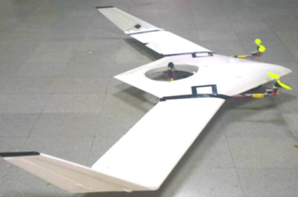
a) SkyTote introduced in [Reference Cord66] was a tail sitter mono thrust transitioning hybrid VTOL UAV. It was equipped with contra-rotating coaxial rotors installed at its nose. The torque generated by one rotor was canceled by the other. The vehicle was controlled by the cyclic and collective movement of the coaxial rotors as shown in Fig. 10. Estimated aerodynamic performance of the aircraft in cruise and hover modes were calculated and results were very encouraging when compared with fixed-wing or rotorcraft of the same class. Proof of the concept model of the aircraft was presented with details on its design features and fabrication processes. However, validation of the design by flight tests was not reported in the literature.
Figure 10. SkyTote aircraft, a mono thrust transitioning, tail-sitter hybrid VTOL UAV. Image adopted from reference [Reference Cord66], with permission.
-
b) The hybrid tail-sitter UAV was presented in [Reference Jung and Shim67]. It is composed of a ducted fan installed at its aft tail. The housing of the fan was equipped with control guide vanes installed downstream of the fan backwash. The deflection of the control vanes was utilised to realise the roll, pitch, and yaw control of the vehicle by thrust vectoring. Sweptback wings were installed to generate lift during the cruise flight. Forward canards were also employed to stabilise the aircraft in cruise mode. Successful transition from hover to cruise mode was achieved for this vehicle during experimental flights. Further discussion on its dynamic model and control laws is provided in a subsequent section.
-
c) Flexrotor [68] design composed of one main rotor with two blades installed at its nose for generation of thrust in hover and cruise flight. Two small rotors with a single blade were installed at each wingtip for stability and control augmentation. These small rotors also cancel the torque generated by the main rotor. A unique feature introduced in this aircraft was the retractable aft tail. That extends to form four-legged tail support for vertical takeoff and landing. When retracted, the tail transforms into conventional horizontal and vertical stabilisers for cruise flight. The aircraft exhibited remarkable hover and cruise efficiency and the ability to take off and land from a deck of a ship as shown in [70].
-
d) V-Bat [69] utilised shrouded coaxial rotors installed on a single shaft located at the aft tail of the aircraft. The guide vanes installed downstream of the coaxial rotor were employed to provide roll, pitch, and yaw control. It was equipped with a cylindrical fuselage and a wing of a high aspect ratio to generate lift in cruise flight. Its fully functional prototype and flight demonstrations can be seen in [71].
-
1) Flight dynamics modeling techniques and existing control laws for MTT hybrid UAVs

Table 5. Summary of technological development of mono thrust transitioning (mtt) hybrid VTOL UAVs

Six degrees of freedom mathematical models and control laws for MTT hybrid VTOL UAVs were addressed by various researchers [Reference Jung and Shim67, Reference Manouchehri, Hajkarami and Ahmadi72–Reference Frank, McGrew, Valenti, Levine and How77]. Hover control strategies for MTT hybrid VTOL UAVs were studied in [Reference Manouchehri, Hajkarami and Ahmadi72–Reference Bilodeau and Wong74]. Newton Euler’s representation of flight dynamics for an MTT ducted fan robot was performed in [Reference Manouchehri, Hajkarami and Ahmadi72]. The PID-based controllers were employed to stabilise the aircraft attitude in hover flight mode. Flight simulations in Simulink/MATLAB demonstrated the efficacy of the designed control laws. It was demonstrated in [Reference Matsumoto, Kita, Suzuki, Oosedo, Go, Hoshino, Konno and Uchiyama73] that for an MTT aircraft a quaternion-based feedback control algorithm could not provide robust hover control in the presence of strong environmental disturbances such as high-speed wind gusts. Instead, they proposed a novel control strategy implemented with PID controllers to achieve efficient hover control against large angular displacements from a neutral point. The proposed control strategy based on the resolved tilt-twist angle approach was validated by flight simulations and experimental results. Another research work [Reference Bilodeau and Wong74] implemented P and PI controllers in two different configurations of inner and outer loops on the MTT platform for its attitude stabilisation in hover flight. It was proved theoretically and experimentally that a combination of a PI controller in the inner loop with a P controller in the outer loop could provide better hover control with negligible overshoot errors. The control laws employed for a continuous ascent of hybrid tail-sitter UAV were presented in [Reference Jung and Shim67, Reference Jeong, Shim and Ananthkrishnan75]. Quaternion formulation was adapted instead of Euler angles to avoid singularity in the coordinate system. To achieve transition through continuous ascent trajectory the controller architecture is composed of dynamic inversion applied to flight path angle and velocity inputs fed to the PID-based thrust and attitude controllers that were linked via gain-scheduling. The proposed algorithm proved to be effective in achieving transition along the continuous ascent trajectories, thus avoiding the stall and tumble transition manoeuver. Quaternion-based flight dynamics model for V-Bat aircraft was presented in [Reference Argyle, Beard and Morris76]. Hierarchical control architecture built on PID loops was employed for hover, transition, and cruise control. A unique back transition control strategy was able to control the horizontal end position of the aircraft as demonstrated by the flight simulations. However, the developed controlling scheme did not address the altitude stabilisation during the transition manoeuver. The dynamic model for vertical takeoff, transition, cruise, back transition, and vertical landing of an MTT tail-sitter hybrid VTOL UAV was presented in [Reference Frank, McGrew, Valenti, Levine and How77]. Quaternion based global coordinate system was employed to keep track of the aircraft’s attitude without singularity issues even beyond ±90º pitch angle variations. The LQR controller for hover and PID controller for cruise flight was employed. Transition control logics were implemented with the trajectory flowing algorithms. Experimental flight tests showed that the autonomous flight control over the entire flight envelop was satisfactorily achieved.
-
2) MTT hybrid UAV designs
The mono thrust transitioning hybrid UAVs are simple to design and do not require any complex actuation systems for control surfaces or tilting mechanisms like other types of hybrid UAVs. However, practically their transition is difficult to achieve and mostly results in loss of altitude [70]. Highly sophisticated flight controllers are required to achieve a smooth transition between the flight modes. Moreover, the main rotor of the MTT hybrid UAVs is required to be designed carefully to provide the necessary thrust during all phases of flight. For MTT hybrid VTOL UAVs, the wings of a high aspect ratio with a large wingspan and small chord length are generally employed to make the aircraft less vulnerable to crosswinds during hover flight. These design features of the cylindrical narrow-body fuselage and slender wings greatly reduce the payload carrying capacity for MTT UAVs.
2.6 Collective thrust transitioning (CTT) hybrid VTOL UAVs
Collective thrust transitioning hybrid VTOL UAVs utilise multi-rotors to produce thrust for the complete mission profile of a tail-sitter platform. The transition between the flight modes is achieved by collective variation of the trust produced by the rotors combined with the deflection of control surfaces such as elevons or flaperons. Three representative designs of collective thrust transitioning hybrid VTOL UAVs are mentioned in Table 6. Two of the designs T-Wing [Reference Stone and Clarke78, Reference Stone, Anderson, Hutchison, Tsai, Gibbens and Wong79] and VD200 [80] have successfully demonstrated the CTT technology. Furthermore, WingtraOne [81] has been effectively commercialised for serial production.
-
a) A flight demonstrator vehicle of a T-Wing concept was presented in [Reference Stone and Clarke78, Reference Stone, Anderson, Hutchison, Tsai, Gibbens and Wong79]. It is composed of counter-rotating twin-propellers installed at mid-wing locations to generate thrust for all phases of flight. The control surfaces (rudders and ailerons) were positioned inside the propeller downwash to attain effective flight control during vertical and horizontal flight. Forward canards were also employed for longitudinal stability. Rotor blades’ pitch angle variations were utilised to give efficient cruise performance and to produce the thrust necessary for vertical flight. Mathematical modeling and control laws of T-Wing are further discussed in a subsequent section.
-
b) VD200 [80] was manufactured by Chengdu Aircraft Research and Design Institute (SARDI), China. It was a delta wing tail-sitter configuration, with two fixed pitch propellers, rotating in opposite directions. Both the propellers cancel each other’s torque and generate thrust for all flight modes. Elevons were employed for roll and pitch control. Two vertical stabilisers were utilised to stabilise the aircraft in cruise flight and to act as tail support for vertical takeoff and landing. A pair of flaperons placed downstream of the propeller wash were deflected to achieve transition between the modes. However, the results and success of the flight tests of VD200 were not reported in the literature.
-
c) WingtraOne [81] is a commercially produced CTT tail-sitter UAV. It is powered by two brushless DC motors and propellers. Across the flight, two control surfaces at the trailing edge of the wings operate to control the aircraft, under the influence of propeller slipstream as depicted in Fig. 11. A horizontal stabiliser and wingtip struts make the aft tail support of the aircraft. These simple yet efficient design features allow Wingtra One to operate at high flying speed for accurate mapping of vast fields in a limited time.
-
1) Flight dynamics modeling techniques and existing control laws for CTT hybrid UAVs
Table 6. Summary of technological development of collective thrust transitioning (ctt) hybrid VTOL UAVs


Figure 11. WingtraOne aircraft, a collective thrust transitioning hybrid VTOL UAV. Image adopted from reference [81], with permission.
Many researchers endeavored to explore the control laws for CTT hybrid VTOL UAVs. Hover control laws were studied in [Reference Wong, Guerrero, Lara and Lozano82–Reference VanderMey88], transition laws in [Reference Forshaw, Lappas and Briggs89–Reference Casau, Cabecinhas and Silvestre94] addressed control laws for full flight envelope.
Hover control of a model CTT hybrid aircraft was evaluated in [Reference Wong, Guerrero, Lara and Lozano82, Reference Guerrero, Lozano, Romero, Lara-Alabazares and Wong83]. A simplified mathematical model based on the Newton-Euler approach was derived for roll, pitch, and yaw motions in hover mode. A PD control algorithm was designed and its step-response for roll, pitch, and yaw control loops was simulated in MATLAB/Simulink. Derivatives of the aerodynamic coefficients for a PD controller were directly calculated from the Inertial Measurement Unit (IMU) during flight tests, instead of wind tunnel testing. Subsequent implementation of the controller on the hardware exhibited efficient control during hover flight tests. Euler-Lagrange based mathematical model of CTT hybrid VTOL aircraft was formulated for hover flight mode in [Reference Escareno, Salazar-Cruz and Lozano84, Reference Escareno, Salazar and Lozano85]. The aircraft is composed of ailerons and elevators control surfaces operating in the downwash of variable pitch propellers. Lyapunov function-based PD control laws were implemented in MATLAB/Simulink environment and subsequently on the experimental hardware to show the effective attitude stabilisation in hover mode. Newton-Euler based dynamic model was derived in [Reference Sanchez, Escareno, Garcia and Lozano86, Reference Escareno, Sanchez, Garcia and Lozano87] for hover flight of two CTT hybrid vehicles; the Twister comprising counter-rotating coaxial propellers on a single shaft and a bi-rotor T-Phoenix. Elevator and rudder control inputs were given to a Lyapunov function-based controller to stabilise the aircraft in hover mode. MATLAB simulations and in-flight experiments validated the designed control laws. In another academic research work on experimental CTT hybrid vehicles [Reference VanderMey88], its flight dynamics model and control laws were produced. For controlling the non-linear dynamics of the vehicle during takeoff, non-liner dynamic inversion was employed. A nested PID controller was used for altitude and attitude stabiliation in hover flight. To tackle the transient response of the controller during the transition phase, a controller switching algorithm was proposed to achieve a smooth transition. Hover control was successfully displayed by flight testing of the experimental vehicle. Cruise flight control was not addressed in this work.
The research work presented in [Reference Forshaw, Lappas and Briggs89] focused exclusively on controlling the transition phase of flight. The model aircraft was equipped with twin-propellers at wingtips and elevon control surfaces. PID controllers were designed based on a six-degree of freedom mathematical model. Quaternion-based attitude and altitude controllers for vertical flight segment of transition and altitude, path angle, and speed controller for the horizontal segment of the transition phase were developed. The transition coordinator was implemented to simulate the control strategies. However, experimental verification of said control laws was not found in the literature. Six degrees of freedom dynamic model of T-Wing tail-sitter vehicle was formulated in [Reference Stone and Clarke78, Reference Stone, Anderson, Hutchison, Tsai, Gibbens and Wong79, Reference Stone95]. Control strategies were defined to reduce the altitude loss in hover to cruise transition and altitude gain in cruise to hover transition in comparison with aircraft altitude during a practical un-augmented transition maneuver. LQR based controllers were employed for hover control. Classical root locus Single-Input Single-Output (SISO) controllers were applied for cruise control. Flight mode transition was achieved by the classical controllers implemented with the guidance algorithms. Flight simulations for full envelope were performed in Simulink and encouraging results were obtained. Afterward, an autonomous vertical flight of the experimental vehicle was also achieved. However, autonomous flight over the entire flight envelope was not reported in the literature.
To achieve robust control for CTT hybrid VTOL UAVs over the entire flight envelope, a quaternion formulation was used to derive non-linear mathematical models in [Reference Knoebel and McLain90–Reference Osborne92]. Back-stepping control laws were formulated in [Reference Knoebel and McLain90], Dynamic inversion method was used in [Reference Kohno and Uchiyama91] whereas simple, feedback linearisation, and adaptive controllers were developed in [Reference Osborne92]. Results of flight simulations and experimental tests on hardware were also reported in [Reference Knoebel and McLain90–Reference Osborne92]. LQR and gain scheduling techniques were adopted in [Reference Casau, Cabecinhas and Silvestre93, Reference Casau, Cabecinhas and Silvestre94] to develop hybrid control strategies for the autonomous transition of model aircraft. Mathematical modeling and simulation results were presented but flight testing results were not reported in this work [Reference Casau, Cabecinhas and Silvestre93, Reference Casau, Cabecinhas and Silvestre94].
-
2) CTT hybrid UAV designs
Collective thrust transitioning hybrid VTOL UAVs exhibit simple designs without the need for any extra actuators. They can execute energy-efficient high-speed forward flights. Various design options for wing geometric shapes can be employed for CTT hybrid UAVs. The use of multiple rotors gives actuation and control freedom to collective thrust transitioning UAVs in comparison to mono thrust transitioning designs. However, the attitude and altitude control of these vehicles in hover flight are difficult to attain and thus require high fidelity dynamic model-based robust controllers. These aircraft are difficult to control in the presence of strong crosswinds. Furthermore, high-strength tail landing supports are required to sustain the vertical landings. They have been sufficiently studied in academia and industry and considerable design and control work is available in the literature. But still, CTT hybrid UAV development is in its early stages, as only three of the successful designs have been developed so far as mentioned in Table 6.
2.7 Differential thrust transitioning (DTT) hybrid VTOL UAVs
The most recently introduced and rapidly growing configuration of hybrid VTOL UAVs is the differential thrust transitioning tail-sitter design. They comprise four rotors in either ‘x’ configuration [Reference Hochstenbach, Notteboom, Theys and De Schutter96–98] or ‘+’ configuration [99–101] to power the aircraft in all phases of flight. Their hover control methodology is much like a quadcopter. Delta wing [98, 101], swept-forward [99], or swept-back [Reference Hochstenbach, Notteboom, Theys and De Schutter96, 97, 100] wings were employed in various designs mentioned in Table 7. The rotors are installed at the upper and lower side of the wing plane. The differential thrust produced by these rotors is used to attain pitch-up or pitch-down angular variations during flight mode transition. After the mid-air flip of the airframe during the transition phase, all rotors produce forward thrust for cruise flight and wings start to act as a primary source of lift. Wing mounted elevons are employed for roll and pitch control of the aircraft in flying wing configuration during cruise flight. Yaw control in cruise is achieved either by the rudder or differential thrust of the rotors installed at the wingtips.
-
a) VertiKUL aircraft, designed for parcel delivery applications was introduced in [Reference Hochstenbach, Notteboom, Theys and De Schutter96]. It is composed of four rotors attached at the upper and lower side of a swept-back wing in ‘x’ configuration, like a quadrotor rotorcraft. This vehicle was controlled by the differential thrust of the propellers in hover, transition, and cruise mode, and no control surface or actuators were employed, refer to Fig. 12. This on one hand resulted in design simplification and cost reduction, but on the other hand, raised the requirement for sophisticated flight control mechanisms. Control strategies of VertiKUL are discussed in the subsequent section. Successful technology demonstration of VertiKUL was achieved in [Reference Hochstenbach, Notteboom, Theys and De Schutter96].
-
b) Quadshot design [97] was equipped with four rotors, two inboard rotors at one side of the wing, and two outboard rotors at the other side. Rotors produce lift for vertical takeoff and thrust for cruise flight. Elevons provide roll and pitch control augmentation. Swept-back wing produced lift in cruise flight. Rotor mountings were extended to produce the tail support for vertical takeoff and landing. Winglets were also attached at each wingtip for directional stability.
-
c) Heliwing [99] was the technology demonstrator vehicle produced by Boeing. It utilised two pairs of counter-rotating propellers to generate thrust over the entire flight envelope. The transition was achieved by differential thrust of the rotors. Rudders and elevons were employed for pitch, yaw, and roll control. Only one demonstrator vehicle was produced which got crashed on its sixth flight. Afterward, Boeing did not pursue the project further.
-
d) A fully functional prototype of Google’s Project Wing vehicle was demonstrated in [98]. It was designed for package delivery applications. Two inboard rotors on one side of the delta wing and two outboard rotors on the other side were employed to generate thrust in cruise and lift in hover mode. The differential thrust of the inboard and outboard rotors was employed to achieve a successful transition between the modes. Elevons provide roll and pitch control in cruise. This project is still underway, new technologies are being tested.
-
e) ATMOS UAV was unveiled in [100], this tail-sitter aircraft was developed to achieve efficient hovering smooth transition and high-speed cruise. Two rotors were installed at each wingtip and two rotors at the vertical tail-mounted struts, this formed a ‘+’ configuration of rotors placement (refer to Fig. 13). Struts extend backward to form four-point tail support for vertical takeoff and landing. Streamline body fuselage carried the electronics and payload.
Table 7. Summary of technological development of differential thrust transitioning (dtt) hybrid VTOL UAVs.
Figure 12. VertiKUL aircraft, a differential thrust transitioning hybrid VTOL UAV, in hover flight. Image adopted from reference [Reference Hochstenbach, Notteboom, Theys and De Schutter96], with permission.
Figure 13. ATMOS UAV, a differential thrust transitioning tail-sitter hybrid VTOL UAV. Image adopted from reference [102], with permission.
-
f) X Plus One is another commercial design introduced in [101]. It is composed of two rotors at each wingtip and two at the tips of the vertical tail, forming the ‘+’ configuration. Delta wing with winglets was employed in this design, refer to Fig. 14. Flight control for roll, pitch, and yaw is achieved by differential thrust of the rotors, in all flight modes. No actuators or control surfaces were employed in this design. This makes the design simpler and cost-efficient. ATMOS UAV and X Plus One designs have been introduced as successful products in the commercial market. However, their design, analysis, dynamic modeling, and control laws are not available in any form in the literature.
Figure 14. X Plus One, a differential thrust transitioning tail-sitter hybrid VTOL UAV. Image adopted from reference [101], with permission.
-
1) Flight dynamics modeling techniques and existing control laws for DTT hybrid UAVs


Tail-sitter Differential Thrust Transitioning (DTT) technology is at its early development stages and very little systematic research in terms of dynamic modeling and control laws is available in the literature. Only one research work that can be regarded as a benchmark was presented for VertiKUL UAV in [Reference Hochstenbach, Notteboom, Theys and De Schutter96, Reference Theys, De Vos and De Schutter103]. Quaternion formulation was employed to formulate six degrees of freedom dynamic model. PID controllers were employed for altitude and attitude stabilisation of vehicles in all flight modes. For heading control, a separate controller was implemented. Flight testing validated the proposed control laws for the transition flight of VertiKUL. However, during dynamic modeling, only the related aerodynamic effects were studied but the detailed Computational Fluid Dynamic (CFD) analysis or Wind Tunnel Testing were not carried out.
-
2) DTT hybrid UAV designs
In comparison to mono and collective thrust transitioning hybrid VTOL UAVs the differential thrust transitioning vehicles exhibit a high thrust to weight ratio in cruise mode on account of a greater number of thrust-generating rotors. DTT vehicles also possess high payload carrying capacity than the MTT and CTT vehicles. The simple design of DTT UAVs eliminates the need for any extra actuators or control surfaces thus resulting in a clean design and easy fabrication. They offer good stability and controllability in hover and cruise. Various options for wing geometry can be explored for DTT vehicles such as delta wing, swept-forward, or swept-back wings. These vehicles exhibit easy takeoff and landing. Currently, DTT hybrid UAVs are at the forefront of academic and industrial research. Certain drawbacks associated with DTT configuration are the control authority degradation in the presence of strong crosswinds and the requirement of considerably higher differential thrust to achieve transition by the midair flip of the airframe.
3.0 Recent developments and ongoing research work on hybrid vtol UAVs
Summary of ongoing research projects on hybrid VTOL UAVs is presented in Table 8. Wagter et al. [Reference De Wagter, Remes, Ruisink, Van Tienen and Van der Horst104] presented a tandem wing configuration hybrid UAV with six propellers installed on each wing (Fig. 15). This concept is currently being developed at the Delft University of Technology to study the alternatives of electrical batteries to power hybrid VTOL UAVs, for enhanced range and endurance. It utilises a hydrogen fuel cell and pressure tank to power the propellers. All 12 propellers remain operational during hover and VTOL. Whereas only the wingtip propellers produce thrust during the forward flight. Other rotor blades are retracted during cruise mode to reduce drag. The concept has only been flown with the electrical batteries, flight with hydrogen fuel cells is awaited.
Table 8. Summary of ongoing projects on hybrid VTOL UAVs

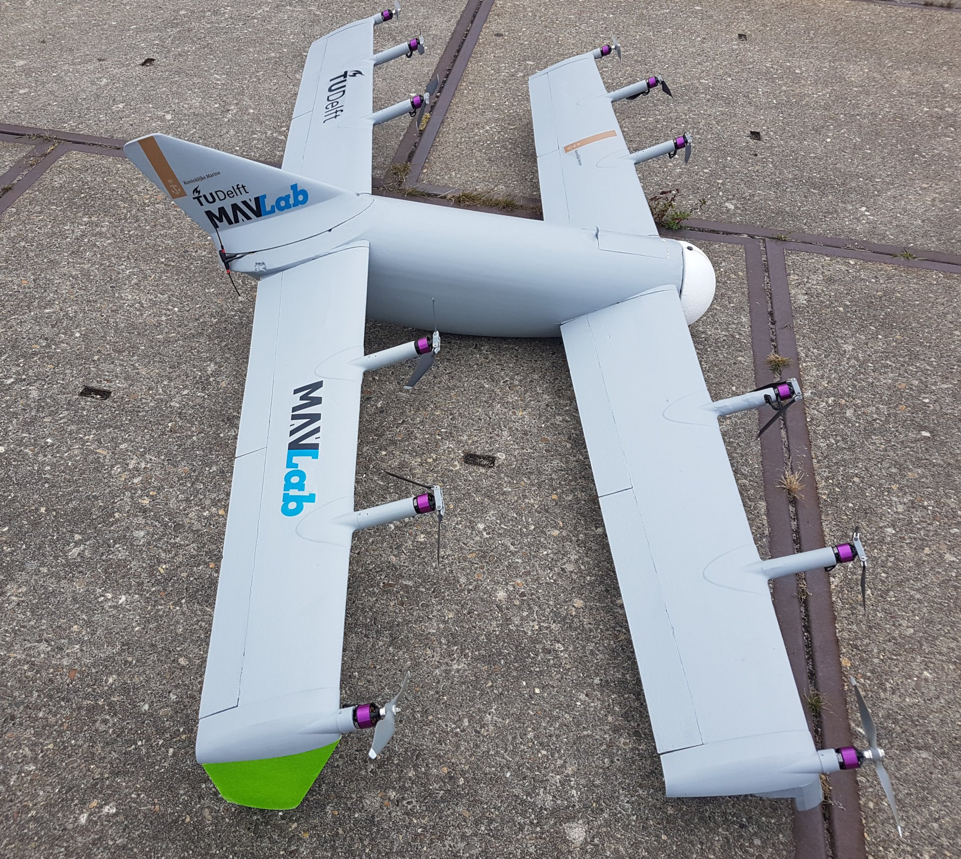
Figure 15. NederDrone2 aircraft, a hybrid VTOL UAV being manufactured by Delft University of Technology. Image adopted from reference [Reference De Wagter, Remes, Ruisink, Van Tienen and Van der Horst104], with permission.
Lucena et al. [Reference Rao111] are working on a double hybrid tail-sitter UAV configuration at the Federal University of Rio Grande do Norte (UFRN), Brazil. This concept employs two wing mounted electric propellers for hover and VTOL. Whereas a combustion engine is installed to power a pusher rotor at the aft tail to generate thrust for the forward flight. This configuration is anticipated to give high energy efficiency and enhanced area coverage.
Li et al. [Reference Tomaszewska112] are working on a quad-rotor tail-sitter design to study the transition between the flight modes at the Hong Kong Polytechnic University (Fig. 16). Trajectory optimisation techniques are being employed, on this differential thrust transitioning hybrid UAV. Loss of altitude during transition is being addressed by the implementation of non-linear controllers. SuperVolo [105] is a dual system hybrid VTOL UAV under development at GE Aviation, USA (Fig. 17). It utilises an onboard gasoline fueled engine to charge the batteries during flight. This concept can provide enhanced range and endurance with quick turnarounds.

Figure 16. Quad-rotor Tail-sitter hybrid VTOL UAV in hover flight mode. Image adopted from reference [Reference Tomaszewska112], with permission.

Figure 17. SuperVolvo hybrid VTOL UAV, being developed by GE Aviation, USA. Image adopted from reference [105], with permission.
Detailed study of various types of hybrid VTOL UAVs revealed that each type presents its own merits and demerits. In the section 4, the authors have used Multi Attribute Decision Making techniques to select the most suitable configuration for the design and development of a VTOL hybrid UAV. Critical design and performance parameters of representative aircraft from each type of design configurations (discussed in section 2) were analysed. Differential Thrust Transitioning UAV design outperformed the other design configurations when evaluated in terms of range, endurance, payload capacity, cruise speed, stability, design complexities and level of autonomy, etc. Therefore, the authors have selected Differential Thrust Transitioning design configuration to design a hybrid VTOL UAV, in section 5. The authors introduced their designed aircraft and presented its specifications in section 6. Details pertaining to its aerodynamic analysis, mathematical modeling, flight simulations, and control laws are not included in the scope of this review and will be provided in the subsequent publication.
4.0 Design configuration selection problem
After studying all the design configurations of hybrid VTOL UAVs, it may be envisaged that the selection of UAV design configuration is a complex decision-making problem as each configuration exhibits distinct merits and demerits. It becomes very difficult for a decision-maker to select a particular configuration based on varying attributes. This calls for a systematic and scientific selection approach that is independent of the selector’s judgement. To address this issue Multi-Attribute Decision Making (MADM) techniques were adapted to select the most suitable design configuration in the presence of multiple conflicting criteria [Reference Mohanty, Mahapatra and Mohanty106–Reference Yeh113]. Multi-Attribute Decision Making allows the decision maker to solve a problem involving selection from the finite set of alternatives. These methods provide the mechanism for processing the information about the alternatives to arrive at the best choice. The alternatives are evaluated based on inter- and intra-attribute comparisons. The decision matrix of MADM problem typically comprises alternatives (A i ), attributes (B j ), weights of attributes (w j ), and measures of performance of each alternative with respect to attributes (x ij ) (refer to Table 9).
Table 9. Decision matrix for a typical madm problem

To formulate our decision-making problem one representative UAV of the same class (electric powered) was chosen from each category of hybrid VTOL UAVs discussed in the paper. The decision matrix was formed, as shown in Table 10. Rotary-wing design was not considered as no fully functional prototype for this class was developed and mono thrust transitioning designs were not considered as all four available designs are gasoline-powered. The leftmost columns of Table 10 depict the alternative design configurations and their representative UAVs written against each. These alternatives were evaluated based on four objectives and four subjective attributes. These attributes correspond to the most critical design and performance parameters for hybrid Unmanned Aerial Vehicles.
Table 10. Decision matrix for hybrid VTOL UAV configuration selection problem

Objective attributes are those parameters for which absolute value can be assigned. Objective attributes in the presented problem are range, endurance, payload to Maximum Takeoff Weight (MTOW) ratio, and cruising speed. Whereas subjective attributes are performance and stability, ease of fabrication, level of autonomy, and deadweight during cruise flight. For subjective attributes, no numeric value can be assigned whereas they are expressed in linguistic terms. The justification for the selection of attributes to evaluate the alternatives, in a hybrid UAV selection problem is provided as follows.
The actual value of each objective attribute was taken from the literature. Each subjective attribute was expressed via a linguistic variable on the scale of Very Low (VL) to Very High (VH) based on the literature survey. Figure 18 shows the five-point scale of the linguistic variables and their triangular membership function with the fuzzy variables.

After a literature survey of the Multi-Attribute Decision-Making Methods [Reference Mohanty, Mahapatra and Mohanty106–Reference Yeh113], the Fuzzy Technique of Ordered Preference by Similarity to Ideal Solution (TOPSIS) was found to be the most suitable technique for our decision making problem, because it is a powerful technique that can cater to both objective and subjective attributes alike. In the Fuzzy TOPSIS method, the chosen alternative need to have the shortest Euclidean distance from a positive ideal solution at the same time it needs to be farthest away from a negative ideal solution. The triangular membership of each linguistic variable with a fuzzy variable is shown in Table 10. Table 10 represents the alternatives, attributes and measures of performance of each alternative with respect to attribute
 ${x_{ij}}$
, thus forming the decision matrix of the MADM problem.
${x_{ij}}$
, thus forming the decision matrix of the MADM problem.
The linguistic variables need to be converted into fuzzy variables to enter the decision-making process. The crisp score of fuzzy numbers shown in Table 11 was calculated by using the following relations from reference [Reference Chen109]. The maximum (
 ${\mu _{max}}$
) and minimum (
${\mu _{max}}$
) and minimum (
 ${\mu _{min}}){\rm{\;}}$
score of each fuzzy number is calculated by Equation 1. Then the left (
${\mu _{min}}){\rm{\;}}$
score of each fuzzy number is calculated by Equation 1. Then the left (
 ${\mu _L}){\rm{\;}}$
and right (
${\mu _L}){\rm{\;}}$
and right (
 ${\mu _R})$
score of fuzzy numbers were obtained from Equation 2 and finally, the total score
${\mu _R})$
score of fuzzy numbers were obtained from Equation 2 and finally, the total score
 $({\mu _T}){\rm{\;}}$
of each fuzzy number is incorporated in a decision-making problem.
$({\mu _T}){\rm{\;}}$
of each fuzzy number is incorporated in a decision-making problem.
 \begin{align}\begin{array}{*{20}{c}}{{\mu _{max}}\left( x \right) = \left\{ {\begin{array}{*{20}{c}}{x,0 \le x \le 1}\\[5pt] {0,\;{\rm otherwise}\;}\end{array}} \right\}}\\[18pt]{{\mu _{min}}\left( x \right) = \left\{ {\begin{array}{*{20}{c}}{1 - x,0 \le x \le 1}\\[5pt]{0,\;{\rm otherwise}\;}\end{array}} \right\}}\end{array}\end{align}
 \begin{align*}{\mu _L}\left( {{M_i}} \right) = sup\!\left[ {{\mu _{min}}\left( x \right){\rm{\Delta }}{\mu _{Mi}}\left( x \right)} \right]\end{align*}
 \begin{align*}{\mu _R}\left( {{M_i}} \right) = sup\!\left[ {{\mu _{max}}\left( x \right){\rm{\Delta }}{\mu _{Mi}}\left( x \right)} \right]\end{align*}
 \begin{align}{\mu _T}\!\left( {{M_i}} \right) = \left[ {{\mu _R}\left( {{M_i}} \right) + 1 - {\mu _L}\left( {{M_i}} \right)} \right]/2\end{align}

Figure 18. Triangular membership function of linguistic variables with fuzzy variables on a five-point scale.
Table 11. Decision matrix after calculating crisp score of fuzzy variables

After obtaining the crisp score of fuzzy numbers, the decision matrix shown in Table 11 contains
 ${x_{ij}}$
terms, which shows the rating of each alternative ‘i’ with respect to each attribute ‘j’. The next step is to normalise the decision matrix by using the following relation.
${x_{ij}}$
terms, which shows the rating of each alternative ‘i’ with respect to each attribute ‘j’. The next step is to normalise the decision matrix by using the following relation.
 \begin{align}x_{ij}^{\rm{*}} = {x_{ij}}/{\left( {{x_{ij}}} \right)_{max}}\end{align}
Normalised crisp ratings of alternatives
 $x_{ij}^*$
with respect to the attributes are obtained in Table 12, the next step is to define the objective weight of each attribute. Statistical variance gives the measure of the dispersion of the data hence it was used to calculate the objective weights of attributes. The variance
$x_{ij}^*$
with respect to the attributes are obtained in Table 12, the next step is to define the objective weight of each attribute. Statistical variance gives the measure of the dispersion of the data hence it was used to calculate the objective weights of attributes. The variance
 ${v_j}\;$
was calculated by Equation 4, and objective weights
${v_j}\;$
was calculated by Equation 4, and objective weights
 $w_j^o\;$
were evaluated by Equation 5. Calculated values of objective weights of attributes are shown in Table 13.
$w_j^o\;$
were evaluated by Equation 5. Calculated values of objective weights of attributes are shown in Table 13.
 \begin{align}{v_j} = \left( {1/n} \right)\mathop \sum\nolimits_{i = 1}^n {\left( {x_{ij}^* - {{\left( {x_{ij}^*} \right)}_{{\rm{mean}}}}} \right)^2}\end{align}
 \begin{align}w_j^o = {v_i}/\mathop \sum\nolimits_{j = 1}^m {v_j}\end{align}
For the application of the Fuzzy TOPSIS method, the normalised decision matrix was evaluated by Equation 6. Table 14 shows the normalised decision matrix for the selection problem.
 \begin{align}x_{ij}^* = {x_{ij}}/{\left[ {\mathop \sum\nolimits_{j = 1}^m\quad x_{ij}^2} \right]^{1/2}}\end{align}
Table 12. Normalised crisp ratings of alternatives with respect to attributes

Table 13. Calculated objective weights of attributes

Table 14. Normalised decision matrix for the selection problem

The weighted normalised decision matrix with
 ${y_{ij}}$
terms, shown in Table 15, can be calculated by using Equation 7. Where objective weight of each attribute
${y_{ij}}$
terms, shown in Table 15, can be calculated by using Equation 7. Where objective weight of each attribute
 $w_j^o$
is multiplied with the normalised ratting values
$w_j^o$
is multiplied with the normalised ratting values
 $x_{ij}^*\;$
of each alternative with respect to attributes, obtained earlier in Table 14.
$x_{ij}^*\;$
of each alternative with respect to attributes, obtained earlier in Table 14.
 \begin{align}{y_{ij}} = w_{}^o \times x_{ij}^*\;\end{align}
Table 15. Weighted normalised matrix for alternatives

The positive ideal best
 ${A^ + }$
and negative ideal worst
${A^ + }$
and negative ideal worst
 ${A^ - }$
solutions were obtained from Equations 8 and 9 respectively and are shown in Table 16.
${A^ - }$
solutions were obtained from Equations 8 and 9 respectively and are shown in Table 16.
 \begin{align} {A^ + } & = \left\{ {y_1^ + , \ldots \ldots \ldots .y_m^ + } \right\} \nonumber \\ & = \left\{ {\left( {\mathop {max}\limits_i {y_{ij}}/j \in {J^I}} \right),\left( {\mathop {min}\limits_i {y_{ij}}/j \in {J^{II}}} \right)} \right\} \end{align}
 \begin{align} {A^ - } & = \left\{ {y_1^ - , \ldots \ldots \ldots .y_m^ - } \right\} \nonumber \\ &= \left\{ {\left( {\mathop {min}\limits_i {y_{ij}}/j \in {J^I}} \right),\left( {\mathop {max}\limits_i {y_{ij}}/j \in {J^{II}}} \right)} \right\} \end{align}
Table 16. Positive ideal best and negative ideal worst solutions of decision-making problem

Where
 ${J^I}$
is a set of beneficial attributes and
${J^I}$
is a set of beneficial attributes and
 ${J^{II}}$
is a set of non-beneficial attributes. In the presented decision-making problem all the attributes are beneficial attributes
${J^{II}}$
is a set of non-beneficial attributes. In the presented decision-making problem all the attributes are beneficial attributes
 ${J^I}$
except for the dead weight during the cruise flight, which is a non-beneficial attribute
${J^I}$
except for the dead weight during the cruise flight, which is a non-beneficial attribute
 ${J^{II}}$
. Higher values of
${J^{II}}$
. Higher values of
 ${J^I}$
and lower values of
${J^I}$
and lower values of
 ${J^{II}}$
are desirable. Hence the maxima of the
${J^{II}}$
are desirable. Hence the maxima of the
 ${J^I}$
and minima of
${J^I}$
and minima of
 ${J^{II}}$
form the positive ideal best solution
${J^{II}}$
form the positive ideal best solution
 ${A^ + }$
. Similarly, the minima of
${A^ + }$
. Similarly, the minima of
 ${J^I}$
and the maxima of
${J^I}$
and the maxima of
 ${J^{II}}$
forms the negative ideal worst solution
${J^{II}}$
forms the negative ideal worst solution
 ${A^ - }$
.
${A^ - }$
.
Euclidean distance of each alternative from positive ideal best solution gives the positive separation measure
 $D_i^ + ,\;$
calculated by Equation 10. Euclidean distance of each alternative from negative ideal worst solutions gives the negative separation measure
$D_i^ + ,\;$
calculated by Equation 10. Euclidean distance of each alternative from negative ideal worst solutions gives the negative separation measure
 $D_i^ - ,$
calculated by Equation 11. The calculated values of
$D_i^ - ,$
calculated by Equation 11. The calculated values of
 $D_i^ + $
and
$D_i^ + $
and
 $D_i^ - $
are shown in Table 17.
$D_i^ - $
are shown in Table 17.
 \begin{align}D_i^ + = \sqrt {\mathop \sum \limits_{j = 1}^m {{\left( {{y_{ij}} - y_j^ + } \right)}^2},i = 1,2 \ldots \ldots \ldots .I} \end{align}
 \begin{align}D_i^ - = \sqrt {\mathop \sum \limits_{ = 1}^m {{\left( {{y_{ij}} - y_j^ - } \right)}^2},i = 1,2 \ldots \ldots \ldots .I} \end{align}
Table 17. Ranking of alternatives

Finally, the overall performance score
 $C_i^ + \;$
of each alternative was calculated by Equation 12.
$C_i^ + \;$
of each alternative was calculated by Equation 12.
 \begin{align}C_i^ + = \frac{{D_i^ - }}{{D_i^ + + D_i^ - }},i = 1,2 \ldots \ldots I\end{align}
Based on the overall performance score, Table 17 shows the ranking of alternatives. As a result of the application of multi-attribute decision-making methods to our decision-making problem, the differential thrust transitioning hybrid VTOL UAV came out to be the best alternative, when evaluated in terms of critical design and performance parameters. The adopted methodology can be applied to any selection problem, but care must be taken while defining the attributes based on which the alternatives are evaluated. This definition of attributes varies in every selection problem and strongly influences the result of the MADM problem.
5.0 Selection of platform
After analysing hybrid VTOL UAVs design configurations in detail, authors conclude that when evaluated in a competitive environment based on varying attributes such as range, flight time, payload capacity, cruise speed, performance, stability, design complexities and level of autonomy, the differential thrust transitioning hybrid UAVs can outperform all other types of hybrid UAVs. DTT hybrid UAVs exhibits simpler designs, that can be manufactured at a low cost. They surpass the convertiplanes in terms of aerodynamic performance and energy efficiency. However, the transition of DTT aircraft is achieved practically in a stall and tumble maneuver making the aircraft vulnerable to a crash. The advantages of this technology can be fully exploited if the transition is achieved within the specified transition corridors by the implementation of high-fidelity stability and control augmentation systems. The authors suggest that the transition of DTT hybrid UAVs should be studied extensively in future research. In-depth aerodynamic analysis, high-reliability dynamic modeling, and robust flight controllers can lead to realising a smooth transition for DTT tail-sitter hybrid VTOL UAVs.
6.0 Proposed design of hybrid VTOL UAV
An innovative conceptual design of differential thrust transitioning tail sitter platform, designed by the authors, is shown in Fig. 19. This UAV comprises the swept-back wing with high lift producing cambered aerofoil. The aerodynamic shaped fuselage is blended with the wings to reduce drag. The electrical bay and payload compartment are stationed in the nose section of the fuselage, to keep the center of gravity ahead of the neutral point for longitudinal static stability. Four vertical fins comprising the symmetric aerofoil are attached to the wings at upper and lower sides. A carbon fiber boom is attached at the tip of each vertical fin. Vertical fins also provide directional stability. A pair of brushless DC motors and propellers are attached at the front end of each boom. Four motors and propellers are employed to generate thrust in all phases of flight, refer to Fig. 19. The aft end of the carbon fiber booms forms the tail support for vertical takeoff and landing.

Figure 19. Design of a VTOL hybrid UAV, being developed by the authors.

Table 18. Summary of modeling and control research work on hybrid VTOL UAVs

The thrust produced by all four rotors will support the weight of the aircraft in hover and VTOL. For the transition from VTOL to the cruise flight, the thrust of the two rotors attached on the upper side of the wing will be increased and the thrust of the two rotors attached on the lower side of the wing will be decreased. This differential thrust will generate a moment to rotate the aircraft about its lateral axis, for flight mode transition. When the aircraft speed reaches above the stall velocity, the transition phase of flight will culminate and all four rotors will start to produce thrust for forward flight and lift will be generated by the wings to support the weight of the aircraft. While transitioning back from a cruise to VTOL the reverse differential thrust will be applied, to rotate the aircraft about its lateral axis, so that it can land back on its tail. For back transition, the thrust produced by the two lower rotors will be increased and the thrust produced by the two upper rotors will be decreased. This configuration is expected to have high endurance and range in comparison to the rotorcrafts of the same class. Because, for this design, the lift generated by the wings in the cruise mode will support the weight of the aircraft, and rotors will be operated at considerably low power settings to generate forward thrust. This configuration is thus expected to complete the mission at the expense of significantly lower energy than the rotorcraft UAVs.
This simple yet efficient design provides low cost and ease of fabrication, as a smaller number of actuators are involved in the design. However, its control strategies are to be separately defined and implemented for hover, transition, and cruise flight modes. This design is currently being analysed and fabricated by the authors.
7.0 Conclusions
Enormous military and commercial applications of autonomous VTOL hybrid UAVs make them an attractive choice of aviators around the globe. They have the potential to revolutionise the operations in the sectors of intelligence, surveillance, reconnaissance, data collection, spying, surveying, mapping, package delivery, inspection, and drone swarming applications. Hybrid VTOL UAVs are expected to dominate the drone market by outperforming the conventional fixed-wing and rotorcraft UAVs. The benefits of hybrid VTOL technology can be fully achieved if future research is focused on the critical evaluation of the hybrid UAV designs in the disciplines of aerodynamics, propulsion, structures, materials, flight stability and controls. Moreover, the transition between the flight modes is the single most important domain that needs to be studied extensively to take advantage of the dividends of this innovative technology (Table 18).


