Introduction
Shock initiation by a laser-driven flyer is an initiation technology that laser ablates flyer film to drive remaining part on the surface of explosive. This technology provides a superior security and reliability for missile, spacecraft, and many other systems in the complex electromagnetic environment in modern war (Chen et al., Reference Chen, Wu, Shen, Ye and Hu2015; Shu et al., Reference Shu, Huang, Ye, Jia, Wu and Fu2017). Furthermore, laser-driven flyer detonator can respond virtually instantaneous. The delay time of explosive initiated by laser flyer decrease to approximate 1 µs, comparing delay time of traditional electric initiating in millisecond or microsecond level. Laser flyer initiation technology can provide synchronism of multipoint initiating, which orientate the development of the modern initiating explosive device. Sub-micron particles hexanitrostilbene (HNS-IV) is highly sensitive to shock initiation but insensitive to other forms of initiation, such as thermal and friction stimulation (Zeng et al., Reference Zeng, Li, Li and Wu2016). With the advantage of short-duration shock waves detonation of explosives (Setchell, Reference Setchell1984; Dean, Reference Dean2017), fine particles of HNS-IV are widely used in laser-driven flyer detonator.
At present, the research of laser-driven flyer plates technology has been developed from single to multilayer flyer plates with the purpose of improving the completeness and shock pressure of flyer plates (Paisley et al., Reference Paisley, Luo, Greenfield and Koskelo2008; Chen et al., Reference Chen, Wang and Wu2013a; Shaw et al., Reference Shaw, Williams, Dreizin and Dlott2014; Dean et al., Reference Dean, De Lucia and Gottfried2016, Reference Dean, De Lucia and Gottfried2017). Absorption/ablation layer of nano-film materials have attracted great interest in many researchers which offer potential advantages over conventional laser-driven flyer plates including increased laser pulse energy coupling efficiency by providing lower laser-induced energy, higher velocity of flyer plates, and tremendous output energy magnitude (Hatt & Waschl, Reference Hatt and Waschl1996; Greenaway et al., Reference Greenaway, Proud, Field and Goveas2003; Brierley et al., Reference Brierley, Williamson and Vine2012; Yu et al., Reference Yu, Fedotov, Baek and Yoh2014).
The technology of laser-driven flyer shock initiation with transparent substrate is a considerably mature, and shock pressure of flyer plate has an important influence on the initiation of explosive (Chen et al., Reference Chen, Wu, Shen, Ye and Hu2015) as well as the granularity of explosive particles also influence on the performance of the detonator initiation (Labaste et al., Reference Labaste, Doucet and Joubert1996; Greenaway et al., Reference Greenaway, Proud, Field and Goveas2003; Pahl et al., Reference Pahl, Muenchausen, Welle, Tappan, Palmer and Peiris2006; Bowden, Reference Bowden2015; Zeng et al., Reference Zeng, Li, Li and Wu2016). In order to investigate the influence of various absorption/ablation materials in the multilayer flyer energy conversion elements (MFECEs), carbon/aluminum (C/Al), magnesium/aluminum (Mg/Al), and aluminum (Al) were integrated into MFECEs as the laser ablative layer using magnetron sputtering. We then systematically investigated the initiation performance of the MFECEs under nanosecond laser pulse conditions and analyzed the influence of layered structure to flyer plate initiation on HNS-IV comparing with single-layer Al flyer plate. Additionally, the shear fracture morphologies of laser-driven flyer plates were analyzed using laser scanning confocal microscope (LSCM).
Experimental section
The apparatus for laser-driven flyer initiation is showed in Figure 1(a). Solid pulsed Q-switched Nd:YAG (6.5 ns, 1064 nm, 350 mJ) output a Gaussian laser pulse through a convex lens (focal length 12 cm) and a K9 glass substrate (the laser spot diameter is 0.6 mm after focusing), and focus on the interface between ablation layer and glass substrate. The flyer plate, work as energy transfer element, absorbs laser pulse energy and vaporize. A fraction of the metal is ablated, which expand and develop a shock wave at the interface between ablation layer and glass substrate. The flyer plate is driven and sheared by a shorter (Φ0.7 × 0.6 mm) barrel to receive a high velocity, when the shock wave achieve free surface. The flyer plate flied through barrel and strike and initiate HNS-IV. Lead plate was used to check if detonation is complete. By using a photonic Doppler velocimetry (PDV) we measure the velocity of the flyer plates. The energy of pulse laser was recorded with a laser energy meter. Under each identical condition, three samples of each kind of flyer plate were initiated, and then the results were averaged. Structural microscopic of four kinds of flyer plates characterization were performed using field emission scanning electron microscopy. The composition of flyer shear zone and non-initiation’ HNS-IV grains were determined using an energy dispersive spectrometer (EDS, NORAN System SIX). The surface reflectivity measurements of the Al, C/Al and Mg/Al layers were performed using reflectivity (AvaSpec-NIR256-1.7). When the laser light is incident on the surface of flyer plate, the reflected light of laser will be reflected in the integrating sphere for many times. That makes the laser light intensity of every point of the sphere internal surface the same and uniform distribution. The reflected light of the laser is measured by the spectrometer and calculated out the reflectivity synchronized by the computer software. Figure 1(b) shows the apparatus of LSCM (OLS3100, OLYMPUS).
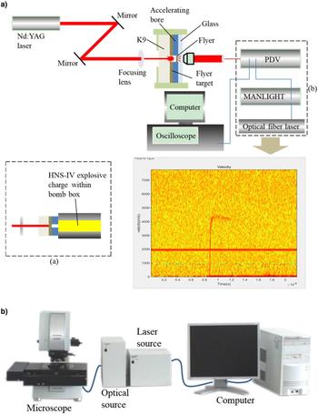
Fig. 1. (a) Schematic diagram of HNS-IV initiated by laser-driven flyer plate (a) shock initiation device; (b) PDV. (b) Schematic diagram of the laser scanning confocal microscope.
Results and discussion
Structure and morphological analysis of HNS-IV and target of flyer plate
The submicron HNS-IV used in this paper was prepared from the North Central University, as shown in Figure 2. The HNS-IV presented as faint yellow powder, with uniform color, purity of 99.46% and average particle size of 1196.6 nm. As in Figure 2b, SEM of the HNS-IV powder showed that the particle is uniform with the average size below 2 μm. HNS-IV powder was charged to column with the density of 1.6 g/cm3 in a cartridge with diameter of 2 mm, and then kept at 50°C in the oven drying.
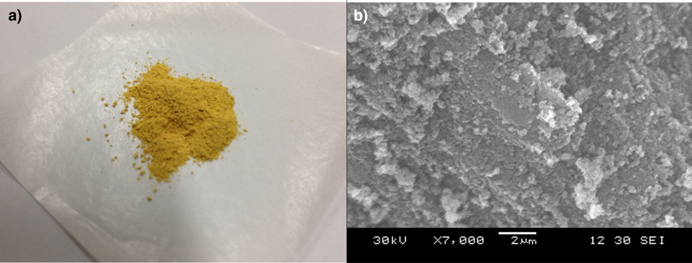
Fig. 2. The structure and morphology of HNS-IV (a) photo of submicron HNS-IV powder, and (b) SEM of HNS-IV powder.
Both single-layer Al flyer plate and three types of MFECEs were prepared via magnetron sputtering. The film was deposited on a K9 glass (Φ5 × 2 mm) by sputtering apparatus, with Ar gas flow of 1.8 × 10⁻³ m3/h and a chamber pressure of 0.4 MPa. Characterized by SEM, the surfaces of four layers are all uniform, intact and with no interstitial defects, as in Figure 3. The cross sections of four layers are layering distinctly and integrating tightly, as in Figure 4. Table 1 shows the structural parameters of the four flyer plates prepared by our laboratory and titanium/aluminum/alumina/aluminum (Ti/Al/Al2O3/Al) flyer plate by the laboratory of Bowden (Bowden Reference Bowden2015). C and Mg laser absorbed layers combined with ablation layer were selected for 0.10 with 1.00 µm and 1.00 and 0.10 µm, respectively, and had a total thickness of 6 µm approximately. The thickness of Ti/Al/Al2O3/Al flyer plate was 4.01 µm. Table 2 shows the conversion relationship between laser energy.

Fig. 3. SEM of multilayer surfaces: (a) Al; (b) Al2O3; (c) C; (d) Mg.

Fig. 4. SEM of cross section: (a) Al; (b) Al/Al2O3/Al; (c) C/Al/Al2O3/Al; (d) Mg/Al/Al2O3/Al.
Table 1. The structural parameters of the target of flyer plates

Table 2. The conversion of laser energy

Figure 5(a) shows the terminal velocity of five flyer plates driven by laser. The mazarine curve of Ti/Al/Al2O3/Al flyer plate velocity is the data of Bowden and we got the rest of the data from experiments. Terminal velocity of all four flyer plates was increased with augmenting of laser pulse energy. Under the same laser pulse energy, the MFECEs of Mg/Al/Al2O3/Al achieve the maximal terminal velocity, while the terminal velocity of other three flyer plates followed in different sequence with laser pulse energy changing. The MFECEs of Al/Al2O3/Al has the minimal terminal velocity with laser pulse energy in the range of 60.00–160.00 mJ, while the terminal velocity of C/Al/Al2O3/Al MFECEs is the lowest when laser pulse energy higher than 160.00 mJ. With laser pulse energy in the range of 60.00~160.00 mJ, the terminal velocity of single-layer Al flyer plate ranks second to Al/Al2O3/Al MFECEs. Adding absorption/ablation layer of Mg/Al to ablation structure significantly increases the terminal velocity of MFECEs. Bowden (Bowden, Reference Chen, Wu, Shen, Ye and Hu2015) added Ti/Al absorption/ablation layer in a multilayer structure to design a thinner flyer structure, the mazarine curve as shown in Figure 5(a). The Ti/Al absorption/ablation layer observably increases the coupling efficiency between laser and absorption/ablation layer. The terminal velocity of flyer plate with Ti/Al absorption/ablation layer is higher than the three types of MFECEs we prepared. It is also caused by the thinner thickness of the Ti/Al/Al2O3/Al flyer plate. Figure 5(b) shows the kinetic energies of five flyer plates driven by laser.

Fig. 5. (a) The terminal velocity of four flyer plates with different laser energy. (b) The kinetic energy of five flyer plates driven with different laser energy.
Figure 6 shows the reflectivity of the four kinds of flyer plates under the laser wavelength from 900 to 1700 nm. It is clearly seen that the addition of C/Al and Mg/Al absorption/ablation layer of nano-film materials into the MFECEs decreases the laser reflectivity of the flyer plates. That means more laser pulse energy could be used in the ablation layer of the MFECEs to generate plasma. The laser reflectivity of C/Al MFECEs was 31% lower than the single-layer Al flyer plate, but the velocity of C/Al/Al2O3/Al MFECE is not the highest. Because of the high absorptive and hardness of Mg, the absorption/ablation layer of Mg/Al can remain intact with a rather high laser pulse energy, additionally lower mass of Mg/Al, to achieve a higher velocity of flyer plate. As in Figure 7, MFECEs of Mg/Al/Al2O3/Al were sheared out of intact circular hole with different laser pulse energy, and ablation on the back of flyer plate was faint (‘back’ represents the K9 glass layer at the top in figure and ‘front’ represents the Al impact layer at the top). Meanwhile, the great thickness of Mg absorption layer also has the effect of the ablative layer to produce large amounts of plasma so that to obtain the highest velocity of flyer plate. The absorption/ablation layer of C/Al was vulnerable and fragile with laser pulse energy. As in Figure 8, flyer plates with absorption/ablation layer of C/Al was also sheared out of circular hole, but the back of C layer occur obvious disintegration, which decreases the bond between plasma to glass substrate and thermal insulation layer, causing a relatively low terminal velocity of C/Al/Al2O3/Al MFECEs with higher laser pulse energy.

Fig. 6. The reflectivity of the four kinds of flyer plates.

Fig. 7. LSCM of Mg/Al/Al2O3/Al MFECEs with different laser energy: (a) Front (36.40 mJ); (b) back (36.40 mJ); (c) front (117.80 mJ); (d) back (117.80 mJ).

Fig. 8. LSCM of C/Al/Al2O3/Al MFECEs with different laser energy: (a) Front (36.40 mJ); (b) back (36.40 mJ); (c) front (117.80 mJ); (d) back (117.80 mJ).
Figures 9(a) and 9(b) respectively show the fringe part and central part of the shear zone, which occur after Al/Al2O3/Al MFECEs ablated and launched by laser of 40.96 mJ (The laser input from the back of flyer plate). As shown in Figure 9(a), fringe part of flyer plate shear zone appear obvious melting, which caused by ablation and pull of flyer plate sheared inside the barrel, when flyer plate is driven by plasma of high pressure and temperature under high power laser. As shown in Figure 9(b), K9 glass base of film shear zone center appears crack, which caused by the shock wave when laser pulse hit flyer plate.

Fig. 9. SEM of flyer plate after shear: (a) Fringe part of the shear zone; (b) center part of the shear zone.
We analyzed the exposed K9 glass base zone by EDS, as shown in Figure 10. The element of peak not marked in the figure was the peak of gold (Au). It is a coating layer to ensure the electrical conductivity of the samples.
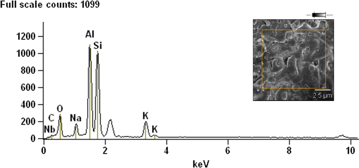
Fig. 10. EDS of shear zone center. Accelerating voltage: 20.0 Kv; magnification: 10 000.
From EDS and elements content distribution, we have found the exist of element Al in shear zone, beside elements of K9 (C, O, Na, Si, K, and Nb), which proves part of Al/Al2O3/Al MFECEs remained on K9 glass base during laser ablation.
Initiation performance for three types of MFECEs and single-layer Al flyer plate
The result of HNS-IV initiated by shocking of four flyer plates under different laser pulse energy is obtained. The flyer plate velocity is obtained by PDV system. Figure 11 shows shock initiation of HNS-IV.
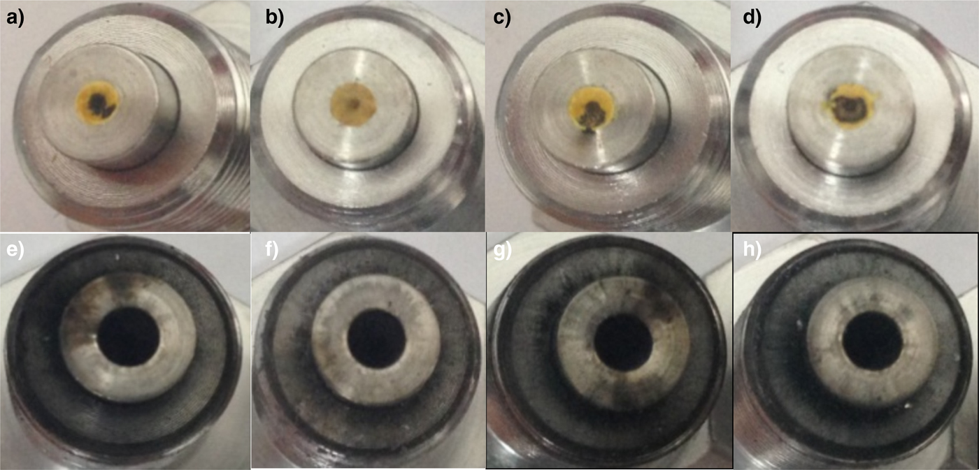
Fig. 11. Photos of HNS-IV column and cartridge after the shock initiation by flyer plate: (a) Al (78.10 mJ); (b) Al/Al2O3/Al (36.40 mJ); (c) C/Al/Al2O3/Al (36.40 mJ); (d) Mg/Al/Al2O3/Al (36.40 mJ); (e) Al (134.90 mJ); (f) Al/Al2O3/Al (53.80 mJ); (g) C/Al/Al2O3/Al (53.80 mJ); (h) Mg/Al/Al2O3/Al (53.80 mJ).
Figure 12 shows the lead plate initiated by HNS-IV pellet. The lead plate was ripped through, forming a hole with the diameter of 6.3 mm, which is far larger than the charge diameter of 2 mm, to conclude that the explosive of HNS-IV has developed a complete detonation.

Fig. 12. Lead plate ripped through by HNS-IV with the charge density of 1.6 g/cm3.
As shown in Figure 11, the surface of HNS-IV pellets was blacked without initiation, which ablated by the shock of flyer plate. Under laser pulse energy of 36.40 mJ, the shock pressure on the column increased with gradually larger of ablation spot shocked by Al/Al2O3/Al, C/Al/Al2O3/Al, and Mg/Al/Al2O3/Al MFECEs, as in the top row of Figure 11. Inner diameter of cartridge expanded significantly after initiation, as in the bottom row of Figure 11. Table 3 shows the shock initiation results by four kinds of flyer plates. From Table 3, initiation performance of MFECEs overmatched single Al flyer plate. MFECEs can successfully initiate HNS-IV when laser pulse energy is as low as 53.80 mJ, with flyer plate velocity of 2.5–2.9 km/s, while single Al flyer plate can only initiate HNS-IV when laser pulse energy is higher than 134.90 mJ, with flyer plate velocity of 4.19 km/s. Because of the limit of the laser pulse energy step length (about 8–10 mJ), all three kinds of MFECEs failed to provide initiation the HNS-IV explosive in a lower laser pulse energy at 45.20 mJ.
Table 3. The velocity and shock initiation results of the column with a charge density of 1.6 g/cm3 by Al/Al2O3/Al, C/Al/Al2O3/Al, and Mg/Al/Al2O3/Al MFECEs, and single-layer Al flyer plate

SEM of pits on the surface of HNS-IV grain shocked by Al/Al2O3/Al MFECEs under 32.24 and 40.96 mJ, are respectively shown in Figures 13 and 14.

Fig. 13. SEM of pits on surface of HNS-IV grain by Al/Al2O3/Al MFECEs under 32.24 mJ: (a) Whole morphology; (b) inner morphology of pit; (c) ablation morphology of explosive surface; (d), (e), (f), (g) inner morphology of ablated hole; (h) morphology of remained flyer plate.

Fig. 14. SEM of pits on surface of HNS-IV grain by Al/Al2O3/Al MFECEs under 40.96 mJ: (a) Whole morphology; (b) inner morphology of pit; (c), (d) ablation morphology of explosive surface; (e) morphology of remained flyer plate; (f), (g), (h) inner morphology of ablated hole.
As shown in Figures 13 and 14, obvious pits appear on HNS-IV grain by the shock of Al/Al2O3/Al MFECEs. Figure 13(a) shows the pit became clearer with higher laser pulse energy, due to the shock of flyer plate forming a crack at the bottom of pit deep inside the grain. As shown in Figures 13(a) and 14(a), the pits on the explosive were deeper and more irregular under higher laser pulse energy, to obtain the poor integrity of flyer plate under 40.96 mJ. On the surface of the pit, we found flyer plate has ablated holes, with different size and shape, and deep inside the grain. The result shows a partially molten flyer plate and burst on the surface of grain to form holes in the flyer plate with high temperature and pressure. Meanwhile, we found part of flyer plate remained on the surface of the pit, and we analyze the remained flyer plate on the surface of the pit and inside hole by EDS. We found element Al and Si, in addition to elements of HNS-IV(C, N, and O), but only element C, O, and Al on remained flyer plate. On the surface of the pit and inside the ablated hole, element Al remained on the explosive surface by ablating and melting of flyer plate shocking. Element Si remained on grain surface by the shock of partial glass, when flyer plate driven by laser and K9 glass base ablated by plasma of high temperature and pressure. EDS of remained flyer plate on the surface of HNS-IV grain by Al/Al2O3/Al MFECEs under 32.24 and 40.96 mJ, are respectively shown in Figures 15 and 16. From EDS and elements content distribution, the content of element Al reduces with higher laser pulse energy, due to ablating and melting appearance of flyer plate become clearer by higher energetic plasma.

Fig. 15. EDS of remained flyer plate with laser energy of 32.24 mJ. Accelerating Voltage: 20.0 kV; Magnification: 1000.
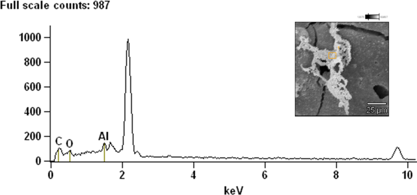
Fig. 16. EDS of remained flyer plate with laser energy of 40.96 mJ. Accelerating Voltage: 20.0 kV; Magnification: 1000.
Initiation results analysis
An initiation criterion of an explosive could only occur when the energy fluence imparted to the explosive exceeded a certain critical value (Walker et al., Reference Walker, Wasley, Green and Nidick1973; Dobratz and Crawford, Reference Dobratz and Crawford1985) given by
where P is the shock pressure on the surface of explosive by flyer plate, U is the particle velocity and τ the pulse duration of shock pressure.
Table 4 shows the shock initiation parameters of HNS-IV. The shock duration for initiation HNS-IV explosive at these high pressures is 1.8–2.2 ns. As shown in Figure 17, Bowden's data (Bowden et al., Reference Bowden, Maisey and Knowles2012) provide a higher energy fluence than MFECEs and lower energy fluence than single-layer Al flyer plate. The energy fluence of MFECEs and Bowden's results approach a constant value (approximately 0.06 and 0.09 MJ/m2, respectively) as the pressure changes. The MFECEs of Al/Al2O3/Al has the minimum energy fluence and shock initiation pressure in the same laser pulse energy. Under the same laser pulse energy, the flyer mass of the C/Al MFECEs is higher than Al/Al2O3/Al, and the flyer mass of Mg/Al MFECEs is lower than Al/Al2O3/Al, as shown in Figure 5(b); but the velocity of C/Al and Mg/Al MFECEs are much higher than Al/Al2O3/Al flyer plate, therefore, the energy fluence of Al/Al2O3/Al flyer plate is the lowest, as shown in Table 4. It shows that the MFECEs can initiate HNS-IV explosive under the lower laser pulse energy. And the P–τ values of shock initiation HNS-IV are clear trends in Figure 18. It shows that the single-layer Al flyer plate has comparatively higher initiation pressure and the shock initiation pressure of MFECEs is relatively low compared with the experimental results of Bowden. That's because the laser pulse energy and velocity of single-layer Al flyer plate are 47.74 J/cm2 and 4190 m/s, respectively, which are greater than the initiation energy used by MFECEs and Bowden.
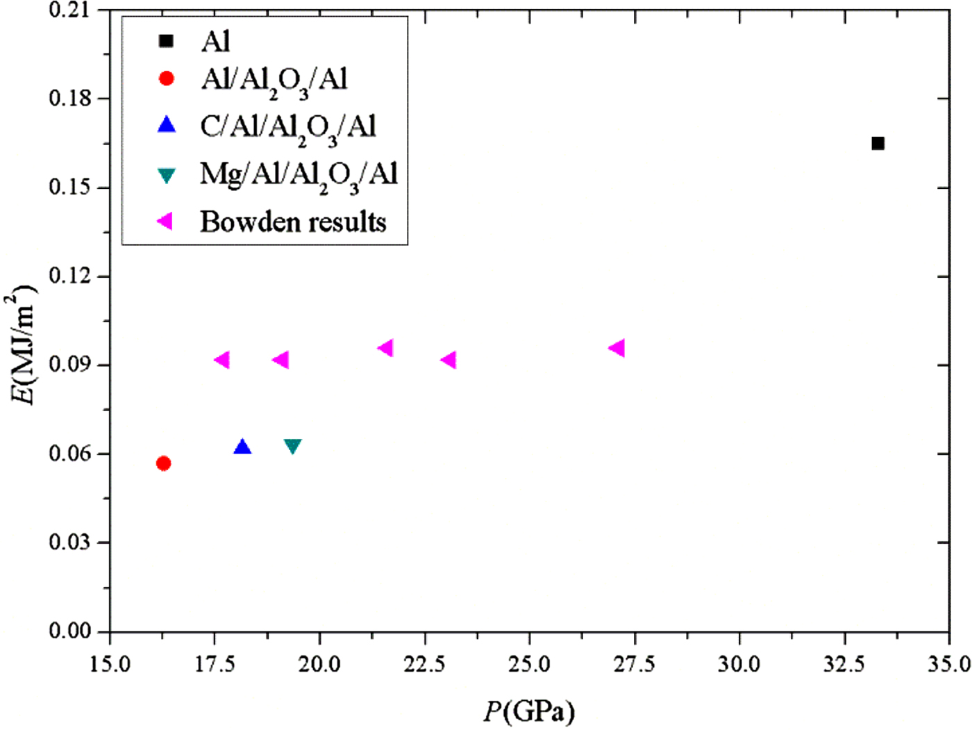
Fig. 17. Energy fluence versus imparted shock pressure.

Fig. 18. P–τ values of shock initiation on HNS-IV.
Table 4. The shock initiation parameters of experimental results

According to the James criterion about critical shock initiation energy of heterogeneous explosive (James, Reference James1996):
where ![]() ${\rm \sum} $ is the specific kinetic energy, E is the energy fluence,
${\rm \sum} $ is the specific kinetic energy, E is the energy fluence, ![]() ${\rm \sum} _{\rm c} $ and E c are constant parameters by the characteristics of HNS-IV. P is the shock pressure on the surface of explosive by flyer plate, τ is the duration of shock pressure, u is the particle velocity.
${\rm \sum} _{\rm c} $ and E c are constant parameters by the characteristics of HNS-IV. P is the shock pressure on the surface of explosive by flyer plate, τ is the duration of shock pressure, u is the particle velocity.
The James criterion of the HNS-IV explosive can be expressed as follows given by Bowden et al. (Reference Bowden, Maisey and Knowles2012) (![]() ${\rm \sum} _{\rm c} {\rm = 0}{\rm. 2042}$, E c = 0.0879)
${\rm \sum} _{\rm c} {\rm = 0}{\rm. 2042}$, E c = 0.0879)
Figure 19 presents The E–Σ values of experimental results and Bowden's date (Bowden et al., Reference Bowden, Maisey and Knowles2012). The James criterion displays a great sensitivity to the layer structure of laser-driven flyer plate, with the MFECEs having a lower E c and a higher ![]() ${\rm \sum} _{\rm c} $ than the results of Bowden. Comparing with both the date of MFECEs and Bowden, the single-layer Al flyer plate has a higher E c and a lower
${\rm \sum} _{\rm c} $ than the results of Bowden. Comparing with both the date of MFECEs and Bowden, the single-layer Al flyer plate has a higher E c and a lower ![]() ${\rm \sum} _{\rm c} $.
${\rm \sum} _{\rm c} $.

Fig. 19. The specific kinetic (Σ) versus energy fluence (E).
Adding a thermal insulating layer of Al2O3 (3.97 g/cm3, Mons’ hardness scale 8.8) and laser absorption/ablation layer of Mg/Al and C/Al, thermal stability, and laser availability of flyer plate are improved, respectively. High hardness material of thermal insulation protects flyer plate in plasma ablation of high temperature and pressure, to ensure the integrity and increases the hardness of the Al (2.7 g/cm3, Mons’ hardness scale 2.75) flyer plates. Under the same laser pulse energy, the final velocity of C/Al and Mg/Al MFECEs increase to 4577.4 m/s and 5061 m/s, respectively. Meantime the velocity of Al/Al2O3/Al MFECEs (up to 4504.6 m/s) is 1.07% lower than the single-layer Al flyer plate (up to 4553.2 m/s). The mass of three types MFECEs are 11.2% greater than that of the single-layer Al flyer plate (Chen et al., Reference Chen, Wu, Shen, Ye and Hua2013b). The kinetic energy of the MFECEs is greater than that of the single-layer Al flyer plate. And the elastic modulus of Al2O3 (300 GPa) is larger than Al elastic modulus (72 GPa), so the addition of Al2O3 insulating layer makes the increase of MFECEs elastic modulus. The elastic deformation capacity weakens while the shock of MFECEs and reduced the shock duration time. According to the theorem of momentum (Ft = mv), the shock pressure of the MFECEs significantly higher than the single-layer Al flyer plate, which greatly improves the initiation capacity of laser-driven flyer plate shock on HNS-IV.
We analyze shear morphology and initiation result of flyer plate, and found shock initiation performance of HNS-IV significantly reduce with the structure of MFECEs. The integrity of flyer plate deteriorate with higher laser pulse energy, but initiating ability of MFECEs significantly improve, due to laser utilization of flyer plate improves with the addition of C/Al and Mg/Al laser absorption/ablation layer, and adding Al2O3 thermal insulation layer to protect flyer impact layer. Shock initiation performance of three MFECEs is better than single-layer Al flyer plate. These results support a better design of flyer structure for superior performance. Based on these conclusions, we will continue research, combining with laser ablation theory, to design more reasonable multilayer structure for MFECEs and best thickness for each layer. By increasing shock pressure of flyer plate, HNS-IV can successfully initiate under much lower laser pulse energy. These results have guiding significance on laser driving multilayer flyer shock initiation.
Conclusion
In this study, both single-layer Al flyer plate and three types of MFECEs (Al/Al2O3/Al, C/Al/Al2O3/Al, and Mg/Al/Al2O3/Al) were prepared by magnetron sputtering. Characterized by SEM, surface morphology, and cross-section show the structure of each thin film is clear, and layers combined tightly. Using PDV system to the measurement, the velocity of four flyer plates shows, the MFECEs with absorption/ablation layer of Mg/Al and the thermal insulation layer of Al2O3 have the maximum terminal velocity under the same laser pulse energy. Due to the multilayer structure of flyer plate, the initiation energy of sub-micron HNS-IV by MFECEs is effectively reduced to 53.80 mJ. MFECEs achieve higher kinetic energy at lower laser pulse energy. These results have guiding significance to reduce initiation threshold of laser-driven flyer plate in development of laser flyer initiation technology.
Acknowledgments
This work was supported by the Natural Science Foundation of China (grant no. 11202105 and 11672137).


