I. INTRODUCTION
NOWADAYS there is a growing interest in devices for implantable biotelemetry applications in the Medical Device Radio communications Service [Reference Ashok Kumar and Shanmuganantham1]. In order to improve the quality of the patient life, the whole system, including the antenna, must be as small as possible. This, along with the choice of the Medical Implantable Communication Services band implies the use of an electrically small antenna [Reference Scarpello2–Reference Chien5]. Such antennas are very sensitive to their surrounding environment. The properties of implanted antennas are indeed strongly affected by the presence of the human body. So as to predict these modifications, many “body phantoms” have been developed and are available in [Reference Liu, Yeh and Ghavami6, Reference Liu, Chen and Wu7]. These models describe the human body with different accuracy. Particular attention is paid to the fact that the human body is constituted of highly lossy materials for radio frequency (RF) propagation, for instance at 403.5 MHz for muscle tissue [8]. Communication between the implanted antenna and the external base station is significantly affected.
For instance, the biocompatible insulation is necessary to prevent metallic oxidation and to avoid any short-circuit effect due to the high conductivity of some human body tissues [Reference Sánchez-Fernández, Quevedo-Teruel, Requena-Carrión, Inclán-Sánchez and Rajo-Iglesias9]. In particular, the biocompatible insulation affects the electromagnetic radiation in different physical ways, it smooth's the transition of the radiating wave between the source and the body model; it also reduces the coupling of the high near-field terms of the electromagnetic radiation in the surrounding living tissue [Reference Karacolak, Hood and Topsakal10]. The latter plays a principal role in the radiation efficiency of the implanted antenna. As clearly pointed out in these works, varying the insulation properties strongly modifies the radiation characteristics and hence the input impedances, matching and efficiencies. Radiation efficiencies at different resonant frequencies and/or matching levels are compared in [Reference Rahmat-Samii and Kim11–Reference Lee, Yo, Huand and Luo13]. In this paper, an implanted antenna for the human body medical device, their characteristics, and human body as a medium for RF propagation at 2.45 GHz are designed.
Some patients find difficulty in checking up their health condition daily at the hospital. This proposed system may be better replacement for this issue. In such a case, an implantable antenna can be placed in the patient's body. This antenna can communicates patient condition regularly to the concern person at the hospital as shown in Fig. 1 [Reference Lee, Yo and Luo14]. In this case, patient save the transport charges and time, at the same time doctor serves several patients at a time.

Fig. 1. Hospital applications of proposed antenna.
The organization of this paper is summarized as follows. In Section II, the geometrical details of the proposed antenna are discussed. This follows Section III, which details the operating principle of the implantable coplanar waveguide (CPW)-fed antenna. This section also provides the proof that the proposed antenna is much suitable for industrial, scientific, and medical (ISM) band medical applications with its simulation and measured results. This is followed by the conclusion remark in Section IV.
II. GEOMETRY OF THE PROPOSED ANTENNA
A) Antenna design
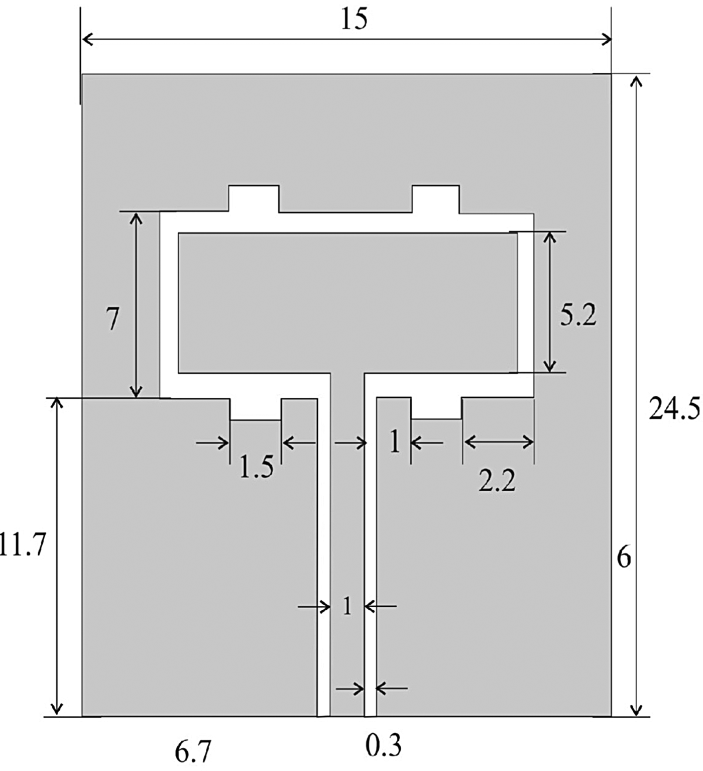
Figure 2 shows the geometry of implantable CPW-fed rectangular patch antenna for 2.45 GHz ISM band biomedical applications. The antenna is printed on a 15 mm × 24.5 mm FR4 substrate with thickness of 1.6 mm and relative permittivity of 4.4. A 50-Ω CPW transmission line of a signal strip width of 1 mm, with a gap distance of 0.5 mm between the strip and the coplanar ground plane is used for feeding the antenna. L-shaped monopoles with slots are designed for ISM band biomedical operations.
Fig. 2. Proposed antenna structure (all dimensions are in mm).
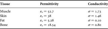
The feeding structure of the rectangular patch antenna consists of a CPW with matching the mode impedance of 50 Ω is obtained by tuning the distance between the tracks and as well as the width of the tracks as shown in Fig. 2. The proposed antenna design model setup is shown in Fig. 3. The values for each couple of dielectric values reported in Table 1 [Reference Sánchez-Fernández, Quevedo-Teruel, Requena-Carrión, Inclán-Sánchez and Rajo-Iglesias9] valid at the specified frequency.
Fig. 3. Antenna design setup model.
Table 1. Dielectric properties of human tissues.
B) Electrical properties of pork tissue
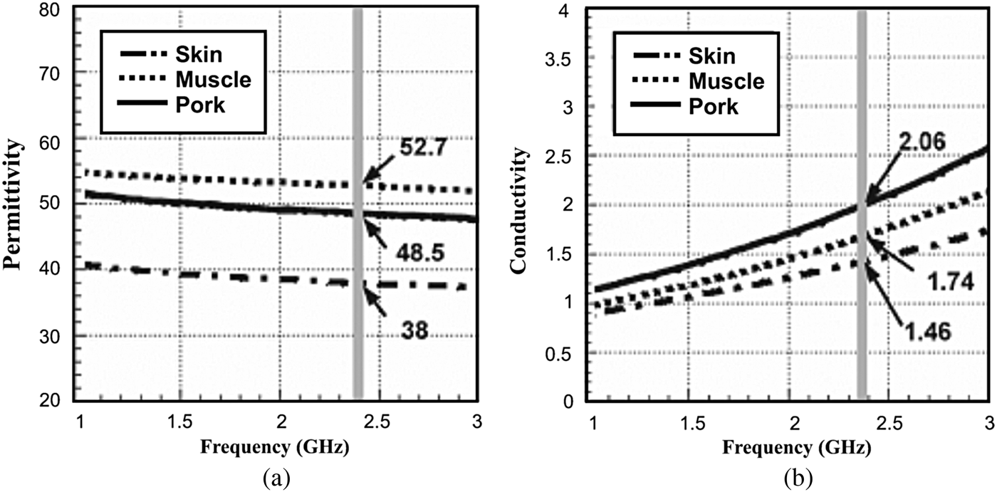
In present studies, simulated human skin fluids were developed by varying the concentrations of alcohol and salt [Reference Lee, Yo and Luo14]. Here minced pork was adopted to offer an easy approach to mimicking the environment of ISM band applications and to verify the characteristics of the proposed antenna. In this case, the experimental test tissue was a front leg tissue of pork. Agilent's dielectric probe kit and network analyzer were used to make the dielectric measurements and the measurements were taken of the test tissue between 300 and 3000 MHz as shown in Fig. 4. The dimensions of the test tissue were 250 mm × 250 mm × 80 mm. Figure 5 compares the permittivity and conductivity of the test tissue (pork) with that of reference skin and muscle [Reference Soontornpipit15]. Therefore, it is suitable for verifying the ISM band implantable CPW-fed antenna design.
Fig. 4. Dielectric measurement (pork tissue).
Fig. 5. Electrical properties of pork tissue at 2.45 GHz: (a) permittivity, (b) conductivity.
III. RESULTS AND DISCUSSION
Experimental investigations are necessary in order to validity the numerical simulations for implantable CPW-fed antennas. Since it is not possible to carry out measurements inside the human body, investigations are performed by measuring laboratory-fabricated prototypes (Fig. 6) inside tissue-equivalent media (phantoms).
Fig. 6. Fabricated proposed antenna.
A) Fabrication
Prototype fabrication of implantable antennas meets all classical difficulties of miniature antennas. The coplanar waveguide feed used to connect the antenna with the network analyzer may give rise to radiating currents on the outer part of the cable, which, in turn, deteriorate measurements (Fig. 7). The effects of different feeding techniques for implantable patch antennas were analyzed in [Reference Wong16]. Rectangular patch antenna prototypes immersed inside phantoms, with the ground plane being in direct contact with the tissue-emulating material, were found to be insignificantly influenced by the coaxial cable. Based on the above, the numerical antenna model must be slightly adjusted in order to take prototype fabrication considerations into account. Example fabricated prototypes of implantable antenna is shown in Fig. 6.
Fig. 7. (a) Experimental return loss measurement. (b) Photograph for experimental setup.
B) Inside phantoms
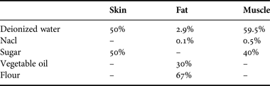
Measuring inside phantoms are relatively easy and practical to implement. The fabricated prototype is immersed inside a human body phantom liquid and measured. Any shaped phantoms have so far been used for testing implantable antennas. In this case, the main challenge lies in the formulation and characterization of tissue emulating materials. Example phantoms and tissue recipes reported in the literature are given in Table 2 [Reference Karacolak, Hood and Topsakal10, Reference Rahmat-Samii and Kim11, 12, Reference Wong16].
Table 2. Phantoms used for testing of implantable antennas.
Testing inside animal tissue can be performed by implanting antenna inside tissue samples from donor animals, or by surgically implanting the antenna inside live model animals. In the first case, electrical properties of the test tissue can be measured using a dielectric probe kit and a network analyzer. The use of animal tissue samples provides an easy approach to mimic the frequency dependency characteristics of the electrical properties of tissues. This can prove highly advantageous when carrying out measurements for multi-band implantable antennas. In the literature, an implantable patch antenna with dual resonances at 380 and 440 MHz was tested inside test tissue obtained by grinding the front leg of a pig. The electrical properties of the adapted pork were found to be between those of human skin and muscle in the ISM band (Fig. 5).
Recipes proposed mainly included ultra-pure water, sugar, and salt contents. An increase in sugar content concentration has been found to drastically decrease ε r, while slightly increasing σ. An increase in salt content concentration decreases ε r and significantly increases σ tabulated in Table 3 [Reference Karacolak, Cooper and Topsakal17]. Adding an agarose to solidify the liquids and form multilayer gel phantoms was also examined.
Table 3. Preparation of human body phantom liquids.
C) Antenna characteristics
The experimental measurements must be carried out with the exact same antenna structure in order to be able to validate the design and return loss characteristics of pork tissue, human phantom liquid, and simulated results are plotted in Fig. 8. It can be found to correspond to those of human skin and muscle between 300 MHz and 3 GHz. Typical current distribution of proposed antenna shows maximum current in edges as shown in Fig. 9. Finally, an implantable antenna was tested inside a minced leg of a pig. In-vivo investigations are also vital in order to investigate the effects of live tissue on the performance of implantable patch antennas, while providing valuable feedback for antenna design and analysis.
Fig. 8. Comparison of return loss versus frequency.
Fig. 9. Current distribution at 2.45 GHz.
The radiation characteristics of the antenna inside the liquid-simulating muscle, fat, and skin tissue are determined in terms of radiation patterns and gain. To simulate, the antenna is directed toward the surface of the gel (muscle, fat, and skin) and along the z-direction the distance to the surface of the gel is set to 15 mm in the xy-plane, the antenna is placed in the center of the surface of the human model phantom. The computed radiation patterns in the E-plane and H-plane are shown in Figs 10 and 11, respectively. The patterns are computed at 2.45 GHz, at a reference distance of 1 m and using an input power of 1 W.
Fig. 10. Radiation pattern for H-field: (a) co-polarization, (b) cross-polarization.
Fig. 11. Radiation pattern for H-field: (a) co-polarization, (b) cross-polarization.
The maximum gain is equal to −6 dBi for θ = 0 and φ = 0 and the radiation efficiency is 0.34%. These values are comparable to other results in literature [Reference Karacolak, Hood and Topsakal10]. The radiation efficiency is very low because the antenna is not in free space, but embedded into human tissue, simulated as a very lossy tissue medium.
IV. CONCLUSION
In this paper, a novel implantable CPW-fed rectangular patch antenna for biomedical applications is presented with a compact size of (15 mm × 24.5 mm × 1.6 mm) and solutions suggested regarding the design, simulations, and experimental investigations of implantable CPW-fed patch antenna for biomedical telemetry. The design of implantable antennas mainly emphasizes miniaturization and biocompatibility. Conserving energy to extend the life span of the implantable medical device is also significant. ISM band antennas are being designed for these purposes that “wake up” the implantable medical device only when there is a need for information exchange.
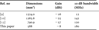
A homogenous model is plenty for antenna design, a more sensible model is needed to refine the antenna design and provide perfect results. Owing to better dielectric constant of the substrates, implantable antenna exhibit miniaturization, lower return loss, good voltage standing wave ratio (VSWR), better impedance matching, and high gain compared to over the other implanted antennas (Table 4). Therefore, the proposed antenna is the suitable candidate for ISM band frequency of 2.45 GHz in the field of Biomedical Engineering.
Table 4. Comparison results of other implanted antennas.
 Srinivasan Ashok Kumar received the B.E. degree in Electronics and Communication Engineering from Anna University, Chennai, India, in 2006 and M.E. degree in Applied Electronics from Thanthai Periyar Government Institute of Technology, Anna University, Chennai, India, in 2009. He has 2 years of teaching experience in Adhiparasakthi Engineering College, Melmaruvathur. He is currently working toward the Ph.D. at Department of Electronics Engineering, School of Engineering and Technology, Pondicherry University (Central University), Pondicherry, India. He has authored for one book chapter and 16 journal and conference papers. His current research interest includes antenna theory, biomedical telemetry, and implantable antennas.
 Thangavelu Shanmuganantham received the B.E. degree in Electronics and Communication Engineering from University of Madras in the year 1996, M.E. degree in Communication Systems from Madurai Kamaraj University in the year 2000 and Ph.D. (Gold Medal) in the area of Antennas from National Institute of Technology, Tiruchirappalli, Meta- India in the year 2010 under the guidance of Dr. S. Raghavan. He has 15 years of teaching experience in various reputed Engineering colleges such as SSN College of Engineering, National Institute of Technology and Science. Presently he is working as an Assistant Professor in Department of Electronics Engineering, School of Engineering & Technology, Pondicherry University, Pondicherry. His research interest includes Antennas, Microwave/Millimeter-Wave Circuits and Devices, Microwave Integrated Circuits, EMI/EMC, Computational Electromagnetics, MEMS/NEMS, materials. He has published 75 research papers in various national and International level Journals and Conferences. He has completed one sponsored project and two projects are in the pipeline. He is a coordinator for MEMS Design Center, NPMASS. His biography was included in Marquis Who is Who in the World, USA in the year 2010. He is a member in IEEE, Life Member in IETE, Institution of Engineers, CSI, Society of EMC, ISSS, OSI, ISI, ILA, and ISTE.