


1 Introduction
A detonation in a condensed-phase explosive consists of a shock sustained by the hydrodynamic flow induced by spatially distributed chemical reaction in the explosive. In typical multi-dimensional flow configurations, lateral motion of the detonating explosive induces streamline divergence which causes the shock to become divergently curved and the flow sonic locus (in the frame of the propagating detonation) to move into regions of incomplete reaction (Bdzil Reference Bdzil1981; Short & Quirk Reference Short and Quirk2018b ). In steady flow, an important structure arises known as the detonation driving zone (DDZ). This comprises the subsonic elliptic flow region spatially bounded by the detonation shock and the sonic flow locus. Only the chemical energy release in the subsonic DDZ flow region influences the detonation motion (Bdzil Reference Bdzil1981; Short & Quirk Reference Short and Quirk2018b ). A major goal of condensed-phase detonation research is to determine the influence that material properties of the explosive confinement have on the structure of the DDZ.
The principal effect of confinement on the DDZ structure can be understood through two-dimensional (2D) hydrodynamic flow analysis. Broadly, we can divide the influence of the confinement into two classes, corresponding to either strong (confined) or weak (unconfined) configurations (Bdzil & Stewart Reference Bdzil and Stewart2007). The basic flow structure for strong confinement is shown in figure 1(a), and typically occurs for high-density and moderate-sound-speed confiner materials such as metals. It is characterized by a flow structure in which the sonic locus intersects the deflected material interface downstream of where the detonation shock intersects the material interface. The flow along the material interface in the high explosive (HE) is subsonic ahead of the sonic locus, while that on the confiner side can be subsonic or supersonic. Behind the sonic locus, the flow in the HE is supersonic, and thus can be analysed by characteristic methods for a non-isentropic flow. Information about the confiner properties enter the supersonic HE region propagated along
 $C^{+}$
characteristics from the confiner material interface. These characteristics are generally assumed to carry information downstream of the sonic locus. A bounding characteristic defines the extent of penetration of the confinement boundary influence in the supersonic HE flow region, as shown schematically in figure 1(a). With the bounding
$C^{+}$
characteristics from the confiner material interface. These characteristics are generally assumed to carry information downstream of the sonic locus. A bounding characteristic defines the extent of penetration of the confinement boundary influence in the supersonic HE flow region, as shown schematically in figure 1(a). With the bounding
 $C^{+}$
characteristic not intersecting the sonic flow locus, the material properties of the confiner influence the DDZ structure only through the material interface region ahead of the sonic locus. The DDZ structure is determined by the subsonic elliptic flow problem bounded by the detonation shock, sonic locus and material interface region ahead of the sonic flow locus. As a result, the detonation phase speed varies with the material properties of the confiner material, as recently reviewed by Short & Quirk (Reference Short and Quirk2018b
).
$C^{+}$
characteristic not intersecting the sonic flow locus, the material properties of the confiner influence the DDZ structure only through the material interface region ahead of the sonic locus. The DDZ structure is determined by the subsonic elliptic flow problem bounded by the detonation shock, sonic locus and material interface region ahead of the sonic flow locus. As a result, the detonation phase speed varies with the material properties of the confiner material, as recently reviewed by Short & Quirk (Reference Short and Quirk2018b
).

Figure 1. Schematic of (a) strong and (b) weak confinement flow structures.
The basic flow structure for weak confinement is shown in figure 1(b). Weak confinement typically occurs for low-density, low-sound-speed materials such as plastics, and include cases of no confinement (air/vacuum). Weak confinement is characterized by a flow structure in which the sonic locus intersects the detonation shock at the material interface (figure 1
b). The flow at the material interface behind the detonation shock is then sonic, while the flow along the material interface in the HE behind the sonic locus is supersonic. At the explosive edge, an expansion fan forms in the supersonic flow region downstream of the sonic locus, centred on the detonation shock, sonic locus and material interface intersection point. Its role is to reduce the pressure in the HE behind the detonation shock near the explosive edge to that in the confiner. As above, the influence of the confiner material properties in the supersonic HE region is defined by the
 $C^{+}$
characteristics originating on the material interface downstream of the sonic point. A bounding characteristic again defines the extent of penetration of the confinement influence in the supersonic HE region. For sufficiently weak confinement, this bounding characteristic lies to the right of the sonic locus (bounding characteristic 1 in figure 1
b), and thus the confinement properties do not influence the DDZ structure (Stewart & Bdzil Reference Stewart and Bdzil1989). Consequently, the DDZ structure is determined by the elliptic flow region bounded by the detonation shock and sonic locus. Flow characteristics in the supersonic HE flow regime have been calculated by Gamezo & Oran (Reference Gamezo and Oran1997) for two unconfined explosives of different thicknesses and appear to show they do not influence the DDZ structure. With strengthening of the confinement, the bounding characteristic moves towards the sonic locus of the DDZ, but provided the bounding characteristic does not intersect the sonic locus, the DDZ structure, and thus the phase speed of the detonation, will be unaffected by the changes in the confinement properties. As the confinement is further strengthened, a point on the bounding characteristic will first become tangent to the sonic surface, as shown in figure 1(b) (bounding characteristic 2). At this point, the DDZ structure remains unaffected by the confinement material properties. However, for any additional increase in the confinement strength, the DDZ structure is now influenced by confinement boundary information propagating along the
$C^{+}$
characteristics originating on the material interface downstream of the sonic point. A bounding characteristic again defines the extent of penetration of the confinement influence in the supersonic HE region. For sufficiently weak confinement, this bounding characteristic lies to the right of the sonic locus (bounding characteristic 1 in figure 1
b), and thus the confinement properties do not influence the DDZ structure (Stewart & Bdzil Reference Stewart and Bdzil1989). Consequently, the DDZ structure is determined by the elliptic flow region bounded by the detonation shock and sonic locus. Flow characteristics in the supersonic HE flow regime have been calculated by Gamezo & Oran (Reference Gamezo and Oran1997) for two unconfined explosives of different thicknesses and appear to show they do not influence the DDZ structure. With strengthening of the confinement, the bounding characteristic moves towards the sonic locus of the DDZ, but provided the bounding characteristic does not intersect the sonic locus, the DDZ structure, and thus the phase speed of the detonation, will be unaffected by the changes in the confinement properties. As the confinement is further strengthened, a point on the bounding characteristic will first become tangent to the sonic surface, as shown in figure 1(b) (bounding characteristic 2). At this point, the DDZ structure remains unaffected by the confinement material properties. However, for any additional increase in the confinement strength, the DDZ structure is now influenced by confinement boundary information propagating along the
 $C^{+}$
characteristics, and a transition to the strong confinement case discussed above will ensue (Stewart & Bdzil Reference Stewart and Bdzil1989).
$C^{+}$
characteristics, and a transition to the strong confinement case discussed above will ensue (Stewart & Bdzil Reference Stewart and Bdzil1989).

Figure 2. Schematic of
 $C^{+}$
characteristics for weak confinement originating from the expansion fan centred at the intersection of the detonation shock and sonic locus and impinging on the sonic locus. Based on a schematic shown in Bdzil (Reference Bdzil1981).
$C^{+}$
characteristics for weak confinement originating from the expansion fan centred at the intersection of the detonation shock and sonic locus and impinging on the sonic locus. Based on a schematic shown in Bdzil (Reference Bdzil1981).
Asymptotic studies by Bdzil (Reference Bdzil1976, Reference Bdzil1981) and Bdzil, Short & Chiquete (Reference Bdzil, Short and Chiquete2018) raised the possibility that, for weak confinement,
 $C^{+}$
characteristics emerging from the expansion fan singularity at the intersection of the detonation shock and sonic locus and travelling through the supersonic flow region can impinge on the sonic locus and deposit information about the fan solution on the sonic locus of the DDZ (figure 2). The studies of Bdzil (Reference Bdzil1976) and Bdzil et al. (Reference Bdzil, Short and Chiquete2018) were based on a simplified small resolved heat release model in which most of the reaction occurs instantaneously at the detonation shock, while that of Bdzil (Reference Bdzil1981) involved a local analysis of the Prandtl–Meyer (PM) fan in the region of the intersection of the detonation shock and material interface. The implications are that the sonic locus and subsonic elliptic flow region defining the DDZ structure could depend on information carried by the fan characteristics and propagated through the supersonic region behind the sonic locus. A limiting characteristic (figure 2) defines the boundary between
$C^{+}$
characteristics emerging from the expansion fan singularity at the intersection of the detonation shock and sonic locus and travelling through the supersonic flow region can impinge on the sonic locus and deposit information about the fan solution on the sonic locus of the DDZ (figure 2). The studies of Bdzil (Reference Bdzil1976) and Bdzil et al. (Reference Bdzil, Short and Chiquete2018) were based on a simplified small resolved heat release model in which most of the reaction occurs instantaneously at the detonation shock, while that of Bdzil (Reference Bdzil1981) involved a local analysis of the Prandtl–Meyer (PM) fan in the region of the intersection of the detonation shock and material interface. The implications are that the sonic locus and subsonic elliptic flow region defining the DDZ structure could depend on information carried by the fan characteristics and propagated through the supersonic region behind the sonic locus. A limiting characteristic (figure 2) defines the boundary between
 $C^{+}$
characteristics that impinge on the sonic surface and those that propagate information downstream of the sonic surface. A similar situation arises for supersonic and hypersonic flow over a blunt body, as described by Hayes & Probstein (Reference Hayes and Probstein1966), where the sonic surface connecting the bow shock to the body are influenced by the impingement of supersonic flow characteristics from behind the sonic surface. The enclosed subsonic elliptical flow region around the axis for blunt-body flows is thus affected by supersonic flow regions beyond the sonic surface. A limiting characteristic is also similarly defined for blunt-body flows.
$C^{+}$
characteristics that impinge on the sonic surface and those that propagate information downstream of the sonic surface. A similar situation arises for supersonic and hypersonic flow over a blunt body, as described by Hayes & Probstein (Reference Hayes and Probstein1966), where the sonic surface connecting the bow shock to the body are influenced by the impingement of supersonic flow characteristics from behind the sonic surface. The enclosed subsonic elliptical flow region around the axis for blunt-body flows is thus affected by supersonic flow regions beyond the sonic surface. A limiting characteristic is also similarly defined for blunt-body flows.
To date, for detonation flows, we have an incomplete understanding of the nature of the characteristic paths in the HE supersonic flow region behind the sonic locus of the DDZ structure. This includes how they could carry information about the confinement properties through the supersonic flow region and ultimately impinge on the DDZ and affect its shape, the behaviour of the characteristics during the transition from weak to strong confinement, and also the relationship between the limiting and bounding characteristics during the transition. The purpose of this article is twofold. First, we analyse the characteristic paths defining the influence of the confinement boundary in the supersonic HE flow regime beyond the sonic locus of the DDZ for a variety of confinement conditions in order to establish whether information about the confinement is able to reach the sonic locus through the HE supersonic flow regions. Thin and thick 2D planar geometries are explored, as well as cylindrical geometries. We generally find that the picture of the flow of information in the supersonic region described in figures 1 and 2 is significantly more complicated for both weakly and strongly confined detonations. Secondly, we study the ability of oblique-shock polar analysis to capture the corresponding state of the flow at the explosive edge. Oblique-shock polar analyses have proven useful in the understanding of the basic flow structures of strongly and weakly confined detonation propagation, focusing on the region where the detonation shock intersects the material interface. A review of the application of shock polar analysis to the understanding of the DDZ structure has recently been given by Short & Quirk (Reference Short and Quirk2018b ). We find here that, while a shock polar analysis can adequately describe the local flow structure near the edge of the explosive for a specified detonation phase speed, it provides limited information on the non-local, global steady DDZ detonation structure that arises due to influence of characteristics impinging on the sonic surface.
One computational strategy to explore these issues is via multi-material numerical calculations (Short & Quirk Reference Short and Quirk2018b ). However, it is difficult to systematically control the interface deflection angles at the detonation shock using disparate material confiners. Also, the streamline deflection angle at the explosive edge is difficult to calculate accurately due to numerical issues with multi-material interface capturing methods (Short & Quirk Reference Short and Quirk2018b ). Instead, we use a simplified strategy recently used by Chiquete et al. (Reference Chiquete, Short, Meyer and Quirk2018a ) and Chiquete, Short & Quirk (Reference Chiquete, Short and Quirk2018b ) to study confined and unconfined detonation propagation. In these shock and wall-boundary-fitted calculations, a solid wall boundary is deflected through a specified angle on detonation shock arrival. The streamline turning angle of the wall at the edge of the explosive is then unambiguously defined. By varying the wall turning angle from small through large values, we can systematically capture the evolution of the DDZ structure and the flow regions that influence its structure for strongly confined to weakly confined detonations.

Figure 3. (a) Schematic of axial detonation propagation in either a 2D planar geometry (
 $\unicode[STIX]{x1D6FD}=T/2$
) or axisymmetric 2D cylindrical geometry (
$\unicode[STIX]{x1D6FD}=T/2$
) or axisymmetric 2D cylindrical geometry (
 $\unicode[STIX]{x1D6FD}=R$
), in which a solid wall HE boundary is deflected through an angle
$\unicode[STIX]{x1D6FD}=R$
), in which a solid wall HE boundary is deflected through an angle
 $\unicode[STIX]{x1D703}$
upon detonation arrival. For computational purposes, the laboratory-frame
$\unicode[STIX]{x1D703}$
upon detonation arrival. For computational purposes, the laboratory-frame
 $(r,z)$
geometry in (a) is mapped to the shock- and deflected wall-boundary-fitted frame
$(r,z)$
geometry in (a) is mapped to the shock- and deflected wall-boundary-fitted frame
 $(\unicode[STIX]{x1D709},\unicode[STIX]{x1D702})$
shown in (b).
$(\unicode[STIX]{x1D709},\unicode[STIX]{x1D702})$
shown in (b).
In practice, there will be some curvature of the material interface as a result of the pressure distribution on the interface. However, both theoretical (Bdzil Reference Bdzil1981; Vidal et al. Reference Vidal, Cowperthwaite, Presles and Bouton1994) and numerical (Sharpe & Braithwaite Reference Sharpe and Braithwaite2005; Watt et al. Reference Watt, Sharpe, Falle and Braithwaite2012; Short & Quirk Reference Short and Quirk2018b ) studies of the 2D steady-state DDZ structure for multi-material flows have shown that, at least in the vicinity of the DDZ, the magnitude of the interface curvature can be small and that, for a number of confinement scenarios, the interface is approximately straight relative to its deflection angle. Some of the physical reasons for these observations in strong confiners, such as metals, are that reactivity is not available to induce streamline curvature, while the spatial density variations behind the confiner shock are small in the confiner region neighbouring the DDZ and thus the material interface does not deform readily. For weak confiners, the Prandtl–Meyer fan that develops at the edge of the explosive reduces the observed pressure gradient along the material interface in the vicinity of the DDZ, as seen below, and thus the material interface stays approximately straight. Consequently, for a significant number of confinement cases, the current model treatment of the boundary is a reasonable one to adopt, particularly due to the theoretical and computational simplifications it brings. An obvious counterexample to this is where the confiner is thin relative to the DDZ extent, and a strong expansion wave reflected off the outer confiner wall can significantly deform the interface (Short & Quirk Reference Short and Quirk2018b ).
2 Geometry
We consider a steady, symmetrical detonation propagating axially in either a 2D planar or axisymmetric cylindrical geometry, as shown in figure 3(a). The planar geometry has thickness
 $T~(=2\unicode[STIX]{x1D6FD})$
, while the cylinder has radius
$T~(=2\unicode[STIX]{x1D6FD})$
, while the cylinder has radius
 $R~(=\unicode[STIX]{x1D6FD})$
. Upon detonation arrival, the solid wall boundary at the HE edge is deflected through a fixed specified angle
$R~(=\unicode[STIX]{x1D6FD})$
. Upon detonation arrival, the solid wall boundary at the HE edge is deflected through a fixed specified angle
 $\unicode[STIX]{x1D703}>0$
(Chiquete et al.
Reference Chiquete, Short, Meyer and Quirk2018a
,Reference Chiquete, Short and Quirk
b
). With no wall deflection
$\unicode[STIX]{x1D703}>0$
(Chiquete et al.
Reference Chiquete, Short, Meyer and Quirk2018a
,Reference Chiquete, Short and Quirk
b
). With no wall deflection
 $(\unicode[STIX]{x1D703}=0)$
, the detonation will propagate at the steady Chapman–Jouguet speed
$(\unicode[STIX]{x1D703}=0)$
, the detonation will propagate at the steady Chapman–Jouguet speed
 $D_{CJ}.$
For
$D_{CJ}.$
For
 $\unicode[STIX]{x1D703}>0,$
the detonation shock front becomes divergently curved and the steady detonation propagates axially at speed
$\unicode[STIX]{x1D703}>0,$
the detonation shock front becomes divergently curved and the steady detonation propagates axially at speed
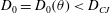 $D_{0}=D_{0}(\unicode[STIX]{x1D703})<D_{CJ}$
for fixed
$D_{0}=D_{0}(\unicode[STIX]{x1D703})<D_{CJ}$
for fixed
 $\unicode[STIX]{x1D6FD}$
.
$\unicode[STIX]{x1D6FD}$
.
3 Model
The detonation flow is governed by the non-dimensional 2D reactive Euler equations. These are written in conservative form as
 $$\begin{eqnarray}\frac{\unicode[STIX]{x2202}\boldsymbol{y}}{\unicode[STIX]{x2202}t}+\frac{\unicode[STIX]{x2202}\boldsymbol{f}_{\!\boldsymbol{r}}}{\unicode[STIX]{x2202}r}+\frac{\unicode[STIX]{x2202}\boldsymbol{f}_{\!\boldsymbol{z}}}{\unicode[STIX]{x2202}z}=\boldsymbol{g},\end{eqnarray}$$
where
 $$\begin{eqnarray}\displaystyle & \displaystyle \boldsymbol{y}=(\unicode[STIX]{x1D70C},\unicode[STIX]{x1D70C}u_{r},\unicode[STIX]{x1D70C}u_{z},\unicode[STIX]{x1D70C}E,\unicode[STIX]{x1D70C}\unicode[STIX]{x1D706})^{\text{T}},\quad \boldsymbol{f}_{\!\boldsymbol{r}}=(\unicode[STIX]{x1D70C}u_{r},\unicode[STIX]{x1D70C}u_{r}^{2}+p,\unicode[STIX]{x1D70C}u_{r}u_{z},u_{r}(\unicode[STIX]{x1D70C}E+p),\unicode[STIX]{x1D70C}u_{r}\unicode[STIX]{x1D706})^{\text{T}},\qquad & \displaystyle\end{eqnarray}$$
 $$\begin{eqnarray}\displaystyle & \displaystyle \boldsymbol{f}_{\!\boldsymbol{z}}=(\unicode[STIX]{x1D70C}u_{z},\unicode[STIX]{x1D70C}u_{r}u_{z},\unicode[STIX]{x1D70C}u_{z}^{2}+p,u_{z}(\unicode[STIX]{x1D70C}E+p),\unicode[STIX]{x1D70C}u_{z}\unicode[STIX]{x1D706})^{\text{T}}, & \displaystyle\end{eqnarray}$$
 $$\begin{eqnarray}\displaystyle & \displaystyle \boldsymbol{g}=(-s\unicode[STIX]{x1D70C}u_{r}/r,-s\unicode[STIX]{x1D70C}u_{r}^{2}/r,-s\unicode[STIX]{x1D70C}u_{r}u_{z}/r,-su_{r}(\unicode[STIX]{x1D70C}E+p)/r,\unicode[STIX]{x1D70C}\unicode[STIX]{x1D6EC}-s\unicode[STIX]{x1D70C}u_{r}\unicode[STIX]{x1D706}/r)^{\text{T}}. & \displaystyle\end{eqnarray}$$
Here,
 $r$
and
$r$
and
 $z$
denote spatial coordinates perpendicular and parallel to the undeflected wall, respectively (figure 3
a), while
$z$
denote spatial coordinates perpendicular and parallel to the undeflected wall, respectively (figure 3
a), while
 $\unicode[STIX]{x1D70C}$
,
$\unicode[STIX]{x1D70C}$
,
 $\boldsymbol{u}$
,
$\boldsymbol{u}$
,
 $E$
and
$E$
and
 $p$
are the density, flow velocity vector, total energy and pressure, respectively. For the 2D flow being considered, the velocity vector
$p$
are the density, flow velocity vector, total energy and pressure, respectively. For the 2D flow being considered, the velocity vector
 $\boldsymbol{u}=(u_{r},u_{z})^{\text{T}}$
. The reaction progress variable,
$\boldsymbol{u}=(u_{r},u_{z})^{\text{T}}$
. The reaction progress variable,
 $\unicode[STIX]{x1D706}\in [0,1]$
, tracks the conversion of reactants
$\unicode[STIX]{x1D706}\in [0,1]$
, tracks the conversion of reactants
 $(\unicode[STIX]{x1D706}=0)$
to products
$(\unicode[STIX]{x1D706}=0)$
to products
 $(\unicode[STIX]{x1D706}=1)$
. The symmetry parameter
$(\unicode[STIX]{x1D706}=1)$
. The symmetry parameter
 $s=0$
for the planar geometry, while
$s=0$
for the planar geometry, while
 $s=1$
for the cylinder geometry. The total energy is given by
$s=1$
for the cylinder geometry. The total energy is given by
 $$\begin{eqnarray}E=e(\unicode[STIX]{x1D70C},p,\unicode[STIX]{x1D706})+{\textstyle \frac{1}{2}}(u_{r}^{2}+u_{z}^{2}).\end{eqnarray}$$
We adopt the ideal condensed-phase detonation model (Short et al.
Reference Short, Anguelova, Aslam, Bdzil, Henrick and Sharpe2008), where the equation-of-state model for the internal energy
 $e$
and frozen sound speed
$e$
and frozen sound speed
 $c$
is given by
$c$
is given by
 $$\begin{eqnarray}e=\frac{p}{(\unicode[STIX]{x1D6FE}-1)\unicode[STIX]{x1D70C}}-q\unicode[STIX]{x1D706},\quad c=\left[\frac{\unicode[STIX]{x1D6FE}p}{\unicode[STIX]{x1D70C}}\right]^{1/2},\end{eqnarray}$$
where
 $\unicode[STIX]{x1D6FE}$
is the adiabatic exponent and
$\unicode[STIX]{x1D6FE}$
is the adiabatic exponent and
 $q$
is the specific reaction enthalpy of the reactant HE. In the strong shock limit (Short et al.
Reference Short, Quirk, Chiquete and Meyer2018), the pressure in the ambient HE state is zero, so that
$q$
is the specific reaction enthalpy of the reactant HE. In the strong shock limit (Short et al.
Reference Short, Quirk, Chiquete and Meyer2018), the pressure in the ambient HE state is zero, so that
 $$\begin{eqnarray}q=\frac{D_{CJ}^{2}}{2(\unicode[STIX]{x1D6FE}^{2}-1)},\end{eqnarray}$$
where
 $\unicode[STIX]{x1D70C}_{0}$
is the initial density of the HE. The reaction rate
$\unicode[STIX]{x1D70C}_{0}$
is the initial density of the HE. The reaction rate
 $\unicode[STIX]{x1D6EC}$
is pressure-dependent and given by (Short et al.
Reference Short, Quirk, Chiquete and Meyer2018)
$\unicode[STIX]{x1D6EC}$
is pressure-dependent and given by (Short et al.
Reference Short, Quirk, Chiquete and Meyer2018)
 $$\begin{eqnarray}\unicode[STIX]{x1D6EC}=kp(1-\unicode[STIX]{x1D706})^{1/2},\end{eqnarray}$$
where
 $k$
is a rate constant. Variations of this model have been explored by Bdzil (Reference Bdzil1981), Sharpe & Braithwaite (Reference Sharpe and Braithwaite2005), Short et al. (Reference Short, Quirk, Chiquete and Meyer2018) and Short & Quirk (Reference Short and Quirk2018a
,Reference Short and Quirk
b
) to study the flow physics of a variety of detonation confinement problems, and have been shown to capture the primary detonation flow physics present for more complex equation-of-state and reaction-rate models. The detonation shock conditions are
$k$
is a rate constant. Variations of this model have been explored by Bdzil (Reference Bdzil1981), Sharpe & Braithwaite (Reference Sharpe and Braithwaite2005), Short et al. (Reference Short, Quirk, Chiquete and Meyer2018) and Short & Quirk (Reference Short and Quirk2018a
,Reference Short and Quirk
b
) to study the flow physics of a variety of detonation confinement problems, and have been shown to capture the primary detonation flow physics present for more complex equation-of-state and reaction-rate models. The detonation shock conditions are
 $$\begin{eqnarray}\left.\begin{array}{@{}c@{}}\unicode[STIX]{x1D70C}_{s}(u_{n,s}-D_{ns})=-\unicode[STIX]{x1D70C}_{0}D_{ns},\quad p_{s}=\unicode[STIX]{x1D70C}_{0}^{2}D_{ns}^{2}\displaystyle \left(\frac{1}{\unicode[STIX]{x1D70C}_{0}}-\frac{1}{\unicode[STIX]{x1D70C}_{s}}\right),\\ e_{s}-e_{0}=\displaystyle \frac{1}{2}p_{s}\left(\frac{1}{\unicode[STIX]{x1D70C}_{0}}-\frac{1}{\unicode[STIX]{x1D70C}_{s}}\right),\quad \unicode[STIX]{x1D706}_{s}=0,\quad u_{t,s}=0,\end{array}\right\}\end{eqnarray}$$
where
 $u_{t}$
and
$u_{t}$
and
 $u_{n}$
are the tangent and normal flow velocities at the shock.
$u_{n}$
are the tangent and normal flow velocities at the shock.
3.1 Scaling
The non-dimensional scaling employed above is the same as that used by Short et al. (Reference Short, Quirk, Chiquete and Meyer2018) and given by
 $$\begin{eqnarray}\left.\begin{array}{@{}c@{}}\displaystyle (r,z)=\frac{(\tilde{r},\tilde{z})}{\tilde{l}_{1/2}},\quad t=\frac{\tilde{t}}{(\tilde{l}_{1/2}/\tilde{u} _{ref})},\quad \unicode[STIX]{x1D70C}=\frac{\tilde{\unicode[STIX]{x1D70C}}}{\tilde{\unicode[STIX]{x1D70C}}_{ref}},\quad \boldsymbol{u}=\frac{\tilde{\boldsymbol{u}}}{\tilde{u} _{ref}},\quad p=\frac{\tilde{p}}{\tilde{\unicode[STIX]{x1D70C}}_{ref}\tilde{u} _{ref}^{2}},\quad e=\frac{\tilde{e}}{\tilde{u} _{ref}^{2}},\\ \displaystyle q=\frac{\tilde{q}}{\tilde{u} _{ref}^{2}},\quad D_{CJ}=\frac{\tilde{D}_{CJ}}{\tilde{u} _{ref}},\quad c=\frac{\tilde{c}}{\tilde{u} _{ref}},\quad k=\tilde{k}\tilde{\unicode[STIX]{x1D70C}}_{ref}\tilde{u} _{ref}\tilde{l}_{1/2},\end{array}\right\}\end{eqnarray}$$
where
 $\tilde{\{~\}}$
quantities are dimensional. Here,
$\tilde{\{~\}}$
quantities are dimensional. Here,
 $\tilde{l}_{1/2}$
is the length behind the shock in the steady planar Chapman–Jouguet detonation wave at which half of the reactant has been consumed. We make the reference scaling choices (Short et al.
Reference Short, Quirk, Chiquete and Meyer2018),
$\tilde{l}_{1/2}$
is the length behind the shock in the steady planar Chapman–Jouguet detonation wave at which half of the reactant has been consumed. We make the reference scaling choices (Short et al.
Reference Short, Quirk, Chiquete and Meyer2018),
 $$\begin{eqnarray}\unicode[STIX]{x1D70C}_{0}=\frac{\tilde{\unicode[STIX]{x1D70C}}_{0}}{\tilde{\unicode[STIX]{x1D70C}}_{ref}}=2,\quad D_{CJ}=\frac{\tilde{D}_{CJ}}{\tilde{u} _{ref}}=8,\end{eqnarray}$$
where
 $\tilde{\unicode[STIX]{x1D70C}}_{0}$
is the dimensional initial density of the HE and
$\tilde{\unicode[STIX]{x1D70C}}_{0}$
is the dimensional initial density of the HE and
 $\tilde{D}_{CJ}$
is the corresponding dimensional Chapman–Jouguet detonation speed. By varying the reference choices
$\tilde{D}_{CJ}$
is the corresponding dimensional Chapman–Jouguet detonation speed. By varying the reference choices
 $\tilde{\unicode[STIX]{x1D70C}}_{ref}$
and
$\tilde{\unicode[STIX]{x1D70C}}_{ref}$
and
 $\tilde{u} _{ref},$
this formulation can be used to mimic a range of explosive classes. As noted in Short et al. (Reference Short, Quirk, Chiquete and Meyer2018), a density scale
$\tilde{u} _{ref},$
this formulation can be used to mimic a range of explosive classes. As noted in Short et al. (Reference Short, Quirk, Chiquete and Meyer2018), a density scale
 $\tilde{\unicode[STIX]{x1D70C}}_{ref}=1~\text{g}~\text{cm}^{-3}$
and velocity scale
$\tilde{\unicode[STIX]{x1D70C}}_{ref}=1~\text{g}~\text{cm}^{-3}$
and velocity scale
 $\tilde{u} _{ref}=1~\text{mm}~\unicode[STIX]{x03BC}\text{s}^{-1}$
would be broadly representative of the properties of a conventional or insensitive high explosive, such as PBX 9502.
$\tilde{u} _{ref}=1~\text{mm}~\unicode[STIX]{x03BC}\text{s}^{-1}$
would be broadly representative of the properties of a conventional or insensitive high explosive, such as PBX 9502.
3.2 Fitted coordinate calculation
To study the confinement effect on the detonation structure due to the wall-boundary deflection, we adopt a shock and wall-boundary-fitted formulation for 2D flows (Henrick Reference Henrick2008; Romick & Aslam Reference Romick and Aslam2017). The coordinates
 $r$
and
$r$
and
 $z$
are transformed according to
$z$
are transformed according to
 $$\begin{eqnarray}r(\unicode[STIX]{x1D709},\unicode[STIX]{x1D702},\unicode[STIX]{x1D70F})=\left(1-\frac{m(\unicode[STIX]{x1D70F})\unicode[STIX]{x1D702}}{\unicode[STIX]{x1D6FD}}\right)\unicode[STIX]{x1D709},\quad z(\unicode[STIX]{x1D709},\unicode[STIX]{x1D702},\unicode[STIX]{x1D70F})=z_{s}(\unicode[STIX]{x1D709},\unicode[STIX]{x1D70F})+\unicode[STIX]{x1D702},\quad t=\unicode[STIX]{x1D70F},\end{eqnarray}$$
where
 $m(\unicode[STIX]{x1D70F})=\tan \unicode[STIX]{x1D703}(\unicode[STIX]{x1D70F})$
and
$m(\unicode[STIX]{x1D70F})=\tan \unicode[STIX]{x1D703}(\unicode[STIX]{x1D70F})$
and
 $\unicode[STIX]{x1D6FD}=T/2$
(planar) or
$\unicode[STIX]{x1D6FD}=T/2$
(planar) or
 $\unicode[STIX]{x1D6FD}=R$
(cylindrical). This generates the rectilinear coordinate system shown in figure 3(b), where
$\unicode[STIX]{x1D6FD}=R$
(cylindrical). This generates the rectilinear coordinate system shown in figure 3(b), where
 $\unicode[STIX]{x1D702}=0$
is the transformed shock position,
$\unicode[STIX]{x1D702}=0$
is the transformed shock position,
 $z=z_{s}(\unicode[STIX]{x1D709},\unicode[STIX]{x1D70F})$
describes the shock shape evolution,
$z=z_{s}(\unicode[STIX]{x1D709},\unicode[STIX]{x1D70F})$
describes the shock shape evolution,
 $\unicode[STIX]{x1D709}=\unicode[STIX]{x1D6FD}$
is the location of the deflected wall boundary and
$\unicode[STIX]{x1D709}=\unicode[STIX]{x1D6FD}$
is the location of the deflected wall boundary and
 $\unicode[STIX]{x1D709}=0$
represents the axis of symmetry. Under the transformation (3.12), the flow equations (3.1) become
$\unicode[STIX]{x1D709}=0$
represents the axis of symmetry. Under the transformation (3.12), the flow equations (3.1) become
 $$\begin{eqnarray}\frac{\unicode[STIX]{x2202}\boldsymbol{Y}}{\unicode[STIX]{x2202}\unicode[STIX]{x1D70F}}+\frac{\unicode[STIX]{x2202}\boldsymbol{F}_{\!\unicode[STIX]{x1D743}}}{\unicode[STIX]{x2202}\unicode[STIX]{x1D709}}+\frac{\unicode[STIX]{x2202}\boldsymbol{F}_{\!\boldsymbol{\unicode[STIX]{x1D702}}}}{\unicode[STIX]{x2202}\unicode[STIX]{x1D702}}=\boldsymbol{G},\end{eqnarray}$$
where
 $$\begin{eqnarray}\boldsymbol{Y}=|J|\boldsymbol{y},\quad \boldsymbol{F}_{\!\unicode[STIX]{x1D743}}=\phantom{-}\frac{\unicode[STIX]{x2202}z}{\unicode[STIX]{x2202}\unicode[STIX]{x1D702}}\left(\boldsymbol{f}_{\!\boldsymbol{r}}-\frac{\unicode[STIX]{x2202}r}{\unicode[STIX]{x2202}\unicode[STIX]{x1D70F}}\boldsymbol{y}\right)-\frac{\unicode[STIX]{x2202}r}{\unicode[STIX]{x2202}\unicode[STIX]{x1D702}}\left(\boldsymbol{f}_{\!\boldsymbol{z}}-\frac{\unicode[STIX]{x2202}z}{\unicode[STIX]{x2202}\unicode[STIX]{x1D70F}}\boldsymbol{y}\right),\end{eqnarray}$$
 $$\begin{eqnarray}\boldsymbol{F}_{\!\unicode[STIX]{x1D702}}=-\frac{\unicode[STIX]{x2202}z}{\unicode[STIX]{x2202}\unicode[STIX]{x1D709}}\left(\boldsymbol{f}_{\!\boldsymbol{r}}-\frac{\unicode[STIX]{x2202}r}{\unicode[STIX]{x2202}\unicode[STIX]{x1D70F}}\boldsymbol{y}\right)+\frac{\unicode[STIX]{x2202}r}{\unicode[STIX]{x2202}\unicode[STIX]{x1D709}}\left(\boldsymbol{f}_{\!\boldsymbol{z}}-\frac{\unicode[STIX]{x2202}z}{\unicode[STIX]{x2202}\unicode[STIX]{x1D70F}}\boldsymbol{y}\right),\quad \boldsymbol{G}=|J|\boldsymbol{g},\quad |J|=\frac{\unicode[STIX]{x2202}r}{\unicode[STIX]{x2202}\unicode[STIX]{x1D709}}\frac{\unicode[STIX]{x2202}z}{\unicode[STIX]{x2202}\unicode[STIX]{x1D702}}-\frac{\unicode[STIX]{x2202}r}{\unicode[STIX]{x2202}\unicode[STIX]{x1D702}}\frac{\unicode[STIX]{x2202}z}{\unicode[STIX]{x2202}\unicode[STIX]{x1D709}},\end{eqnarray}$$
and
 $$\begin{eqnarray}\displaystyle \frac{\unicode[STIX]{x2202}r}{\unicode[STIX]{x2202}\unicode[STIX]{x1D702}}=-\frac{\unicode[STIX]{x1D709}m(\unicode[STIX]{x1D70F})}{\unicode[STIX]{x1D6FD}},\quad \displaystyle \frac{\unicode[STIX]{x2202}z}{\unicode[STIX]{x2202}\unicode[STIX]{x1D702}}=1,\quad \displaystyle \frac{\unicode[STIX]{x2202}r}{\unicode[STIX]{x2202}\unicode[STIX]{x1D70F}}=-\displaystyle \frac{\unicode[STIX]{x1D709}\unicode[STIX]{x1D702}}{\unicode[STIX]{x1D6FD}}\displaystyle \frac{\text{d}m}{\text{d}\unicode[STIX]{x1D70F}},\quad \displaystyle \frac{\unicode[STIX]{x2202}z}{\unicode[STIX]{x2202}\unicode[STIX]{x1D70F}}=\displaystyle \frac{\unicode[STIX]{x2202}z_{s}}{\unicode[STIX]{x2202}\unicode[STIX]{x1D70F}},\end{eqnarray}$$
 $$\begin{eqnarray}\displaystyle \frac{\unicode[STIX]{x2202}z}{\unicode[STIX]{x2202}\unicode[STIX]{x1D709}}=\displaystyle \frac{\unicode[STIX]{x2202}z_{s}}{\unicode[STIX]{x2202}\unicode[STIX]{x1D709}},\quad \displaystyle \frac{\unicode[STIX]{x2202}r}{\unicode[STIX]{x2202}\unicode[STIX]{x1D709}}=1-\frac{m(\unicode[STIX]{x1D70F})\unicode[STIX]{x1D702}}{\unicode[STIX]{x1D6FD}},\end{eqnarray}$$
 $$\begin{eqnarray}|J|=1-\displaystyle \frac{m(\unicode[STIX]{x1D70F})\unicode[STIX]{x1D702}}{\unicode[STIX]{x1D6FD}}+\displaystyle \frac{\unicode[STIX]{x1D709}m(\unicode[STIX]{x1D70F})}{\unicode[STIX]{x1D6FD}}\displaystyle \frac{\unicode[STIX]{x2202}z_{s}}{\unicode[STIX]{x2202}\unicode[STIX]{x1D709}},\quad \displaystyle \frac{\unicode[STIX]{x2202}|J|}{\unicode[STIX]{x2202}\unicode[STIX]{x1D70F}}=\left(\displaystyle \frac{\unicode[STIX]{x1D709}}{\unicode[STIX]{x1D6FD}}\displaystyle \frac{\unicode[STIX]{x2202}z_{s}}{\unicode[STIX]{x2202}\unicode[STIX]{x1D709}}-\displaystyle \frac{\unicode[STIX]{x1D702}}{\unicode[STIX]{x1D6FD}}\right)\displaystyle \frac{\unicode[STIX]{x2202}m}{\unicode[STIX]{x2202}\unicode[STIX]{x1D70F}}+\displaystyle \frac{m(\unicode[STIX]{x1D70F})\unicode[STIX]{x1D709}}{\unicode[STIX]{x1D6FD}}\displaystyle \frac{\unicode[STIX]{x2202}}{\unicode[STIX]{x2202}\unicode[STIX]{x1D70F}}\left(\displaystyle \frac{\unicode[STIX]{x2202}z_{s}}{\unicode[STIX]{x2202}\unicode[STIX]{x1D709}}\right).\end{eqnarray}$$
The transformation requires the evaluation of
 $\unicode[STIX]{x2202}z_{s}/\unicode[STIX]{x2202}\unicode[STIX]{x1D70F}$
and
$\unicode[STIX]{x2202}z_{s}/\unicode[STIX]{x2202}\unicode[STIX]{x1D70F}$
and
 $\unicode[STIX]{x2202}z_{s}/\unicode[STIX]{x2202}\unicode[STIX]{x1D709}$
. These are obtained through the shock surface evolution equations,
$\unicode[STIX]{x2202}z_{s}/\unicode[STIX]{x2202}\unicode[STIX]{x1D709}$
. These are obtained through the shock surface evolution equations,
 $$\begin{eqnarray}\frac{\unicode[STIX]{x2202}z_{s}}{\unicode[STIX]{x2202}\unicode[STIX]{x1D70F}}=D_{ns}\sqrt{\left(\displaystyle \frac{\unicode[STIX]{x2202}z_{s}}{\unicode[STIX]{x2202}\unicode[STIX]{x1D709}}\right)^{2}+1},\quad \frac{\unicode[STIX]{x2202}}{\unicode[STIX]{x2202}\unicode[STIX]{x1D70F}}\left(\frac{\unicode[STIX]{x2202}z_{s}}{\unicode[STIX]{x2202}\unicode[STIX]{x1D709}}\right)=\frac{\unicode[STIX]{x2202}}{\unicode[STIX]{x2202}\unicode[STIX]{x1D709}}\left(D_{ns}\sqrt{\left(\displaystyle \frac{\unicode[STIX]{x2202}z_{s}}{\unicode[STIX]{x2202}\unicode[STIX]{x1D709}}\right)^{2}+1}\right),\end{eqnarray}$$
where
 $D_{ns}=D_{ns}(\unicode[STIX]{x1D709},\unicode[STIX]{x1D70F})$
is the local normal speed of the shock. An evolution equation for
$D_{ns}=D_{ns}(\unicode[STIX]{x1D709},\unicode[STIX]{x1D70F})$
is the local normal speed of the shock. An evolution equation for
 $D_{ns}$
can be constructed from the shock conditions (3.9) using the total energy solution element
$D_{ns}$
can be constructed from the shock conditions (3.9) using the total energy solution element
 $(\unicode[STIX]{x1D70C}E)$
. After differentiating, it follows that
$(\unicode[STIX]{x1D70C}E)$
. After differentiating, it follows that
 $$\begin{eqnarray}\frac{\unicode[STIX]{x2202}D_{ns}}{\unicode[STIX]{x2202}\unicode[STIX]{x1D70F}}=\frac{\text{d}(\unicode[STIX]{x1D70C}_{s}E_{s})}{\text{d}D_{ns}}\left(\boldsymbol{G}-\frac{\unicode[STIX]{x2202}\boldsymbol{F}_{\!\unicode[STIX]{x1D743}}}{\unicode[STIX]{x2202}\unicode[STIX]{x1D709}}-\frac{\unicode[STIX]{x2202}\boldsymbol{F}_{\!\boldsymbol{\unicode[STIX]{x1D702}}}}{\unicode[STIX]{x2202}\unicode[STIX]{x1D702}}\right)\bigg|_{s}.\end{eqnarray}$$
Boundary conditions are as follows. Symmetry conditions are applied along the central axis (
 $\unicode[STIX]{x1D709}=0$
), reflection boundary conditions (no normal flow) are applied along the wall (
$\unicode[STIX]{x1D709}=0$
), reflection boundary conditions (no normal flow) are applied along the wall (
 $\unicode[STIX]{x1D709}=\unicode[STIX]{x1D6FD}$
), while along the shock front, the flow solution is determined from the jump conditions (3.9) as a function of
$\unicode[STIX]{x1D709}=\unicode[STIX]{x1D6FD}$
), while along the shock front, the flow solution is determined from the jump conditions (3.9) as a function of
 $D_{ns}.$
This gives
$D_{ns}.$
This gives
 $$\begin{eqnarray}\boldsymbol{F}_{\!\unicode[STIX]{x1D743}}(0,\unicode[STIX]{x1D702})=\left(0,p,0,0,0,0\right)^{\text{T}},\quad \boldsymbol{F}_{\!\unicode[STIX]{x1D743}}(\unicode[STIX]{x1D6FD},\unicode[STIX]{x1D702})=p\left(0,1,m(\unicode[STIX]{x1D70F}),-\unicode[STIX]{x1D702}\frac{\text{d}m}{\text{d}\unicode[STIX]{x1D70F}}+m(\unicode[STIX]{x1D70F})\frac{\unicode[STIX]{x2202}z_{s}}{\unicode[STIX]{x2202}\unicode[STIX]{x1D70F}},0,0\right)^{\text{T}},\end{eqnarray}$$
 $$\begin{eqnarray}\boldsymbol{F}_{\!\boldsymbol{\unicode[STIX]{x1D702}}}(\unicode[STIX]{x1D709},0)=-\frac{\unicode[STIX]{x2202}z_{s}}{\unicode[STIX]{x2202}\unicode[STIX]{x1D709}}\boldsymbol{f}_{\!\boldsymbol{r}}\bigg|_{s}+\boldsymbol{f}_{\!\boldsymbol{z}}\bigg|_{s}-\frac{\unicode[STIX]{x2202}z_{s}}{\unicode[STIX]{x2202}\unicode[STIX]{x1D70F}}\boldsymbol{y}\bigg|_{s}.\end{eqnarray}$$
The flow solution at the outflow boundary
 $\unicode[STIX]{x1D702}=\unicode[STIX]{x1D702}_{out}$
is extrapolated linearly from the interior.
$\unicode[STIX]{x1D702}=\unicode[STIX]{x1D702}_{out}$
is extrapolated linearly from the interior.
The initial conditions consist of the one-dimensional planar Zeldovich–von Neumann–Döring detonation wave solution (Short et al.
Reference Short, Quirk, Chiquete and Meyer2018) imposed in the
 $(\unicode[STIX]{x1D709},\unicode[STIX]{x1D702})$
field with no initial wall deflection (
$(\unicode[STIX]{x1D709},\unicode[STIX]{x1D702})$
field with no initial wall deflection (
 $\unicode[STIX]{x1D703}=0\;\Longrightarrow \;m(\unicode[STIX]{x1D70F}=0)=0$
). The wall deflection angle is then increased in time according to the
$\unicode[STIX]{x1D703}=0\;\Longrightarrow \;m(\unicode[STIX]{x1D70F}=0)=0$
). The wall deflection angle is then increased in time according to the
 $m(\unicode[STIX]{x1D70F})$
prescription,
$m(\unicode[STIX]{x1D70F})$
prescription,
 $$\begin{eqnarray}m(\unicode[STIX]{x1D70F})=\left\{\begin{array}{@{}ll@{}}0,\quad & \unicode[STIX]{x1D70F}\leqslant \unicode[STIX]{x1D70F}_{c},\\ \frac{1}{2}m_{e}(1-\cos (\unicode[STIX]{x03C0}(\unicode[STIX]{x1D70F}-\unicode[STIX]{x1D70F}_{c})/\unicode[STIX]{x1D70F}_{b})),\quad & \unicode[STIX]{x1D70F}_{c}<\unicode[STIX]{x1D70F}<\unicode[STIX]{x1D70F}_{c}+\unicode[STIX]{x1D70F}_{b},\\ m_{e},\quad & \unicode[STIX]{x1D70F}\geqslant \unicode[STIX]{x1D70F}_{c}+\unicode[STIX]{x1D70F}_{b},\end{array}\right.\end{eqnarray}$$
until the desired wall deflection angle
 $\unicode[STIX]{x1D703}$
is reached, where
$\unicode[STIX]{x1D703}$
is reached, where
 $m_{e}=\tan \unicode[STIX]{x1D703}.$
Thereafter the detonation is allowed to relax to the steady-state solution corresponding to the imposed wall deflection angle
$m_{e}=\tan \unicode[STIX]{x1D703}.$
Thereafter the detonation is allowed to relax to the steady-state solution corresponding to the imposed wall deflection angle
 $\unicode[STIX]{x1D703}.$
We use
$\unicode[STIX]{x1D703}.$
We use
 $\unicode[STIX]{x1D70F}_{b}=2.5$
and
$\unicode[STIX]{x1D70F}_{b}=2.5$
and
 $\unicode[STIX]{x1D70F}_{c}=20$
for the results shown below.
$\unicode[STIX]{x1D70F}_{c}=20$
for the results shown below.
The above system is integrated used a finite-volume approach, second order in time and space, with spatial discretization by a Lax–Friedrichs flux-splitting method with centred minmod limiting. A two-stage, second-order Heun’s method is used to update the shock slope (3.19), normal shock speed (3.20) and interior solution vector (3.13). The convergence properties of this algorithm have been extensively studied for detonation flows (e.g. Chiquete et al.
Reference Chiquete, Short, Meyer and Quirk2018a
). Most of the simulations shown below use either 64 or 128 points per unit length (scaled to be the length over which the steady planar Chapman–Jouguet detonation wave has consumed half of the reactants). This resolution was required to resolve the path of the characteristics in the HE supersonic flow region, especially in the vicinity of the sonic line. Flow solutions obtained in the shock and wall-boundary-attached system
 $(\unicode[STIX]{x1D709},\unicode[STIX]{x1D702})$
are then transformed back into the laboratory frame
$(\unicode[STIX]{x1D709},\unicode[STIX]{x1D702})$
are then transformed back into the laboratory frame
 $(r,z)$
for presentation of results (§ 6).
$(r,z)$
for presentation of results (§ 6).

Figure 4. Shock polar analysis for (a) strong confinement and (b) weak confinement configurations.
4 Shock polar theory
Figure 4 shows a schematic of the oblique-shock polar analysis relevant to strong and weak confinement cases for a deflected wall boundary in the vicinity of the wall. In both cases, an oblique shock travels with a specified phase speed
 $D_{0}$
in the direction of the undeflected wall, with incident angle given by
$D_{0}$
in the direction of the undeflected wall, with incident angle given by
 $w.$
The flow state behind the shock is determined by the solution of
$w.$
The flow state behind the shock is determined by the solution of
 $$\begin{eqnarray}\left.\begin{array}{@{}c@{}}\displaystyle u_{n}=D_{0}\sin w\left(1-\frac{\unicode[STIX]{x1D70C}_{0}}{\unicode[STIX]{x1D70C}}\right),~p=\unicode[STIX]{x1D70C}_{0}D_{0}^{2}\sin ^{2}w\left(1-\frac{\unicode[STIX]{x1D70C}_{0}}{\unicode[STIX]{x1D70C}}\right),\\ \displaystyle e-e_{0}+\frac{1}{2}p\left(\frac{1}{\unicode[STIX]{x1D70C}}-\frac{1}{\unicode[STIX]{x1D70C}_{0}}\right)=0,\end{array}\right\}\end{eqnarray}$$
where
 $$\begin{eqnarray}u_{z}=u_{n}\sin (w),\quad u_{r}=u_{n}\cos (w).\end{eqnarray}$$
The resulting streamline turning angle
 $\unicode[STIX]{x1D703}$
, equivalent to the wall deflection angle, and Mach number
$\unicode[STIX]{x1D703}$
, equivalent to the wall deflection angle, and Mach number
 $M$
of the post-shock state are
$M$
of the post-shock state are
 $$\begin{eqnarray}\unicode[STIX]{x1D703}=\tan ^{-1}\left(\frac{u_{r}}{D_{0}-u_{z}}\right),\quad M=\frac{\sqrt{(D_{0}-u_{z})^{2}+u_{r}^{2}}}{c}.\end{eqnarray}$$
This allows the shock pressure to be calculated as a function of
 $\unicode[STIX]{x1D703}$
up to the maximum streamline turning angle
$\unicode[STIX]{x1D703}$
up to the maximum streamline turning angle
 $\unicode[STIX]{x1D703}_{m}.$
For the ideal condensed-phase model, the streamline turning angle corresponding to sonic flow in the post-shock state
$\unicode[STIX]{x1D703}_{m}.$
For the ideal condensed-phase model, the streamline turning angle corresponding to sonic flow in the post-shock state
 $(\unicode[STIX]{x1D703}_{s})$
is independent of
$(\unicode[STIX]{x1D703}_{s})$
is independent of
 $D_{0}$
and equal to
$D_{0}$
and equal to
 $\unicode[STIX]{x1D703}_{m},$
where
$\unicode[STIX]{x1D703}_{m},$
where
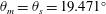 $\unicode[STIX]{x1D703}_{m}=\unicode[STIX]{x1D703}_{s}=19.471^{\circ }$
(Short & Quirk Reference Short and Quirk2018b
). The shock polar flow structure for strong confinement is shown schematically in figure 4(a) and occurs for
$\unicode[STIX]{x1D703}_{m}=\unicode[STIX]{x1D703}_{s}=19.471^{\circ }$
(Short & Quirk Reference Short and Quirk2018b
). The shock polar flow structure for strong confinement is shown schematically in figure 4(a) and occurs for
 $\unicode[STIX]{x1D703}<\unicode[STIX]{x1D703}_{m}=\unicode[STIX]{x1D703}_{s}.$
Figure 5 shows the oblique-shock polar solutions for strong confinement for two phase speeds
$\unicode[STIX]{x1D703}<\unicode[STIX]{x1D703}_{m}=\unicode[STIX]{x1D703}_{s}.$
Figure 5 shows the oblique-shock polar solutions for strong confinement for two phase speeds
 $D_{0}=5.5$
and
$D_{0}=5.5$
and
 $D_{0}=7.5$
, where the relevant strong confinement solutions lie on the subsonic branch of the polar. For the wall deflection problem, for a given phase speed
$D_{0}=7.5$
, where the relevant strong confinement solutions lie on the subsonic branch of the polar. For the wall deflection problem, for a given phase speed
 $D_{0},$
the streamline turning angle is set equal to the specified wall deflection angle and the corresponding shock pressure can be calculated, as in figure 5.
$D_{0},$
the streamline turning angle is set equal to the specified wall deflection angle and the corresponding shock pressure can be calculated, as in figure 5.

Figure 5. Oblique wave polar solutions for the phase speeds
 $D_{0}$
indicated. The circles (SP) represent the post-shock sonic flow state. The PM fan solutions which originate out of the sonic flow state, and along which the flow is increasingly supersonic, are indicated by the dashed lines.
$D_{0}$
indicated. The circles (SP) represent the post-shock sonic flow state. The PM fan solutions which originate out of the sonic flow state, and along which the flow is increasingly supersonic, are indicated by the dashed lines.
The shock polar structure for weak confinement is shown in figure 4(b) and occurs when the wall deflection angle
 $\unicode[STIX]{x1D703}>\unicode[STIX]{x1D703}_{m}=\unicode[STIX]{x1D703}_{s}.$
A PM fan is then required to achieve streamline turning angles equal to the deflected wall turning angle. The PM fan is centred at the intersection of the shock and wall, and connects the post-shock solution which gives sonic flow to the deflection angle of the wall. Transforming to polar coordinates, where
$\unicode[STIX]{x1D703}>\unicode[STIX]{x1D703}_{m}=\unicode[STIX]{x1D703}_{s}.$
A PM fan is then required to achieve streamline turning angles equal to the deflected wall turning angle. The PM fan is centred at the intersection of the shock and wall, and connects the post-shock solution which gives sonic flow to the deflection angle of the wall. Transforming to polar coordinates, where
 $\unicode[STIX]{x1D719}$
is the polar angle coordinate and
$\unicode[STIX]{x1D719}$
is the polar angle coordinate and
 $U_{r}$
and
$U_{r}$
and
 $U_{\unicode[STIX]{x1D719}}$
are the radial and polar angle linear speeds, respectively, in a frame travelling in the
$U_{\unicode[STIX]{x1D719}}$
are the radial and polar angle linear speeds, respectively, in a frame travelling in the
 $z$
direction at speed
$z$
direction at speed
 $D_{0}$
(figure 4
b), the PM fan state is determined by solution of
$D_{0}$
(figure 4
b), the PM fan state is determined by solution of
 $$\begin{eqnarray}\frac{\text{d}p}{\text{d}\unicode[STIX]{x1D719}}=c^{2}\frac{\text{d}\unicode[STIX]{x1D70C}}{\text{d}\unicode[STIX]{x1D719}},\quad \frac{\text{d}U_{r}}{\text{d}\unicode[STIX]{x1D719}}=U_{\unicode[STIX]{x1D719}},\quad U_{\unicode[STIX]{x1D719}}=c,\quad e-e_{0}+\frac{p}{\unicode[STIX]{x1D70C}}+\frac{1}{2}(U_{r}^{2}+U_{\unicode[STIX]{x1D719}}^{2})=\frac{D_{0}^{2}}{2}.\end{eqnarray}$$
The PM fan wavehead lies along the polar angle coordinate determined from
 $$\begin{eqnarray}-\text{sin}(\unicode[STIX]{x1D719})u_{r}+\cos (\unicode[STIX]{x1D719})(u_{z}-D_{0})=c,\end{eqnarray}$$
where
 $U_{r}=0$
along the wavehead. The streamline turning angle and Mach number through the PM fan are given by (4.3), where
$U_{r}=0$
along the wavehead. The streamline turning angle and Mach number through the PM fan are given by (4.3), where
 $$\begin{eqnarray}u_{r}=U_{r}\cos \unicode[STIX]{x1D719}-U_{\unicode[STIX]{x1D719}}\sin \unicode[STIX]{x1D719},\quad u_{z}=U_{r}\sin \unicode[STIX]{x1D719}+U_{\unicode[STIX]{x1D719}}\cos \unicode[STIX]{x1D719}+D_{0}.\end{eqnarray}$$
The tail of the PM fan lies at an angle
 $\unicode[STIX]{x1D719}$
where the flow has been turned through the specified wall deflection angle
$\unicode[STIX]{x1D719}$
where the flow has been turned through the specified wall deflection angle
 $\unicode[STIX]{x1D703}.$
Figure 5 shows PM fan solutions for the two phase speeds
$\unicode[STIX]{x1D703}.$
Figure 5 shows PM fan solutions for the two phase speeds
 $D_{0}=5.5$
and
$D_{0}=5.5$
and
 $D_{0}=7.5$
. The PM fan solutions give the pressure on the deflected wall as a function of wall turning angle
$D_{0}=7.5$
. The PM fan solutions give the pressure on the deflected wall as a function of wall turning angle
 $\unicode[STIX]{x1D703}.$
5 Characteristics of the steady supersonic flow region
In the supersonic regions of the steady flow behind the sonic locus of the DDZ, the paths of the characteristics in the
 $(r,z)$
coordinate system (figure 3
a) are given by
$(r,z)$
coordinate system (figure 3
a) are given by
 $$\begin{eqnarray}\frac{\text{d}z}{\text{d}r}=\frac{(u_{z}-D_{0})^{2}-c^{2}}{(u_{z}-D_{0})u_{r}\pm c\sqrt{(u_{z}-D_{0})^{2}+u_{r}^{2}-c^{2}}}.\end{eqnarray}$$
The
 $+$
sign in the denominator of (5.1) is associated with
$+$
sign in the denominator of (5.1) is associated with
 $C^{+}$
characteristics that propagate information from right to left, while the
$C^{+}$
characteristics that propagate information from right to left, while the
 $-$
sign in (5.1) is associated with
$-$
sign in (5.1) is associated with
 $C^{-}$
characteristics propagating information from left to right (see § 6). On the sonic locus
$C^{-}$
characteristics propagating information from left to right (see § 6). On the sonic locus
 $(u_{z}-D_{0})^{2}+u_{r}^{2}=c^{2}$
, and thus
$(u_{z}-D_{0})^{2}+u_{r}^{2}=c^{2}$
, and thus
 $$\begin{eqnarray}\frac{\text{d}z}{\text{d}r}=-\frac{u_{r}}{u_{z}-D_{0}}\end{eqnarray}$$
for both the
 $C^{+}$
and
$C^{+}$
and
 $C^{-}$
characteristics, so that both characteristic families enter or leave the sonic locus with the same slope. The slope of the streamlines is given by
$C^{-}$
characteristics, so that both characteristic families enter or leave the sonic locus with the same slope. The slope of the streamlines is given by
 $$\begin{eqnarray}\frac{\text{d}z}{\text{d}r}=\frac{u_{z}-D_{0}}{u_{r}},\end{eqnarray}$$
which is normal to the
 $C^{+}$
and
$C^{+}$
and
 $C^{-}$
characteristics at the sonic line. On the HE symmetry axis,
$C^{-}$
characteristics at the sonic line. On the HE symmetry axis,
 $$\begin{eqnarray}\frac{\text{d}z}{\text{d}r}=\frac{(u_{z}-D_{0})^{2}-c^{2}}{\pm c\sqrt{(u_{z}-D_{0})^{2}-c^{2}}},\end{eqnarray}$$
so that
 $\text{d}z/\text{d}r=0$
on the sonic line at the HE symmetry axis for both the
$\text{d}z/\text{d}r=0$
on the sonic line at the HE symmetry axis for both the
 $C^{+}$
and
$C^{+}$
and
 $C^{-}$
characteristics.
$C^{-}$
characteristics.
6 Results
6.1 Planar geometry with
 $T=20$

Figure 6 shows the variation in steady detonation propagation phase speed
 $(D_{0})$
with wall deflection angle (
$(D_{0})$
with wall deflection angle (
 $\unicode[STIX]{x1D703}$
) for a planar geometry with thickness
$\unicode[STIX]{x1D703}$
) for a planar geometry with thickness
 $T=20.$
In the strong confinement regime,
$T=20.$
In the strong confinement regime,
 $D_{0}$
decreases monotonically with increasing
$D_{0}$
decreases monotonically with increasing
 $\unicode[STIX]{x1D703}$
. For a sufficiently large deflection angle (
$\unicode[STIX]{x1D703}$
. For a sufficiently large deflection angle (
 $\unicode[STIX]{x1D703}\approx 21.75^{\circ }$
), the phase speed approaches a limiting value whereupon further increases in
$\unicode[STIX]{x1D703}\approx 21.75^{\circ }$
), the phase speed approaches a limiting value whereupon further increases in
 $\unicode[STIX]{x1D703}$
do not influence the phase speed. We define this as the weak confinement regime (§ 1). There are two important properties of the phase speed variation that require further discussion. As discussed in § 4, the streamline deflection angle at which the flow behind the detonation shock becomes sonic
$\unicode[STIX]{x1D703}$
do not influence the phase speed. We define this as the weak confinement regime (§ 1). There are two important properties of the phase speed variation that require further discussion. As discussed in § 4, the streamline deflection angle at which the flow behind the detonation shock becomes sonic
 $(\unicode[STIX]{x1D703}_{s})$
is a constant for all
$(\unicode[STIX]{x1D703}_{s})$
is a constant for all
 $D_{0},$
i.e.
$D_{0},$
i.e.
 $\unicode[STIX]{x1D703}_{s}=19.471^{\circ }$
. However, in the wall deflection simulations (figure 6),
$\unicode[STIX]{x1D703}_{s}=19.471^{\circ }$
. However, in the wall deflection simulations (figure 6),
 $D_{0}$
continues to decrease beyond
$D_{0}$
continues to decrease beyond
 $\unicode[STIX]{x1D703}_{s}.$
Thus even though the flow at the intersection point of the detonation shock and wall is sonic, the non-local global DDZ structure still senses the presence of the strong confinement boundary. Sonic flow locally at the intersection point does not therefore imply that the DDZ structure is independent of the wall turning angle. Secondly, there is a distinct kink in the variation of
$\unicode[STIX]{x1D703}_{s}.$
Thus even though the flow at the intersection point of the detonation shock and wall is sonic, the non-local global DDZ structure still senses the presence of the strong confinement boundary. Sonic flow locally at the intersection point does not therefore imply that the DDZ structure is independent of the wall turning angle. Secondly, there is a distinct kink in the variation of
 $D_{0}$
with
$D_{0}$
with
 $\unicode[STIX]{x1D703}$
near the transition from strong to weak confinement regimes, as shown in the inset of figure 6, commencing around
$\unicode[STIX]{x1D703}$
near the transition from strong to weak confinement regimes, as shown in the inset of figure 6, commencing around
 $\unicode[STIX]{x1D703}=20.6^{\circ }$
(hereafter we drop the degree designation from
$\unicode[STIX]{x1D703}=20.6^{\circ }$
(hereafter we drop the degree designation from
 $\unicode[STIX]{x1D703}$
).
$\unicode[STIX]{x1D703}$
).

Figure 6. Variation of axial detonation phase speed
 $D_{0}$
with wall deflection angle
$D_{0}$
with wall deflection angle
 $\unicode[STIX]{x1D703}$
for
$\unicode[STIX]{x1D703}$
for
 $T=20$
. The green line represents the flow streamline angle
$T=20$
. The green line represents the flow streamline angle
 $\unicode[STIX]{x1D703}_{s}$
, independent of
$\unicode[STIX]{x1D703}_{s}$
, independent of
 $D_{0}$
, at which the flow behind the detonation shock is sonic, as determined from the shock polar analysis. Also shown is a multi-material calculation (MM) for
$D_{0}$
, at which the flow behind the detonation shock is sonic, as determined from the shock polar analysis. Also shown is a multi-material calculation (MM) for
 $T=20$
confined by a weak low-density impedance confiner (LIC) material.
$T=20$
confined by a weak low-density impedance confiner (LIC) material.
Figure 7(a,b) shows the corresponding evolution in the DDZ structure for selected values of
 $\unicode[STIX]{x1D703}.$
In all cases, the detonation shock is divergently curved (positive curvature). For the two strong confinement cases (
$\unicode[STIX]{x1D703}.$
In all cases, the detonation shock is divergently curved (positive curvature). For the two strong confinement cases (
 $\unicode[STIX]{x1D703}=17,19$
), the shock and sonic locus are separated at the wall where the flow ahead of the sonic point is subsonic. In both cases, the sonic locus has negative curvature, with the maximum separation between the sonic line and shock occurring at the symmetry axis, and the minimum separation along the deflected wall. At
$\unicode[STIX]{x1D703}=17,19$
), the shock and sonic locus are separated at the wall where the flow ahead of the sonic point is subsonic. In both cases, the sonic locus has negative curvature, with the maximum separation between the sonic line and shock occurring at the symmetry axis, and the minimum separation along the deflected wall. At
 $\unicode[STIX]{x1D703}=19.9~({>}\unicode[STIX]{x1D703}_{s})$
, the sonic line is now intersecting the detonation shock at the wall. Consequently, at the intersection point the flow is sonic. However, as noted above, further increases in
$\unicode[STIX]{x1D703}=19.9~({>}\unicode[STIX]{x1D703}_{s})$
, the sonic line is now intersecting the detonation shock at the wall. Consequently, at the intersection point the flow is sonic. However, as noted above, further increases in
 $\unicode[STIX]{x1D703}$
lead to a decrease in phase speed (figure 6), while a complex evolution in the sonic surface shape occurs during the transition from strong to weak confinement. This transition occurs over the wall deflection angles
$\unicode[STIX]{x1D703}$
lead to a decrease in phase speed (figure 6), while a complex evolution in the sonic surface shape occurs during the transition from strong to weak confinement. This transition occurs over the wall deflection angles
 $\unicode[STIX]{x1D703}=\unicode[STIX]{x1D703}_{s}$
to
$\unicode[STIX]{x1D703}=\unicode[STIX]{x1D703}_{s}$
to
 $\unicode[STIX]{x1D703}\approx 21.75,$
with the transition examined in more detail in figure 7(b). Interestingly, there is no significant evolution in the shock shape over this angle change. This range of wall deflection angles incorporates the observed kink in the phase speed behaviour observed in figure 6.
$\unicode[STIX]{x1D703}\approx 21.75,$
with the transition examined in more detail in figure 7(b). Interestingly, there is no significant evolution in the shock shape over this angle change. This range of wall deflection angles incorporates the observed kink in the phase speed behaviour observed in figure 6.

Figure 7. (a) Evolution of the DDZ with
 $\unicode[STIX]{x1D703},$
enclosed by the detonation shock (solid lines) and sonic locus (dashed lines), for
$\unicode[STIX]{x1D703},$
enclosed by the detonation shock (solid lines) and sonic locus (dashed lines), for
 $T=20$
and a range of
$T=20$
and a range of
 $\unicode[STIX]{x1D703}$
from
$\unicode[STIX]{x1D703}$
from
 $\unicode[STIX]{x1D703}=17$
to
$\unicode[STIX]{x1D703}=17$
to
 $\unicode[STIX]{x1D703}=23.75$
. Also shown is a multi-material calculation (MM) for
$\unicode[STIX]{x1D703}=23.75$
. Also shown is a multi-material calculation (MM) for
 $T=20$
for weak (LIC) confinement. (b) The transition region from strongly confining to weakly confining wall deflection angles. In (a) and (b), the DDZ structure for each
$T=20$
for weak (LIC) confinement. (b) The transition region from strongly confining to weakly confining wall deflection angles. In (a) and (b), the DDZ structure for each
 $\unicode[STIX]{x1D703}$
has been offset such that the shock locus on
$\unicode[STIX]{x1D703}$
has been offset such that the shock locus on
 $r=0$
is set to
$r=0$
is set to
 $z=0.$
For the illustrated cases of
 $\unicode[STIX]{x1D703}=20.3,$
 $20.5,$
 $20.6$
and
$20.6$
and
 $20.61$
(figure 7
a,b), the sonic locus develops an S-shaped character. The paths of the sonic loci near the wall are similar for
$20.61$
(figure 7
a,b), the sonic locus develops an S-shaped character. The paths of the sonic loci near the wall are similar for
 $\unicode[STIX]{x1D703}=20.3,$
 $20.5,$
 $20.6$
and
$20.6$
and
 $20.61$
, but differ distinctly from that for
$20.61$
, but differ distinctly from that for
 $\unicode[STIX]{x1D703}=19.9.$
However, near the symmetry axis, the sonic loci for
$\unicode[STIX]{x1D703}=19.9.$
However, near the symmetry axis, the sonic loci for
 $\unicode[STIX]{x1D703}=20.3,$
 $20.5,$
 $20.6$
and
$20.6$
and
 $20.61$
are close to that for
$20.61$
are close to that for
 $\unicode[STIX]{x1D703}=19.9.$
The S-shape transition connects the two sonic line behaviours for
$\unicode[STIX]{x1D703}=19.9.$
The S-shape transition connects the two sonic line behaviours for
 $\unicode[STIX]{x1D703}=20.3,$
 $20.5,$
 $20.6$
and
$20.6$
and
 $20.61$
. At
$20.61$
. At
 $20.7,$
the S-shape disappears and a monotonic transition occurs between the near-wall and near-symmetry-axis sonic locus trajectories. Thereafter, an ever increasing region of the sonic locus away from the wall is shifted up, and subsequently becomes fixed in space with increasing
$20.7,$
the S-shape disappears and a monotonic transition occurs between the near-wall and near-symmetry-axis sonic locus trajectories. Thereafter, an ever increasing region of the sonic locus away from the wall is shifted up, and subsequently becomes fixed in space with increasing
 $\unicode[STIX]{x1D703}.$
Eventually, the full influence of the transition is felt on the symmetry axis. For
$\unicode[STIX]{x1D703}.$
Eventually, the full influence of the transition is felt on the symmetry axis. For
 $\unicode[STIX]{x1D703}>21.75,$
the sonic locus shape and DDZ structure then remain identical, e.g. for the case
$\unicode[STIX]{x1D703}>21.75,$
the sonic locus shape and DDZ structure then remain identical, e.g. for the case
 $\unicode[STIX]{x1D703}=23.75$
shown, showing that whatever physical influence was causing the evolution in the DDZ has now saturated. During the sonic locus transition regime, the phase speed
$\unicode[STIX]{x1D703}=23.75$
shown, showing that whatever physical influence was causing the evolution in the DDZ has now saturated. During the sonic locus transition regime, the phase speed
 $D_{0}$
is shifted slightly lower. Thus even though the flow is sonic behind the detonation shock at the wall for
$D_{0}$
is shifted slightly lower. Thus even though the flow is sonic behind the detonation shock at the wall for
 $\unicode[STIX]{x1D703}>\unicode[STIX]{x1D703}_{s}$
as predicted by the local shock polar analysis and as shown for
$\unicode[STIX]{x1D703}>\unicode[STIX]{x1D703}_{s}$
as predicted by the local shock polar analysis and as shown for
 $\unicode[STIX]{x1D703}=19.9,$
there is an hitherto unexplained influence causing the sonic locus and DDZ structure to evolve further, and
$\unicode[STIX]{x1D703}=19.9,$
there is an hitherto unexplained influence causing the sonic locus and DDZ structure to evolve further, and
 $D_{0}$
to decrease until
$D_{0}$
to decrease until
 $\unicode[STIX]{x1D703}\approx 21.75.$
A multi-material (MM) simulation for the HE model in § 3 and for
$\unicode[STIX]{x1D703}\approx 21.75.$
A multi-material (MM) simulation for the HE model in § 3 and for
 $T=20$
is also shown in figures 6 and 7(a) for comparison with the wall deflection simulation. It uses a low-density impedance confiner (LIC) based on a plastic material outside the HE, and corresponds to a weak confinement regime case. The methodology for the multi-material simulation is described in Short & Quirk (Reference Short and Quirk2018b
). For now, we simply note the excellent agreement in
$T=20$
is also shown in figures 6 and 7(a) for comparison with the wall deflection simulation. It uses a low-density impedance confiner (LIC) based on a plastic material outside the HE, and corresponds to a weak confinement regime case. The methodology for the multi-material simulation is described in Short & Quirk (Reference Short and Quirk2018b
). For now, we simply note the excellent agreement in
 $D_{0}$
and the DDZ between the two methods.
$D_{0}$
and the DDZ between the two methods.
The DDZ behaviour described above can be explained by analysing the
 $C^{+}$
and
$C^{+}$
and
 $C^{-}$
characteristic paths propagating information about the confinement through the supersonic flow regime beyond the sonic locus. The characteristic paths are given in § 5 and shown in figure 8 for various
$C^{-}$
characteristic paths propagating information about the confinement through the supersonic flow regime beyond the sonic locus. The characteristic paths are given in § 5 and shown in figure 8 for various
 $\unicode[STIX]{x1D703}$
for the
$\unicode[STIX]{x1D703}$
for the
 $T=20$
planar geometry case. Examining the flow solution on and in the vicinity of the sonic locus for the range of
$T=20$
planar geometry case. Examining the flow solution on and in the vicinity of the sonic locus for the range of
 $\unicode[STIX]{x1D703}$
shown, we find that, based on the shape of the sonic locus, both the
$\unicode[STIX]{x1D703}$
shown, we find that, based on the shape of the sonic locus, both the
 $C^{-}$
characteristics, which propagate information from left to right, and the
$C^{-}$
characteristics, which propagate information from left to right, and the
 $C^{+}$
characteristics, which propagate information from right to left, must leave or enter the sonic locus with the same positive gradient, i.e.
$C^{+}$
characteristics, which propagate information from right to left, must leave or enter the sonic locus with the same positive gradient, i.e.
 $\text{d}z/\text{d}r>0$
for the
$\text{d}z/\text{d}r>0$
for the
 $C^{-}$
and
$C^{-}$
and
 $C^{+}$
characteristics. Moreover, it can be shown that the
$C^{+}$
characteristics. Moreover, it can be shown that the
 $C^{-}$
characteristics have a maximum near the sonic locus where
$C^{-}$
characteristics have a maximum near the sonic locus where
 $\text{d}z/\text{d}r=0.$
The only way that this
$\text{d}z/\text{d}r=0.$
The only way that this
 $C^{-}$
and
$C^{-}$
and
 $C^{+}$
characteristic path structure can be realized is if
$C^{+}$
characteristic path structure can be realized is if
 $C^{-}$
characteristics leave the sonic locus initially with
$C^{-}$
characteristics leave the sonic locus initially with
 $z$
increasing with increasing
$z$
increasing with increasing
 $r$
, before reaching the maximum and subsequently travelling downstream. In contrast,
$r$
, before reaching the maximum and subsequently travelling downstream. In contrast,
 $C^{+}$
characteristics must carry information into the sonic locus, intersecting the sonic locus with positive slope. Since
$C^{+}$
characteristics must carry information into the sonic locus, intersecting the sonic locus with positive slope. Since
 $C^{+}$
characteristics originate either on the wall confinement boundary or from within an expansion fan, there must always be a subset of
$C^{+}$
characteristics originate either on the wall confinement boundary or from within an expansion fan, there must always be a subset of
 $C^{+}$
characteristics which travel through the supersonic flow regime and deposit information about the confinement or expansion fan on the sonic locus.
$C^{+}$
characteristics which travel through the supersonic flow regime and deposit information about the confinement or expansion fan on the sonic locus.

Figure 8. The
 $C^{+}$
and
$C^{+}$
and
 $C^{-}$
characteristic paths in the supersonic flow region beyond the DDZ for
$C^{-}$
characteristic paths in the supersonic flow region beyond the DDZ for
 $T=20$
and (a)
$T=20$
and (a)
 $\unicode[STIX]{x1D703}=15.25,$
(b)
$\unicode[STIX]{x1D703}=15.25,$
(b)
 $\unicode[STIX]{x1D703}=19.9,$
(c)
$\unicode[STIX]{x1D703}=19.9,$
(c)
 $\unicode[STIX]{x1D703}=20.6$
and (d)
$\unicode[STIX]{x1D703}=20.6$
and (d)
 $\unicode[STIX]{x1D703}=20.7.$
A selection of streamlines beyond the DDZ are also shown. The circles mark the end point of each characteristic path. The
$\unicode[STIX]{x1D703}=20.7.$
A selection of streamlines beyond the DDZ are also shown. The circles mark the end point of each characteristic path. The
 $C^{+}$
limiting characteristics shown terminate at the sonic point on the symmetry axis where
$C^{+}$
limiting characteristics shown terminate at the sonic point on the symmetry axis where
 $\text{d}z/\text{d}r=0$
.
$\text{d}z/\text{d}r=0$
.
Figure 8(a) shows selected
 $C^{+}$
and
$C^{+}$
and
 $C^{-}$
characteristic for the strong confinement case
$C^{-}$
characteristic for the strong confinement case
 $\unicode[STIX]{x1D703}=15.25$
. Also shown are sample streamlines. As noted above, the sonic surface has a convergent shape, although it is relatively flat for
$\unicode[STIX]{x1D703}=15.25$
. Also shown are sample streamlines. As noted above, the sonic surface has a convergent shape, although it is relatively flat for
 $\unicode[STIX]{x1D703}=15.25.$
In relation to the sonic surface, the paths of
$\unicode[STIX]{x1D703}=15.25.$
In relation to the sonic surface, the paths of
 $C^{+}$
and
$C^{+}$
and
 $C^{-}$
characteristics follow the description above. The
$C^{-}$
characteristics follow the description above. The
 $C^{-}$
characteristics carry information away from the sonic surface and into the wall (confinement) boundary. From just below the sonic locus point on the wall, we observe a subset of
$C^{-}$
characteristics carry information away from the sonic surface and into the wall (confinement) boundary. From just below the sonic locus point on the wall, we observe a subset of
 $C^{+}$
characteristics starting on the wall in a small region just downstream of the sonic point that travel away from the wall and flow information into the sonic surface. A large section of the sonic surface has intersecting
$C^{+}$
characteristics starting on the wall in a small region just downstream of the sonic point that travel away from the wall and flow information into the sonic surface. A large section of the sonic surface has intersecting
 $C^{+}$
characteristics that originate from a very narrow section of the wall located downstream of the wall sonic point. The
$C^{+}$
characteristics that originate from a very narrow section of the wall located downstream of the wall sonic point. The
 $C^{+}$
limiting characteristic is also shown. The limiting characteristic originates from this narrow band of characteristics and terminates tangent to the sonic surface on the symmetry axis where
$C^{+}$
limiting characteristic is also shown. The limiting characteristic originates from this narrow band of characteristics and terminates tangent to the sonic surface on the symmetry axis where
 $\text{d}z/\text{d}r=0$
. The
$\text{d}z/\text{d}r=0$
. The
 $C^{+}$
limiting characteristic separates
$C^{+}$
limiting characteristic separates
 $C^{+}$
characteristics in the supersonic flow region which impinge on the sonic surface, and thus affect the phase speed and structure of the DDZ, from those
$C^{+}$
characteristics in the supersonic flow region which impinge on the sonic surface, and thus affect the phase speed and structure of the DDZ, from those
 $C^{+}$
characteristics that carry information downstream of the sonic locus. Note that the ability for
$C^{+}$
characteristics that carry information downstream of the sonic locus. Note that the ability for
 $C^{+}$
characteristics to turn into the sonic locus is probably due to the presence of continued reaction behind the sonic surface as well as due to geometry effects.
$C^{+}$
characteristics to turn into the sonic locus is probably due to the presence of continued reaction behind the sonic surface as well as due to geometry effects.
For
 $\unicode[STIX]{x1D703}=19.9$
(figure 8
b), the sonic locus is more highly curved than for
$\unicode[STIX]{x1D703}=19.9$
(figure 8
b), the sonic locus is more highly curved than for
 $\unicode[STIX]{x1D703}=15.25,$
and moreover intersects the detonation shock at the wall. Thus the flow immediately behind the detonation shock at the wall is sonic. A weak PM fan exists locally near the intersection point. Despite the intersection point flow being sonic, as for
$\unicode[STIX]{x1D703}=15.25,$
and moreover intersects the detonation shock at the wall. Thus the flow immediately behind the detonation shock at the wall is sonic. A weak PM fan exists locally near the intersection point. Despite the intersection point flow being sonic, as for
 $\unicode[STIX]{x1D703}=15.25,$
we still observe a region downstream of the sonic point where
$\unicode[STIX]{x1D703}=15.25,$
we still observe a region downstream of the sonic point where
 $C^{+}$
characteristics leaving the wall run into the sonic locus. The sonic locus region near the wall, where the locus is more highly curved, is impacted by a uniform spacing of characteristics. However, the bulk of the sonic locus is impacted by
$C^{+}$
characteristics leaving the wall run into the sonic locus. The sonic locus region near the wall, where the locus is more highly curved, is impacted by a uniform spacing of characteristics. However, the bulk of the sonic locus is impacted by
 $C^{+}$
characteristics clumped in a very narrow region of the wall. We can identify a
$C^{+}$
characteristics clumped in a very narrow region of the wall. We can identify a
 $C^{+}$
limiting characteristic (shown in figure 8
b) separating regions of influence of the supersonic flow on the DDZ structure from those with no influence. Note that the section of the wall that influences the sonic locus is significantly longer than that for
$C^{+}$
limiting characteristic (shown in figure 8
b) separating regions of influence of the supersonic flow on the DDZ structure from those with no influence. Note that the section of the wall that influences the sonic locus is significantly longer than that for
 $\unicode[STIX]{x1D703}=15.25$
. Consequently, even though the flow on the wall immediately behind the detonation shock is sonic, information about the confinement is carried by
$\unicode[STIX]{x1D703}=15.25$
. Consequently, even though the flow on the wall immediately behind the detonation shock is sonic, information about the confinement is carried by
 $C^{+}$
characteristics inside the limiting characteristic and impinge on the sonic locus. These
$C^{+}$
characteristics inside the limiting characteristic and impinge on the sonic locus. These
 $C^{+}$
characteristics originate from the wall and travel through the supersonic flow region behind the sonic locus, modifying the sonic locus and DDZ structure and forcing the DDZ to remain strongly confined. Again, the
$C^{+}$
characteristics originate from the wall and travel through the supersonic flow region behind the sonic locus, modifying the sonic locus and DDZ structure and forcing the DDZ to remain strongly confined. Again, the
 $C^{-}$
characteristics carry information away from the sonic surface and into all sections of the wall. However, above the
$C^{-}$
characteristics carry information away from the sonic surface and into all sections of the wall. However, above the
 $C^{+}$
limiting characteristic on the wall, the
$C^{+}$
limiting characteristic on the wall, the
 $C^{+}$
characteristics will carry some of the
$C^{+}$
characteristics will carry some of the
 $C^{-}$
information back to the sonic locus, so that above the limiting characteristic an information feedback loop exists.
$C^{-}$
information back to the sonic locus, so that above the limiting characteristic an information feedback loop exists.
For
 $\unicode[STIX]{x1D703}=20.6$
(figure 8
c), the sonic locus has developed the S-shaped profile, with the sonic locus again meeting the detonation shock at the wall. As such, one may conjecture that the S-shaped locus is associated with the development of a stronger PM fan originating at the shock–sonic locus intersection point (see Bdzil Reference Bdzil1981). Even though there is again a weak PM fan originating out of the intersection point (figure 8(c), inset), an examination of figure 8(c) shows that the S-shape is primarily associated with
$\unicode[STIX]{x1D703}=20.6$
(figure 8
c), the sonic locus has developed the S-shaped profile, with the sonic locus again meeting the detonation shock at the wall. As such, one may conjecture that the S-shaped locus is associated with the development of a stronger PM fan originating at the shock–sonic locus intersection point (see Bdzil Reference Bdzil1981). Even though there is again a weak PM fan originating out of the intersection point (figure 8(c), inset), an examination of figure 8(c) shows that the S-shape is primarily associated with
 $C^{+}$
characteristics, originating at progressively lower points along the wall, running into the sonic locus. Thus information from the wall directly influences the S-shaped region. Away from the S-shaped transition, each point on the sonic locus is again impacted by a
$C^{+}$
characteristics, originating at progressively lower points along the wall, running into the sonic locus. Thus information from the wall directly influences the S-shaped region. Away from the S-shaped transition, each point on the sonic locus is again impacted by a
 $C^{+}$
characteristic from the wall, with the bulk of the sonic locus again impacted by a clumping of characteristics from a small region of the wall. The limiting
$C^{+}$
characteristic from the wall, with the bulk of the sonic locus again impacted by a clumping of characteristics from a small region of the wall. The limiting
 $C^{+}$
characteristic is shown. The
$C^{+}$
characteristic is shown. The
 $C^{-}$
characteristics originating on the sonic locus initially have positive slope before turning and carrying information downstream and into the wall.
$C^{-}$
characteristics originating on the sonic locus initially have positive slope before turning and carrying information downstream and into the wall.
The characteristic paths for
 $\unicode[STIX]{x1D703}=20.7$
are shown in figure 8(d). The S-shape in the sonic locus seen for
$\unicode[STIX]{x1D703}=20.7$
are shown in figure 8(d). The S-shape in the sonic locus seen for
 $\unicode[STIX]{x1D703}=20.6$
has now flattened out, with a smooth transition in sonic locus shape between the near-wall and near-symmetry-axis behaviours. The smooth transition region remains directly impacted by
$\unicode[STIX]{x1D703}=20.6$
has now flattened out, with a smooth transition in sonic locus shape between the near-wall and near-symmetry-axis behaviours. The smooth transition region remains directly impacted by
 $C^{+}$
characteristics travelling from the wall, although the change in sonic locus shape indicates that information carried into the transition region by the
$C^{+}$
characteristics travelling from the wall, although the change in sonic locus shape indicates that information carried into the transition region by the
 $C^{+}$
characteristics is different for
$C^{+}$
characteristics is different for
 $\unicode[STIX]{x1D703}=20.7$
than for
$\unicode[STIX]{x1D703}=20.7$
than for
 $\unicode[STIX]{x1D703}=20.6.$
The
$\unicode[STIX]{x1D703}=20.6.$
The
 $C^{+}$
characteristics impinging on the sonic locus nearer the symmetry axis originating from the wall again come from a clumped region on the wall, although the section of the sonic locus impacted by the clumped region is shorter than for
$C^{+}$
characteristics impinging on the sonic locus nearer the symmetry axis originating from the wall again come from a clumped region on the wall, although the section of the sonic locus impacted by the clumped region is shorter than for
 $\unicode[STIX]{x1D703}=20.6.$
Note that the distance between the detonation shock and clumped characteristic region on the wall is similar between
$\unicode[STIX]{x1D703}=20.6.$
Note that the distance between the detonation shock and clumped characteristic region on the wall is similar between
 $\unicode[STIX]{x1D703}=20.6$
and
$\unicode[STIX]{x1D703}=20.6$
and
 $\unicode[STIX]{x1D703}=20.7.$

Figure 9. As for figure 8, but with (a)
 $\unicode[STIX]{x1D703}=21,$
(b)
$\unicode[STIX]{x1D703}=21,$
(b)
 $\unicode[STIX]{x1D703}=21.75,$
(c)
$\unicode[STIX]{x1D703}=21.75,$
(c)
 $\unicode[STIX]{x1D703}=23.75$
and (d)
$\unicode[STIX]{x1D703}=23.75$
and (d)
 $\unicode[STIX]{x1D703}=25.75.$
Figure 9(a) shows the characteristic paths for
 $\unicode[STIX]{x1D703}=21.$
The transition region between the near-wall sonic locus shape and the near-axis shape has flattened out further. The PM fan at the shock–sonic locus intersection has strengthened. However, we now begin to observe that the clumped region of
$\unicode[STIX]{x1D703}=21.$
The transition region between the near-wall sonic locus shape and the near-axis shape has flattened out further. The PM fan at the shock–sonic locus intersection has strengthened. However, we now begin to observe that the clumped region of
 $C^{+}$
characteristics, that originate from the wall and impinge on a significant section of the sonic locus, has shifted noticeably up the wall towards the detonation shock. The
$C^{+}$
characteristics, that originate from the wall and impinge on a significant section of the sonic locus, has shifted noticeably up the wall towards the detonation shock. The
 $C^{+}$
limiting characteristic again originates from within the clumped region, so the region of the wall from which
$C^{+}$
limiting characteristic again originates from within the clumped region, so the region of the wall from which
 $C^{+}$
characteristics impinge on the sonic locus is reduced from
$C^{+}$
characteristics impinge on the sonic locus is reduced from
 $\unicode[STIX]{x1D703}=20.7$
. Above the limiting characteristic,
$\unicode[STIX]{x1D703}=20.7$
. Above the limiting characteristic,
 $C^{+}$
characteristics leave the wall and directly impinge on the sonic locus, as shown.
$C^{+}$
characteristics leave the wall and directly impinge on the sonic locus, as shown.
Figure 9(b) shows the characteristic path for
 $\unicode[STIX]{x1D703}=21.75,$
which marks a critical case for the structure of the DDZ. The clumped region of characteristics at the wall impacting a significant section of the sonic locus for lower
$\unicode[STIX]{x1D703}=21.75,$
which marks a critical case for the structure of the DDZ. The clumped region of characteristics at the wall impacting a significant section of the sonic locus for lower
 $\unicode[STIX]{x1D703}$
has collapsed and merged with the PM fan at the intersection of the detonation shock and sonic locus. A single expansion fan has formed with its origin at the intersection point. All
$\unicode[STIX]{x1D703}$
has collapsed and merged with the PM fan at the intersection of the detonation shock and sonic locus. A single expansion fan has formed with its origin at the intersection point. All
 $C^{+}$
characteristics that now impact the sonic locus, including the
$C^{+}$
characteristics that now impact the sonic locus, including the
 $C^{+}$
limiting characteristic (shown), originate from within the fan. As before, reactivity and geometry affect the shape of the
$C^{+}$
limiting characteristic (shown), originate from within the fan. As before, reactivity and geometry affect the shape of the
 $C^{+}$
fan characteristics, allowing them to develop curvature and fan out into the sonic locus. The
$C^{+}$
fan characteristics, allowing them to develop curvature and fan out into the sonic locus. The
 $C^{-}$
characteristics again carry information from the sonic locus downstream. These impact the wall downstream of the fan origin. The
$C^{-}$
characteristics again carry information from the sonic locus downstream. These impact the wall downstream of the fan origin. The
 $C^{+}$
characteristics originating on the wall also carry information away from the sonic locus, and thus the sonic locus is only impacted by the structure of the fan.
$C^{+}$
characteristics originating on the wall also carry information away from the sonic locus, and thus the sonic locus is only impacted by the structure of the fan.
Figures 9(c) and 9(d) show the characteristic paths for
 $\unicode[STIX]{x1D703}=23.75$
and
$\unicode[STIX]{x1D703}=23.75$
and
 $\unicode[STIX]{x1D703}=25.75$
, respectively. A similar picture exists to that for
$\unicode[STIX]{x1D703}=25.75$
, respectively. A similar picture exists to that for
 $\unicode[STIX]{x1D703}=21.75.$
The
$\unicode[STIX]{x1D703}=21.75.$
The
 $C^{+}$
characteristics and the limiting characteristic that impinge on the sonic locus all originate from within the fan. We also recall from above that, for
$C^{+}$
characteristics and the limiting characteristic that impinge on the sonic locus all originate from within the fan. We also recall from above that, for
 $\unicode[STIX]{x1D703}\geqslant 21.75,$
the phase speed of the detonation and its DDZ are identical. Thus we conjecture that the information carried by the impinging
$\unicode[STIX]{x1D703}\geqslant 21.75,$
the phase speed of the detonation and its DDZ are identical. Thus we conjecture that the information carried by the impinging
 $C^{+}$
characteristics above the limiting characteristic must be the same for
$C^{+}$
characteristics above the limiting characteristic must be the same for
 $\unicode[STIX]{x1D703}\geqslant 21.75.$
That is, the effects of confinement have become saturated. To illustrate this, figure 10 shows three sets of
$\unicode[STIX]{x1D703}\geqslant 21.75.$
That is, the effects of confinement have become saturated. To illustrate this, figure 10 shows three sets of
 $C^{+}$
characteristic paths within the limiting characteristic and the pressure along those paths for
$C^{+}$
characteristic paths within the limiting characteristic and the pressure along those paths for
 $\unicode[STIX]{x1D703}=23.75$
and
$\unicode[STIX]{x1D703}=23.75$
and
 $\unicode[STIX]{x1D703}=25.75,$
chosen such that each set of
$\unicode[STIX]{x1D703}=25.75,$
chosen such that each set of
 $C^{+}$
paths has the same ending location on the sonic locus. Each set of
$C^{+}$
paths has the same ending location on the sonic locus. Each set of
 $C^{+}$
paths running into the designated sonic locus locations and the pressures along those paths as a function of distance along the path from the sonic line are very similar, showing that the increasing wall deflection angle does not affect information propagated by
$C^{+}$
paths running into the designated sonic locus locations and the pressures along those paths as a function of distance along the path from the sonic line are very similar, showing that the increasing wall deflection angle does not affect information propagated by
 $C^{+}$
characteristics impinging on the sonic locus. Clearly, the
$C^{+}$
characteristics impinging on the sonic locus. Clearly, the
 $C^{+}$
fan characteristics at some point downstream of the limiting characteristic must be different, as the wall deflection angle is different, and the fan structure must change to account for this. This saturation effect probably explains the reason for the excellent agreement in
$C^{+}$
fan characteristics at some point downstream of the limiting characteristic must be different, as the wall deflection angle is different, and the fan structure must change to account for this. This saturation effect probably explains the reason for the excellent agreement in
 $D_{0}$
and the DDZ shape between the multi-material calculation with the LIC confiner and the deflected wall simulations within the weak confinement regime shown in figures 6 and 7(a).
$D_{0}$
and the DDZ shape between the multi-material calculation with the LIC confiner and the deflected wall simulations within the weak confinement regime shown in figures 6 and 7(a).

Figure 10. (a) Comparison of the paths of three sets of
 $C^{+}$
characteristics that lie within the
$C^{+}$
characteristics that lie within the
 $C^{+}$
limiting characteristic and impinge on the sonic locus for
$C^{+}$
limiting characteristic and impinge on the sonic locus for
 $\unicode[STIX]{x1D703}=23.75$
and
$\unicode[STIX]{x1D703}=23.75$
and
 $\unicode[STIX]{x1D703}=25.75.$
The three end locations of the paths are designated points on the sonic locus. (b) The pressure along each characteristic path shown in (a).
$\unicode[STIX]{x1D703}=25.75.$
The three end locations of the paths are designated points on the sonic locus. (b) The pressure along each characteristic path shown in (a).
In conclusion, even for weak confinement, the confinement influence on the structure of the DDZ is complex. Although sonic flow exists behind the detonation shock at the intersection of the wall, for every wall deflection case in the weak confinement regime (
 $\unicode[STIX]{x1D703}\geqslant 21.75$
), a subset of
$\unicode[STIX]{x1D703}\geqslant 21.75$
), a subset of
 $C^{+}$
characteristics from the fan impact and deposit information on the sonic locus, affecting the DDZ structure. Although there is no evolution in the DDZ structure for increasing
$C^{+}$
characteristics from the fan impact and deposit information on the sonic locus, affecting the DDZ structure. Although there is no evolution in the DDZ structure for increasing
 $\unicode[STIX]{x1D703},$
and no
$\unicode[STIX]{x1D703},$
and no
 $C^{+}$
characteristics from the wall can reach the sonic locus, information from within the fan is, however, always deposited on the sonic locus. Hence, the weak confinement limit should not imply that there is no influence of the confinement on the DDZ structure. The
$C^{+}$
characteristics from the wall can reach the sonic locus, information from within the fan is, however, always deposited on the sonic locus. Hence, the weak confinement limit should not imply that there is no influence of the confinement on the DDZ structure. The
 $C^{+}$
characteristics ahead of the limiting characteristic still influence the DDZ structure, although that information does not change with increasing
$C^{+}$
characteristics ahead of the limiting characteristic still influence the DDZ structure, although that information does not change with increasing
 $\unicode[STIX]{x1D703}$
.
$\unicode[STIX]{x1D703}$
.
Figure 11 shows the pressure variation along the shock front and deflected wall for various
 $\unicode[STIX]{x1D703},$
along with a comparison with shock polar theory for the edge behaviour. Recall that the shock polar theory is based on the detonation phase speed
$\unicode[STIX]{x1D703},$
along with a comparison with shock polar theory for the edge behaviour. Recall that the shock polar theory is based on the detonation phase speed
 $D_{0}$
obtained from the simulations (figure 6). For the very strong confinement cases shown (
$D_{0}$
obtained from the simulations (figure 6). For the very strong confinement cases shown (
 $\unicode[STIX]{x1D703}=10,~14.25$
and 17), the pressures from the polar theory are consistent locally with the simulation shock pressure where the shock intersects the wall, and with the simulation wall pressure at the intersection point (the shock and wall pressures are the same at the intersection point for strong confinement). Note that, since the phase speed for the polar theory is supplied by the simulations, the polar theory does not give us any direct information on the magnitude of the influence of the information impacting the DDZ structure through the supersonic region. For
$\unicode[STIX]{x1D703}=10,~14.25$
and 17), the pressures from the polar theory are consistent locally with the simulation shock pressure where the shock intersects the wall, and with the simulation wall pressure at the intersection point (the shock and wall pressures are the same at the intersection point for strong confinement). Note that, since the phase speed for the polar theory is supplied by the simulations, the polar theory does not give us any direct information on the magnitude of the influence of the information impacting the DDZ structure through the supersonic region. For
 $\unicode[STIX]{x1D703}=19.9$
and
$\unicode[STIX]{x1D703}=19.9$
and
 $\unicode[STIX]{x1D703}=21.75$
, the flow polar analysis is again consistent locally with the shock pressure at the wall and with the wall pressure near the intersection point. In both cases, the flow is sonic immediately behind the detonation shock, while a local PM fan, which reduces the wall pressure, turns the flow locally until either
$\unicode[STIX]{x1D703}=21.75$
, the flow polar analysis is again consistent locally with the shock pressure at the wall and with the wall pressure near the intersection point. In both cases, the flow is sonic immediately behind the detonation shock, while a local PM fan, which reduces the wall pressure, turns the flow locally until either
 $\unicode[STIX]{x1D703}=19.9$
or
$\unicode[STIX]{x1D703}=19.9$
or
 $\unicode[STIX]{x1D703}=21.75.$
Even though the flow state behind the shock at the wall is similar for
$\unicode[STIX]{x1D703}=21.75.$
Even though the flow state behind the shock at the wall is similar for
 $\unicode[STIX]{x1D703}=19.9$
and
$\unicode[STIX]{x1D703}=19.9$
and
 $21.75$
, the pressures along the shocks from the symmetry axis to the wall are significantly different, with the shock pressure for
$21.75$
, the pressures along the shocks from the symmetry axis to the wall are significantly different, with the shock pressure for
 $\unicode[STIX]{x1D703}=19.9$
above that of
$\unicode[STIX]{x1D703}=19.9$
above that of
 $\unicode[STIX]{x1D703}=21.75$
. As noted above,
$\unicode[STIX]{x1D703}=21.75$
. As noted above,
 $C^{+}$
characteristics impinging on the sonic locus from the confinement boundary for
$C^{+}$
characteristics impinging on the sonic locus from the confinement boundary for
 $\unicode[STIX]{x1D703}=19.9$
modify the DDZ structure from its limiting weak confinement structure (figure 7
a). Thus, even though the flow at the intersection point of the detonation shock and wall is sonic, the non-local global DDZ structure still senses the presence of the strong confinement boundary. In contrast to prior use of polar analysis, the neglect of the consideration of characteristic information propagation through the supersonic flow regime limits the use of local polar analysis for understanding the influences on the global detonation structure. In particular, sonic flow locally at the intersection point does not imply that the DDZ structure is independent of the wall turning angle (confinement).
$\unicode[STIX]{x1D703}=19.9$
modify the DDZ structure from its limiting weak confinement structure (figure 7
a). Thus, even though the flow at the intersection point of the detonation shock and wall is sonic, the non-local global DDZ structure still senses the presence of the strong confinement boundary. In contrast to prior use of polar analysis, the neglect of the consideration of characteristic information propagation through the supersonic flow regime limits the use of local polar analysis for understanding the influences on the global detonation structure. In particular, sonic flow locally at the intersection point does not imply that the DDZ structure is independent of the wall turning angle (confinement).
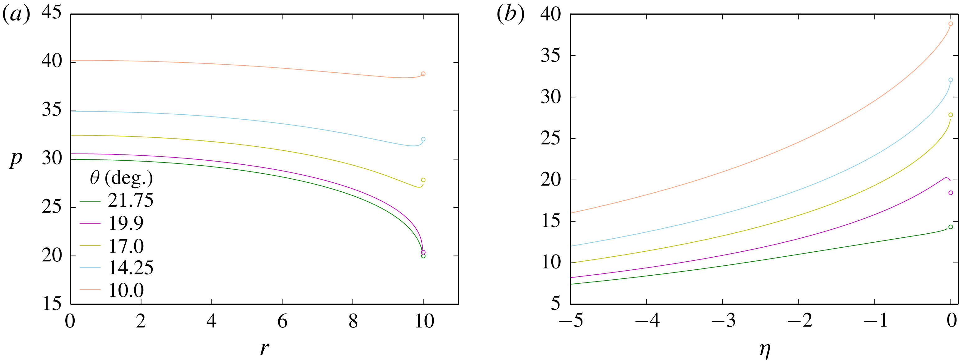
Figure 11. Pressure variation along (a) the shock front and (b) the deflected wall for various
 $\unicode[STIX]{x1D703}$
for
$\unicode[STIX]{x1D703}$
for
 $T=20.$
The circles show the polar analysis predicted shock and wall pressure at the explosive edge for each angle.
$T=20.$
The circles show the polar analysis predicted shock and wall pressure at the explosive edge for each angle.

Figure 12. Variation of axial detonation phase speed
 $D_{0}$
with wall deflection angle
$D_{0}$
with wall deflection angle
 $\unicode[STIX]{x1D703}$
for
$\unicode[STIX]{x1D703}$
for
 $T=100$
. The green line represents the flow streamline angle
$T=100$
. The green line represents the flow streamline angle
 $\unicode[STIX]{x1D703}_{s}$
, independent of
$\unicode[STIX]{x1D703}_{s}$
, independent of
 $D_{0}$
, at which the flow behind the detonation shock is sonic, as determined from the shock polar analysis. Also shown is a multi-material calculation (MM) for
$D_{0}$
, at which the flow behind the detonation shock is sonic, as determined from the shock polar analysis. Also shown is a multi-material calculation (MM) for
 $T=100$
confined by a weak (LIC) material.
$T=100$
confined by a weak (LIC) material.
6.2 Planar geometry for
$T=100$

Figure 12 shows the detonation phase speed variation with wall deflection angle for a wider planar geometry (
 $T=100$
). For this HE dimension, we see a much smaller overall change in
$T=100$
). For this HE dimension, we see a much smaller overall change in
 $D_{0}$
going from strong confinement wall deflection angles to weak confinement angles. As
$D_{0}$
going from strong confinement wall deflection angles to weak confinement angles. As
 $\unicode[STIX]{x1D703}$
is increased, the phase speed decreases monotonically, limiting to a constant for
$\unicode[STIX]{x1D703}$
is increased, the phase speed decreases monotonically, limiting to a constant for
 $\unicode[STIX]{x1D703}\geqslant 21$
as the effect of the confinement is saturated. As for
$\unicode[STIX]{x1D703}\geqslant 21$
as the effect of the confinement is saturated. As for
 $T=20,$
the phase speed is still decreasing through the angle
$T=20,$
the phase speed is still decreasing through the angle
 $\unicode[STIX]{x1D703}_{s}=19.471$
, where the polar analysis predicts that the flow behind the detonation shock at the wall should be sonic. The presumption is that
$\unicode[STIX]{x1D703}_{s}=19.471$
, where the polar analysis predicts that the flow behind the detonation shock at the wall should be sonic. The presumption is that
 $C^{+}$
characteristics from the wall are again playing a role in the structure of the DDZ. For the
$C^{+}$
characteristics from the wall are again playing a role in the structure of the DDZ. For the
 $T=100$
case, however, we do not observe any kink in the
$T=100$
case, however, we do not observe any kink in the
 $D_{0}$
variation seen for
$D_{0}$
variation seen for
 $T=20$
in the transition process to the weak confinement regime.
$T=20$
in the transition process to the weak confinement regime.
The corresponding variations in the DDZ structure for various
 $\unicode[STIX]{x1D703}$
are shown in figure 13. In each case, the detonation shock has positive curvature (divergent). However, the sonic locus variation is more complex. In each
$\unicode[STIX]{x1D703}$
are shown in figure 13. In each case, the detonation shock has positive curvature (divergent). However, the sonic locus variation is more complex. In each
 $\unicode[STIX]{x1D703}$
case, a significant section of the sonic locus extending away from the symmetry axis has positive curvature (divergent), although with the distance between the shock and sonic locus decreasing as one moves away from the symmetry axis. Near the wall, however, each sonic locus reaches a minimum in
$\unicode[STIX]{x1D703}$
case, a significant section of the sonic locus extending away from the symmetry axis has positive curvature (divergent), although with the distance between the shock and sonic locus decreasing as one moves away from the symmetry axis. Near the wall, however, each sonic locus reaches a minimum in
 $(r,z)$
space, and subsequently develops a region with negative curvature (convergent) extending to the wall, as shown in figure 13. Cases for
$(r,z)$
space, and subsequently develops a region with negative curvature (convergent) extending to the wall, as shown in figure 13. Cases for
 $\unicode[STIX]{x1D703}=10,$
 $14.5,$
 $17$
and
$17$
and
 $18.5$
correspond to strong confinement flow configurations where the shock and sonic locus are separated along the wall. Cases
$18.5$
correspond to strong confinement flow configurations where the shock and sonic locus are separated along the wall. Cases
 $\unicode[STIX]{x1D703}=21$
and
$\unicode[STIX]{x1D703}=21$
and
 $\unicode[STIX]{x1D703}=25.75$
have the sonic locus intersecting the detonation shock at the wall within the weakly confined flow regime (constant
$\unicode[STIX]{x1D703}=25.75$
have the sonic locus intersecting the detonation shock at the wall within the weakly confined flow regime (constant
 $D_{0}$
). Unlike the situation for
$D_{0}$
). Unlike the situation for
 $T=20,$
the sonic locus appears to transition smoothly from strong to weak confinement cases in the deflection angle range
$T=20,$
the sonic locus appears to transition smoothly from strong to weak confinement cases in the deflection angle range
 $\unicode[STIX]{x1D703}_{s}<\unicode[STIX]{x1D703}<21$
once sonic flow develops immediately behind the detonation shock at the wall
$\unicode[STIX]{x1D703}_{s}<\unicode[STIX]{x1D703}<21$
once sonic flow develops immediately behind the detonation shock at the wall
 $(\unicode[STIX]{x1D703}=\unicode[STIX]{x1D703}_{s})$
, with no observed large-scale changes in the sonic locus shape. The main changes in the DDZ sonic locus in the transition region are localized to the near-wall region, and consequently the variations in phase speed in the transition region (figure 12) from
$(\unicode[STIX]{x1D703}=\unicode[STIX]{x1D703}_{s})$
, with no observed large-scale changes in the sonic locus shape. The main changes in the DDZ sonic locus in the transition region are localized to the near-wall region, and consequently the variations in phase speed in the transition region (figure 12) from
 $\unicode[STIX]{x1D703}=\unicode[STIX]{x1D703}_{s}$
to
$\unicode[STIX]{x1D703}=\unicode[STIX]{x1D703}_{s}$
to
 $\unicode[STIX]{x1D703}=21$
are not as significant as those for
$\unicode[STIX]{x1D703}=21$
are not as significant as those for
 $T=20$
. A multi-material (MM) calculation is shown in figures 12 and 13 for comparison with the wall deflection simulations, having LIC material outside the HE. As seen for
$T=20$
. A multi-material (MM) calculation is shown in figures 12 and 13 for comparison with the wall deflection simulations, having LIC material outside the HE. As seen for
 $T=20,$
the agreement in the phase speed and DDZ structure is excellent when the angles in the wall deflection simulations are in the weak confinement regime.
$T=20,$
the agreement in the phase speed and DDZ structure is excellent when the angles in the wall deflection simulations are in the weak confinement regime.

Figure 13. (a) Evolution of the DDZ with
 $\unicode[STIX]{x1D703},$
enclosed by the detonation shock (solid lines) and sonic locus (dashed lines), for
$\unicode[STIX]{x1D703},$
enclosed by the detonation shock (solid lines) and sonic locus (dashed lines), for
 $T=100$
and a range of
$T=100$
and a range of
 $\unicode[STIX]{x1D703}$
from
$\unicode[STIX]{x1D703}$
from
 $\unicode[STIX]{x1D703}=10$
to
$\unicode[STIX]{x1D703}=10$
to
 $\unicode[STIX]{x1D703}=25.75$
. Also shown is a multi-material calculation (MM) for
$\unicode[STIX]{x1D703}=25.75$
. Also shown is a multi-material calculation (MM) for
 $T=100$
for weak (LIC) confinement. The DDZ structure for each
$T=100$
for weak (LIC) confinement. The DDZ structure for each
 $\unicode[STIX]{x1D703}$
has been offset such that the shock locus on
$\unicode[STIX]{x1D703}$
has been offset such that the shock locus on
 $r=0$
is set to
$r=0$
is set to
 $z=0.$
(b) A magnification of the DDZ structure near the deflected wall boundary.
$z=0.$
(b) A magnification of the DDZ structure near the deflected wall boundary.

Figure 14. The
 $C^{+}$
and
$C^{+}$
and
 $C^{-}$
characteristic paths in the supersonic flow region beyond the DDZ for
$C^{-}$
characteristic paths in the supersonic flow region beyond the DDZ for
 $T=100$
and (a)
$T=100$
and (a)
 $\unicode[STIX]{x1D703}=19.8,$
(b)
$\unicode[STIX]{x1D703}=19.8,$
(b)
 $\unicode[STIX]{x1D703}=21$
and (c)
$\unicode[STIX]{x1D703}=21$
and (c)
 $\unicode[STIX]{x1D703}=25.75.$
A selection of streamlines beyond the DDZ are also shown. The circles mark the end point of each characteristic path. The limiting
$\unicode[STIX]{x1D703}=25.75.$
A selection of streamlines beyond the DDZ are also shown. The circles mark the end point of each characteristic path. The limiting
 $C^{+}$
characteristic is shown as the blue dashed line, while the limiting
$C^{+}$
characteristic is shown as the blue dashed line, while the limiting
 $C^{-}$
characteristic is shown as the red dashed line
$C^{-}$
characteristic is shown as the red dashed line
We now examine the characteristic path structure for various
 $\unicode[STIX]{x1D703}$
behind the sonic locus to calculate the paths of characteristics from within the supersonic flow regions that impinge on the sonic locus. The case for
$\unicode[STIX]{x1D703}$
behind the sonic locus to calculate the paths of characteristics from within the supersonic flow regions that impinge on the sonic locus. The case for
 $\unicode[STIX]{x1D703}=19.8~({>}\unicode[STIX]{x1D703}_{s})$
is shown in figure 14(a). The sonic line intersects the detonation shock at the wall, and a weak local PM fan is present near the intersection point. The
$\unicode[STIX]{x1D703}=19.8~({>}\unicode[STIX]{x1D703}_{s})$
is shown in figure 14(a). The sonic line intersects the detonation shock at the wall, and a weak local PM fan is present near the intersection point. The
 $C^{+}$
and
$C^{+}$
and
 $C^{-}$
characteristic structure is interesting and complex. Near the wall, where the sonic locus is convergent in shape, the influence of
$C^{-}$
characteristic structure is interesting and complex. Near the wall, where the sonic locus is convergent in shape, the influence of
 $C^{+}$
characteristics emerging from the wall is similar to that seen for
$C^{+}$
characteristics emerging from the wall is similar to that seen for
 $T=20.$
A subset of
$T=20.$
A subset of
 $C^{+}$
characteristics leaving the wall downstream of the sonic point impinge on the sonic locus. However, the length of the wall over which
$C^{+}$
characteristics leaving the wall downstream of the sonic point impinge on the sonic locus. However, the length of the wall over which
 $C^{+}$
characteristics leave and impinge on the sonic surface is significantly shorter than that seen for
$C^{+}$
characteristics leave and impinge on the sonic surface is significantly shorter than that seen for
 $T=20$
even at
$T=20$
even at
 $\unicode[STIX]{x1D703}=19.8.$
A
$\unicode[STIX]{x1D703}=19.8.$
A
 $C^{+}$
limiting characteristic leaves the sidewall and is just tangent to the sonic locus near where the sonic locus changes convexity (figure 14
a). Thus the enclosed region of
$C^{+}$
limiting characteristic leaves the sidewall and is just tangent to the sonic locus near where the sonic locus changes convexity (figure 14
a). Thus the enclosed region of
 $C^{+}$
characteristics only intersect the sonic locus structure near the wall. For the positive curvature region of the sonic locus, we observe a new characteristic behaviour. There is now a fan of
$C^{+}$
characteristics only intersect the sonic locus structure near the wall. For the positive curvature region of the sonic locus, we observe a new characteristic behaviour. There is now a fan of
 $C^{-}$
characteristics that leave the sonic point at the symmetry axis, with the
$C^{-}$
characteristics that leave the sonic point at the symmetry axis, with the
 $C^{-}$
paths having
$C^{-}$
paths having
 $\text{d}z/\text{d}r=0$
at that point, and initially move downstream of the sonic locus before turning towards and then impinging on the sonic locus. Each point on the extensive divergent part of the sonic locus is impacted by
$\text{d}z/\text{d}r=0$
at that point, and initially move downstream of the sonic locus before turning towards and then impinging on the sonic locus. Each point on the extensive divergent part of the sonic locus is impacted by
 $C^{-}$
characteristics leaving the sonic point on the symmetry axis. Such
$C^{-}$
characteristics leaving the sonic point on the symmetry axis. Such
 $C^{-}$
trajectories are possible as the
$C^{-}$
trajectories are possible as the
 $C^{-}$
characteristic family have a surface where, as for
$C^{-}$
characteristic family have a surface where, as for
 $T=20$
,
$T=20$
,
 $\text{d}z/\text{d}r=0$
in the supersonic flow region. Again, these
$\text{d}z/\text{d}r=0$
in the supersonic flow region. Again, these
 $C^{-}$
characteristics carry information to the sonic surface through the supersonic flow region. There is a limiting
$C^{-}$
characteristics carry information to the sonic surface through the supersonic flow region. There is a limiting
 $C^{-}$
characteristic (shown) that extends significantly downstream of the sonic locus before glancing the sonic locus at a point slightly to the right of the sonic locus spatial minimum, and numerically close to the point at which the
$C^{-}$
characteristic (shown) that extends significantly downstream of the sonic locus before glancing the sonic locus at a point slightly to the right of the sonic locus spatial minimum, and numerically close to the point at which the
 $C^{+}$
limiting characteristic glances the sonic locus. The
$C^{+}$
limiting characteristic glances the sonic locus. The
 $C^{+}$
and
$C^{+}$
and
 $C^{-}$
limiting characteristics must be tangent to the sonic locus at the same point as a result of (5.2). The overall limiting characteristic, which marks the boundary between regions of supersonic flow that influence the sonic locus and those regions where characteristics flow information away from the sonic line, is formed by a combination of the
$C^{-}$
limiting characteristics must be tangent to the sonic locus at the same point as a result of (5.2). The overall limiting characteristic, which marks the boundary between regions of supersonic flow that influence the sonic locus and those regions where characteristics flow information away from the sonic line, is formed by a combination of the
 $C^{+}$
and
$C^{+}$
and
 $C^{-}$
limiting characteristics. In summary, the sonic locus for
$C^{-}$
limiting characteristics. In summary, the sonic locus for
 $T=100$
and
$T=100$
and
 $\unicode[STIX]{x1D703}=19.8$
is influenced by information propagated from the wall and symmetry axis. Despite the presence of local sonic flow immediately behind the detonation shock at the wall, information carried through the supersonic flow region from both the confinement boundary and symmetry axis affects the DDZ structure.
$\unicode[STIX]{x1D703}=19.8$
is influenced by information propagated from the wall and symmetry axis. Despite the presence of local sonic flow immediately behind the detonation shock at the wall, information carried through the supersonic flow region from both the confinement boundary and symmetry axis affects the DDZ structure.
For
 $\unicode[STIX]{x1D703}=21$
and
$\unicode[STIX]{x1D703}=21$
and
 $\unicode[STIX]{x1D703}=25.75$
(figure 14
b,c), the detonation phase speed is constant and the DDZ structure is fixed. An expansion fan structure is present with its origin at the intersection of the detonation shock and sonic locus, with
$\unicode[STIX]{x1D703}=25.75$
(figure 14
b,c), the detonation phase speed is constant and the DDZ structure is fixed. An expansion fan structure is present with its origin at the intersection of the detonation shock and sonic locus, with
 $C^{+}$
characteristics from the fan impinging on the sonic locus as for
$C^{+}$
characteristics from the fan impinging on the sonic locus as for
 $T=20.$
There are no
$T=20.$
There are no
 $C^{+}$
characteristics travelling directly from the wall that impinge on the sonic locus. The similarity of the DDZ structure between
$C^{+}$
characteristics travelling directly from the wall that impinge on the sonic locus. The similarity of the DDZ structure between
 $\unicode[STIX]{x1D703}=21$
and
$\unicode[STIX]{x1D703}=21$
and
 $\unicode[STIX]{x1D703}=25.75$
again indicates that the information carried by the
$\unicode[STIX]{x1D703}=25.75$
again indicates that the information carried by the
 $C^{+}$
characteristics that impinge on the sonic locus is the same, and only the section of the fan characteristics downstream of the
$C^{+}$
characteristics that impinge on the sonic locus is the same, and only the section of the fan characteristics downstream of the
 $C^{+}$
limiting characteristics are changing to meet the condition of the different wall deflection angles. Since the
$C^{+}$
limiting characteristics are changing to meet the condition of the different wall deflection angles. Since the
 $C^{-}$
limiting characteristic does not extend to the wall along the sonic surface, the DDZ structure is now fixed and the phase speed is the same for
$C^{-}$
limiting characteristic does not extend to the wall along the sonic surface, the DDZ structure is now fixed and the phase speed is the same for
 $\unicode[STIX]{x1D703}=21$
and
$\unicode[STIX]{x1D703}=21$
and
 $\unicode[STIX]{x1D703}=25.75.$
We again note that a similar situation of a combination of characteristics from different families combining to construct the overall limiting characteristic occurs in supersonic flow over a blunt body for moderate Mach numbers (Hayes & Probstein Reference Hayes and Probstein1966).
$\unicode[STIX]{x1D703}=25.75.$
We again note that a similar situation of a combination of characteristics from different families combining to construct the overall limiting characteristic occurs in supersonic flow over a blunt body for moderate Mach numbers (Hayes & Probstein Reference Hayes and Probstein1966).

Figure 15. As for figure 11, but with
 $T=100.$
A comparison of the shock pressure at the wall and the pressure on the wall between the shock polar theory and deflected wall simulations is shown in figure 15. The shock polar results are again based on the phase speed from the simulations at a given angle
 $\unicode[STIX]{x1D703}.$
The overall results are similar to those found for
$\unicode[STIX]{x1D703}.$
The overall results are similar to those found for
 $T=20.$
For the strongly confined cases
$T=20.$
For the strongly confined cases
 $\unicode[STIX]{x1D703}=10,$
 $14.5$
and
$14.5$
and
 $17,$
the simulation result and polar analysis are consistent. For
$17,$
the simulation result and polar analysis are consistent. For
 $\unicode[STIX]{x1D703}=19.6$
and
$\unicode[STIX]{x1D703}=19.6$
and
 $25.75,$
the flow is sonic immediately behind the detonation shock, and the shock pressure at the wall and wall pressure are again consistent with the local polar analysis involving the presence of a PM fan. The pressure variation along the shocks for
$25.75,$
the flow is sonic immediately behind the detonation shock, and the shock pressure at the wall and wall pressure are again consistent with the local polar analysis involving the presence of a PM fan. The pressure variation along the shocks for
 $\unicode[STIX]{x1D703}=19.6$
and
$\unicode[STIX]{x1D703}=19.6$
and
 $25.75$
are closer than for equivalent comparisons for
$25.75$
are closer than for equivalent comparisons for
 $T=20,$
even though the sonic locus structure and consequently the DDZ structure near the confinement boundary are different (figure 13). Again,
$T=20,$
even though the sonic locus structure and consequently the DDZ structure near the confinement boundary are different (figure 13). Again,
 $C^{+}$
characteristics impinging on the sonic locus from the confinement boundary for
$C^{+}$
characteristics impinging on the sonic locus from the confinement boundary for
 $\unicode[STIX]{x1D703}=19.6$
are responsible for modifying the DDZ structure from its limiting weak confinement structure, although for
$\unicode[STIX]{x1D703}=19.6$
are responsible for modifying the DDZ structure from its limiting weak confinement structure, although for
 $T=100$
the influence of the
$T=100$
the influence of the
 $C^{+}$
characteristics from the confinement boundary are localized to the near-wall region of the DDZ.
$C^{+}$
characteristics from the confinement boundary are localized to the near-wall region of the DDZ.
7 Axisymmetric cylindrical geometry for
$R=20$


Figure 16. Variation of axial detonation phase speed
 $D_{0}$
with wall deflection angle
$D_{0}$
with wall deflection angle
 $\unicode[STIX]{x1D703}$
for
$\unicode[STIX]{x1D703}$
for
 $R=20$
. The green line represents the fixed flow streamline angle
$R=20$
. The green line represents the fixed flow streamline angle
 $\unicode[STIX]{x1D703}_{s}$
, independent of
$\unicode[STIX]{x1D703}_{s}$
, independent of
 $D_{0}$
, at which the flow behind the detonation shock is sonic, as determined from the shock polar analysis. Also shown is a multi-material calculation (MM) for
$D_{0}$
, at which the flow behind the detonation shock is sonic, as determined from the shock polar analysis. Also shown is a multi-material calculation (MM) for
 $R=20$
confined by a weak (LIC) material.
$R=20$
confined by a weak (LIC) material.

Figure 17. (a) Evolution of the DDZ with
 $\unicode[STIX]{x1D703},$
enclosed by the detonation shock (solid lines) and sonic locus (dashed lines), for
$\unicode[STIX]{x1D703},$
enclosed by the detonation shock (solid lines) and sonic locus (dashed lines), for
 $R=20$
and a range of
$R=20$
and a range of
 $\unicode[STIX]{x1D703}$
from
$\unicode[STIX]{x1D703}$
from
 $\unicode[STIX]{x1D703}=14.5$
to
$\unicode[STIX]{x1D703}=14.5$
to
 $\unicode[STIX]{x1D703}=22.5$
. Also shown is a multi-material calculation (MM) for
$\unicode[STIX]{x1D703}=22.5$
. Also shown is a multi-material calculation (MM) for
 $R=20$
for weak (LIC) confinement. The DDZ structure for each
$R=20$
for weak (LIC) confinement. The DDZ structure for each
 $\unicode[STIX]{x1D703}$
has been offset such that the shock locus on
$\unicode[STIX]{x1D703}$
has been offset such that the shock locus on
 $r=0$
is set to
$r=0$
is set to
 $z=0.$
(b) A magnification of the DDZ structure near the deflected wall boundary.
$z=0.$
(b) A magnification of the DDZ structure near the deflected wall boundary.
Figure 16 shows the detonation phase speed variation with wall deflection angle for an axisymmetric cylindrical geometry with radius
 $R=20.$
The cylindrical geometry imparts a second component of curvature on the detonation shock front. If the front were shaped as a spherical cap, the total shock curvature for the planar geometry with
$R=20.$
The cylindrical geometry imparts a second component of curvature on the detonation shock front. If the front were shaped as a spherical cap, the total shock curvature for the planar geometry with
 $T=20$
(§ 6.1) and the cylindrical geometry with
$T=20$
(§ 6.1) and the cylindrical geometry with
 $R=20$
would be the same (Jackson & Short Reference Jackson and Short2015). Corresponding DDZ structures are presented in figure 17. The phase speed variation and DDZ structures have similar properties to those observed for the larger planar geometry case with
$R=20$
would be the same (Jackson & Short Reference Jackson and Short2015). Corresponding DDZ structures are presented in figure 17. The phase speed variation and DDZ structures have similar properties to those observed for the larger planar geometry case with
 $T=100$
(§ 6.2). The phase speed decreases monotonically with increasing
$T=100$
(§ 6.2). The phase speed decreases monotonically with increasing
 $\unicode[STIX]{x1D703}$
before limiting to a constant for
$\unicode[STIX]{x1D703}$
before limiting to a constant for
 $\unicode[STIX]{x1D703}\geqslant 21.$
The DDZ structure again senses the influence of the confinement boundary beyond the sonic flow angle
$\unicode[STIX]{x1D703}\geqslant 21.$
The DDZ structure again senses the influence of the confinement boundary beyond the sonic flow angle
 $\unicode[STIX]{x1D703}_{s}=19.471$
determined by the polar analysis (note that for a given
$\unicode[STIX]{x1D703}_{s}=19.471$
determined by the polar analysis (note that for a given
 $D_{0},$
the polar analysis does not make any distinction between the planar and cylindrical geometries). The sonic locus of the DDZ has positive curvature near the symmetry axis and negative curvature near the wall. In comparison to the
$D_{0},$
the polar analysis does not make any distinction between the planar and cylindrical geometries). The sonic locus of the DDZ has positive curvature near the symmetry axis and negative curvature near the wall. In comparison to the
 $T=100$
DDZ structure, the sonic locus is more shallow near the symmetry axis, while the negative curvature region near the wall is more pronounced. The DDZ structure can be thought of as intermediate to the
$T=100$
DDZ structure, the sonic locus is more shallow near the symmetry axis, while the negative curvature region near the wall is more pronounced. The DDZ structure can be thought of as intermediate to the
 $T=20$
and
$T=20$
and
 $T=100$
cases.
$T=100$
cases.

Figure 18. The
 $C^{+}$
and
$C^{+}$
and
 $C^{-}$
characteristic paths in the supersonic flow region beyond the DDZ for
$C^{-}$
characteristic paths in the supersonic flow region beyond the DDZ for
 $R=20$
and (a)
$R=20$
and (a)
 $\unicode[STIX]{x1D703}=14.5,$
(b)
$\unicode[STIX]{x1D703}=14.5,$
(b)
 $\unicode[STIX]{x1D703}=19.8,$
(c)
$\unicode[STIX]{x1D703}=19.8,$
(c)
 $\unicode[STIX]{x1D703}=21$
and (d)
$\unicode[STIX]{x1D703}=21$
and (d)
 $\unicode[STIX]{x1D703}=22.5$
. A selection of streamlines beyond the DDZ are also shown. The circles mark the end point of each characteristic path. The limiting
$\unicode[STIX]{x1D703}=22.5$
. A selection of streamlines beyond the DDZ are also shown. The circles mark the end point of each characteristic path. The limiting
 $C^{+}$
characteristic is shown as the dashed blue line, while the limiting
$C^{+}$
characteristic is shown as the dashed blue line, while the limiting
 $C^{-}$
characteristic is shown as the dashed red line
$C^{-}$
characteristic is shown as the dashed red line
The
 $C^{+}$
and
$C^{+}$
and
 $C^{-}$
characteristic paths for
$C^{-}$
characteristic paths for
 $\unicode[STIX]{x1D703}=14.5,$
 $19.8,$
 $21$
and
$21$
and
 $22.5$
are shown in figure 18. For the strongly confined case
$22.5$
are shown in figure 18. For the strongly confined case
 $\unicode[STIX]{x1D703}=14.5,$
 $C^{+}$
characteristics leaving the wall downstream of the sonic point on the wall impinge on the negative curvature region of the sonic locus. A
$C^{+}$
characteristics leaving the wall downstream of the sonic point on the wall impinge on the negative curvature region of the sonic locus. A
 $C^{+}$
limiting characteristic marking the boundary of influence of the wall on the sonic locus can be calculated and is tangent to the sonic locus at a point just to the right of the minimum in the sonic locus. A subset of
$C^{+}$
limiting characteristic marking the boundary of influence of the wall on the sonic locus can be calculated and is tangent to the sonic locus at a point just to the right of the minimum in the sonic locus. A subset of
 $C^{-}$
characteristics fan from the sonic point on the symmetry axis and impinge on the sonic locus over a substantial length of the locus, as for the planar
$C^{-}$
characteristics fan from the sonic point on the symmetry axis and impinge on the sonic locus over a substantial length of the locus, as for the planar
 $T=100$
case. The
$T=100$
case. The
 $C^{-}$
limiting characteristic is tangent to the sonic locus slightly to the right of its minimum, again numerically close to the tangent point of the
$C^{-}$
limiting characteristic is tangent to the sonic locus slightly to the right of its minimum, again numerically close to the tangent point of the
 $C^{+}$
limiting characteristic. The transition region case for
$C^{+}$
limiting characteristic. The transition region case for
 $\unicode[STIX]{x1D703}=19.8~({>}\unicode[STIX]{x1D703}_{s})$
has the sonic line intersecting the detonation shock at the wall, and a weak local PM fan present near the intersection point (figure 18
b). The
$\unicode[STIX]{x1D703}=19.8~({>}\unicode[STIX]{x1D703}_{s})$
has the sonic line intersecting the detonation shock at the wall, and a weak local PM fan present near the intersection point (figure 18
b). The
 $C^{+}$
and
$C^{+}$
and
 $C^{-}$
characteristic structures are similar to that seen for the transition case for
$C^{-}$
characteristic structures are similar to that seen for the transition case for
 $T=100$
(figure 14
a). However, since the negative curvature region of the sonic locus near the wall is more pronounced than for the planar geometry with
$T=100$
(figure 14
a). However, since the negative curvature region of the sonic locus near the wall is more pronounced than for the planar geometry with
 $T=100,$
the region of the wall from which
$T=100,$
the region of the wall from which
 $C^{+}$
characteristics impact on the sonic locus is larger than for the
$C^{+}$
characteristics impact on the sonic locus is larger than for the
 $T=100$
case. The cases shown for
$T=100$
case. The cases shown for
 $\unicode[STIX]{x1D703}=21$
and
$\unicode[STIX]{x1D703}=21$
and
 $\unicode[STIX]{x1D703}=22.5$
(figure 18
c,d) are where the phase speed is constant and the DDZ structure fixed. Again, as for
$\unicode[STIX]{x1D703}=22.5$
(figure 18
c,d) are where the phase speed is constant and the DDZ structure fixed. Again, as for
 $T=100,$
an expansion fan has formed with its origin at the intersection point of the detonation shock and sonic locus on the wall. The
$T=100,$
an expansion fan has formed with its origin at the intersection point of the detonation shock and sonic locus on the wall. The
 $C^{+}$
characteristics from within the fan intersect the sonic line, and include a limiting characteristic defining the region of influence of the
$C^{+}$
characteristics from within the fan intersect the sonic line, and include a limiting characteristic defining the region of influence of the
 $C^{+}$
characteristics, while
$C^{+}$
characteristics, while
 $C^{+}$
characteristics leaving the wall do not reach the sonic locus. The
$C^{+}$
characteristics leaving the wall do not reach the sonic locus. The
 $C^{-}$
limiting characteristics do not reach the wall along the sonic locus, and with the
$C^{-}$
limiting characteristics do not reach the wall along the sonic locus, and with the
 $D_{0}$
and the DDZ structure the same for
$D_{0}$
and the DDZ structure the same for
 $\unicode[STIX]{x1D703}\geqslant 21,$
the
$\unicode[STIX]{x1D703}\geqslant 21,$
the
 $C^{+}$
and
$C^{+}$
and
 $C^{-}$
characteristics reaching the sonic locus must carry the same information and thus the effect of the confinement has saturated. Again, though, some information about the confinement through the fan structure is imparted on the sonic locus and affects the DDZ structure. A multi-material (MM) calculation is shown in figures 16 and 17 for comparison with the wall deflection simulations in the cylindrical geometry, having LIC material outside the HE. Once again, the agreement in the phase speed and DDZ structure is excellent for the weak confinement regime. Figure 19 shows a comparison between the shock pressure behind the shock at the wall as well as the wall pressure from the shock polar theory with the simulation shock pressure at the wall and the wall pressure. A very similar picture emerges to that for
$C^{-}$
characteristics reaching the sonic locus must carry the same information and thus the effect of the confinement has saturated. Again, though, some information about the confinement through the fan structure is imparted on the sonic locus and affects the DDZ structure. A multi-material (MM) calculation is shown in figures 16 and 17 for comparison with the wall deflection simulations in the cylindrical geometry, having LIC material outside the HE. Once again, the agreement in the phase speed and DDZ structure is excellent for the weak confinement regime. Figure 19 shows a comparison between the shock pressure behind the shock at the wall as well as the wall pressure from the shock polar theory with the simulation shock pressure at the wall and the wall pressure. A very similar picture emerges to that for
 $T=100$
despite the change in geometry.
$T=100$
despite the change in geometry.

Figure 19. As for figure 11, but with
 $R=20.$
In conclusion, the construction of the limiting characteristics for the three cases above defining the range of influence of the characteristics from the confinement boundary (strong confinement) or the expansion fan (weak confinement) and the symmetry axis (for large planar and cylindrical geometries) that propagate information through the supersonic flow region behind the sonic locus and ultimately impinge on the sonic locus, thus affecting the DDZ structure, shows that the dynamics of the detonation confinement problem are significantly more complicated than those described in § 1.
8 Summary
For steady two-dimensional detonation propagation in a condensed-phase explosive, we have examined the characteristic paths of information propagation through the supersonic flow regime downstream of the sonic locus of the detonation driving zone (DDZ), in order to examine the circumstances under which a subset of characteristics may impinge, and deposit information, on the sonic locus and thus influence the structure of the subsonic elliptical flow region defining the DDZ. A numerical strategy was employed whereby a solid wall boundary at the edge of the explosive was deflected through a pre-specified angle on detonation shock arrival, so that the streamline turning angle of the wall at the edge of the explosive was unambiguously defined. By varying the wall deflection angle from small through large values, we were able to systematically capture the evolution of the DDZ structure, and the supersonic flow regions that influence its structure, for strongly confined to weakly confined detonations. Two-dimensional planar geometries were examined for thin and thick explosive dimensions, along with an axisymmetric cylindrical geometry.
We found that for strongly confined detonations a subset of
 $C^{+}$
characteristic paths, carrying information from the confinement boundary through the supersonic flow region behind the sonic locus, impinge on the detonation sonic locus, impacting the structure of the DDZ. For the current studies, we have not found an example of a bounding characteristic for strongly confined detonations, as discussed in § 1, in which the confinement boundary downstream of the sonic locus has no influence on the DDZ. For weakly confined detonations, we found that there is always a subset of
$C^{+}$
characteristic paths, carrying information from the confinement boundary through the supersonic flow region behind the sonic locus, impinge on the detonation sonic locus, impacting the structure of the DDZ. For the current studies, we have not found an example of a bounding characteristic for strongly confined detonations, as discussed in § 1, in which the confinement boundary downstream of the sonic locus has no influence on the DDZ. For weakly confined detonations, we found that there is always a subset of
 $C^{+}$
characteristics, originating from the expansion fan at the intersection of detonation shock and sonic locus, that flow through the supersonic region and impinge on the sonic locus. Depending on the configuration,
$C^{+}$
characteristics, originating from the expansion fan at the intersection of detonation shock and sonic locus, that flow through the supersonic region and impinge on the sonic locus. Depending on the configuration,
 $C^{-}$
characteristic paths originating from the sonic flow point on the symmetry axis can also run through the supersonic flow region and impinge on the sonic surface. In each confinement case, a limiting characteristic boundary can be defined separating regions where information propagated along characteristics in the supersonic flow region reaches the sonic locus from those regions where information is carried away from the sonic locus. There are similarities in the current study to supersonic and hypersonic flow over a symmetric blunt body discussed by Hayes & Probstein (Reference Hayes and Probstein1966), where the sonic surfaces connecting the bow shock to the body, and the subsonic flow contained within the sonic surfaces, are influenced by the impingement of supersonic flow characteristics from behind the sonic surface.
$C^{-}$
characteristic paths originating from the sonic flow point on the symmetry axis can also run through the supersonic flow region and impinge on the sonic surface. In each confinement case, a limiting characteristic boundary can be defined separating regions where information propagated along characteristics in the supersonic flow region reaches the sonic locus from those regions where information is carried away from the sonic locus. There are similarities in the current study to supersonic and hypersonic flow over a symmetric blunt body discussed by Hayes & Probstein (Reference Hayes and Probstein1966), where the sonic surfaces connecting the bow shock to the body, and the subsonic flow contained within the sonic surfaces, are influenced by the impingement of supersonic flow characteristics from behind the sonic surface.
For the planar explosive geometry with a thickness
 $T=20$
, the DDZ sonic locus has a monotonically convergent shape, except in the transition regime between strong and weak confinement limits. We found that the limiting characteristic is defined only by the
$T=20$
, the DDZ sonic locus has a monotonically convergent shape, except in the transition regime between strong and weak confinement limits. We found that the limiting characteristic is defined only by the
 $C^{+}$
characteristics propagating from either the confinement boundary (strong confinement) or expansion fan (weak confinement). The point on the deflected wall where the limiting characteristic originates for confined flows moves towards the detonation shock as the weak confinement limit deflection angles are approached. The DDZ structure in the transition regime between strong and weak confinement cases is interesting for the thin planar geometry, where
$C^{+}$
characteristics propagating from either the confinement boundary (strong confinement) or expansion fan (weak confinement). The point on the deflected wall where the limiting characteristic originates for confined flows moves towards the detonation shock as the weak confinement limit deflection angles are approached. The DDZ structure in the transition regime between strong and weak confinement cases is interesting for the thin planar geometry, where
 $C^{+}$
characteristic information from the confinement boundary causes the development of an S-shaped sonic locus. In the weak confinement regime, the detonation phase speed remains constant and the DDZ structure spatially fixed for increasing wall deflection angles. We showed that the paths of
$C^{+}$
characteristic information from the confinement boundary causes the development of an S-shaped sonic locus. In the weak confinement regime, the detonation phase speed remains constant and the DDZ structure spatially fixed for increasing wall deflection angles. We showed that the paths of
 $C^{+}$
characteristics within the expansion fan that impinge on the sonic locus above the
$C^{+}$
characteristics within the expansion fan that impinge on the sonic locus above the
 $C^{+}$
limiting characteristic, and the flow information they carry, are the same for increasing wall deflection angles, that is, the effect of confinement on the DDZ structure has been saturated.
$C^{+}$
limiting characteristic, and the flow information they carry, are the same for increasing wall deflection angles, that is, the effect of confinement on the DDZ structure has been saturated.
For both the planar explosive geometry with a thickness
 $T=100$
and the axisymmetric cylindrical geometry with
$T=100$
and the axisymmetric cylindrical geometry with
 $R=20,$
the sonic line shape is divergent near the symmetry axis, but convergent towards the explosive boundary. The overall limiting characteristic is then constructed from the two families of
$R=20,$
the sonic line shape is divergent near the symmetry axis, but convergent towards the explosive boundary. The overall limiting characteristic is then constructed from the two families of
 $C^{+}$
and
$C^{+}$
and
 $C^{-}$
characteristics. The first comes from the
$C^{-}$
characteristics. The first comes from the
 $C^{+}$
limiting characteristic from either the confinement boundary or expansion fan at the explosive edge. The
$C^{+}$
limiting characteristic from either the confinement boundary or expansion fan at the explosive edge. The
 $C^{-}$
characteristics from the sonic point on the symmetry axis also impinge on the sonic surface and modify the sonic locus and DDZ flow. The second then comes from the
$C^{-}$
characteristics from the sonic point on the symmetry axis also impinge on the sonic surface and modify the sonic locus and DDZ flow. The second then comes from the
 $C^{-}$
limiting characteristic defining the extent of influence of
$C^{-}$
limiting characteristic defining the extent of influence of
 $C^{-}$
characteristics from the axis on the sonic locus. Again, a similar situation can arise in supersonic blunt-body flows for moderate inflow Mach numbers (Hayes & Probstein Reference Hayes and Probstein1966), where the limiting characteristic is determined from both families of characteristics in the supersonic flow region.
$C^{-}$
characteristics from the axis on the sonic locus. Again, a similar situation can arise in supersonic blunt-body flows for moderate inflow Mach numbers (Hayes & Probstein Reference Hayes and Probstein1966), where the limiting characteristic is determined from both families of characteristics in the supersonic flow region.
For the planar and cylindrical geometries, we have compared the DDZ structure with a multi-material calculation in which the confinement is a low-impedance plastic material corresponding to the weak confinement regime. Excellent agreement between the phase speed and DDZ structures from the deflected wall and multi-material calculations are found, a result which can be explained by the saturation effect of information carried by characteristics impinging on the sonic locus in the weak confinement limit. In all cases, the ability for
 $C^{+}$
and
$C^{+}$
and
 $C^{-}$
characteristics in the supersonic flow region to turn into the sonic locus is due to the presence of continued reaction behind the sonic surface as well as due to geometry effects.
$C^{-}$
characteristics in the supersonic flow region to turn into the sonic locus is due to the presence of continued reaction behind the sonic surface as well as due to geometry effects.
Oblique-shock polar analysis has been used to gauge the effect on the DDZ of characteristics from the supersonic flow region impinging on the sonic locus. The polar theory is based on the specified wall deflection angle as well as the detonation phase speed obtained from the simulations. We found that, while a shock polar analysis can adequately describe the local flow structure near the edge of the explosive for a specified detonation phase speed, it provides limited information on the non-local, global steady DDZ detonation structure that arises due to the influence of characteristics impinging on the sonic surface. These results also indicate that due care must be exercised when using a shock polar-based theory to set the confinement angles at the explosive–confiner interface required for surface wave approaches to calculating detonation motion such as detonation shock dynamics (Bdzil & Stewart Reference Bdzil and Stewart2007).
While we have shown that characteristics from the supersonic flow regions impinge on the sonic surface under all confinement conditions studied, it is difficult to gauge the absolute magnitude of their influence due to the nature of the mixed steady subsonic–sonic–supersonic flow structure. In follow-up studies, we will present studies in which, for the strong confinement cases, the wall boundary is deflected through a second angle immediately downstream of where the sonic locus on the wall is located. Such an effect will modify the information flow from the wall boundary downstream of the sonic locus. Changes in the phase speed and DDZ structure will allow us to study the influence of the flow from within the limiting characteristics. We also propose a comparison of the characteristic paths calculated here with multi-material calculations for specific confiner materials. Although this is significantly more challenging due to numerical issues with capturing the material interface, our preliminary studies show a very similar behaviour to that seen above for both strongly and weakly confining materials, i.e. a subset of characteristics impinge on the sonic locus for all confinement scenarios. In short, based on the work conducted here, the detonation confinement problem is significantly more complicated than previously understood.


