


NOMENCLATURE
- c
chord
- C u0
steady component of jet momentum coefficient
- Cum
unsteady component of jet momentum coefficient
- d
length of jet orifice along spanwise direction
- F +
jet frequency
- Fv
viscous fluxes
- Fc
convective fluxes
- h
length of jet orifice along chordwise direction
- M tip
mach number at the blade tip
- Ma
mach number
- njet
direction vector of synthetic jet
- R
radius of rotor
- S
boundary of grid cell
- t
real time
- t*
non-dimensional time
- U tip
velocity of blade tip
- U 0
amplitude of the steady components of velocity
- Um
amplitude of the unsteady components of velocity
- W
conservation variables
- τ
pseudo-time
- Ω
volume of grid cell
- ξ
chordwise direction
- ωjet
excitation frequency of jet
- ωrotor
angular velocity of rotor
- η
cross-stream direction
- ζ
spanwise direction
- μ
advance ratio
- ΔCl
lift coefficient increment
- θ
synthetic jet angle
- ψ
azimuthal angle
1.0 INTRODUCTION
The aerodynamic characteristic of the rotor has an important impact on the flight performance of the helicopter. To avoid the large rolling moment and maintain the high lift of the blade, the retreating blade is always operated under a large Angle-of-Attack (AoA), while the AoA of the advancing side is much lower(Reference Leishman1). This periodic variation of AoA makes the rotor undergo dynamic stall in the retreating side, and this phenomenon may induce the flow separation on the surface of the rotor blade in forward flight(Reference Yu, Lee, McAlister, Tung and Wang2), resulting in the decrease of the lift and the increase of the vibration level. Therefore, the investigation on preventing the flow separation and improving the aerodynamic characteristic of the rotor has become one of the key and difficult points in the field of helicopter technology. In recent years, it has been observed that the active flow control was one of the most promising methods for improving the aerodynamic characteristic of the aerofoil, and further expanding the operating envelope of the rotorcraft(Reference Liipfert, Pottler and Ulmer3-Reference Xia and Zhong5), and it is indicated to be one of the main design strategies of the advanced rotor in the future(Reference Nagib, Greenblatt and Kiedaisch6,Reference Woo, Crittenden and Glezer7) .
As a novel active flow-control method, the synthetic jet is an efficient technology to control the flow separation and the stall of the aerofoil(Reference Smith and Glezer8-Reference Hassan11). In order to explore the control mechanism of the synthetic jet on the flow separation, Seifert(Reference Seifert, Darabi and Wygnanski12) conducted active control experiments on NACA0015 aerofoil, and the capability of the synthetic jet on delaying the stall of the aerofoil was verified. Several experimental results indicated that the synthetic jet localised near the location where the flow separation formed can significantly enhance stall characteristics of the aerofoil, including the increment of the maximum lift and the stall angle(Reference Gilarranz, Traub and Rediniotis13-Reference Monir, Tadjfar and Bakhtian15).
In the aspect of numerical simulations of the synthetic jet control, Kral(Reference Kral, Donovan and Cain16) introduced a tangential synthetic jet at the leading edge of NACA0015 aerofoil, and used a Reynolds-averaged Navier-Stokes (RANS) equations to investigate the effect of the synthetic jet on the flow over the aerofoil, and it was demonstrated that the RANS approach could be used to effectively simulate the active flow control by employing unsteady jets. Lorber(Reference Lorber, McCormick and Anderson17) conducted the investigations on delaying the retreating blade stall by the directed synthetic jet (DSJ) for aerofoil SC2110. Hassan(Reference Hassan, Straub and Charles18) numerically simulated the effects of surface bowing and suction on the aerodynamic characteristics of the five-bladed MD-900 rotor in a low-speed descent flight by solving the unsteady 3D full-potential equations. Based on Euler equations, Dindar(Reference Dindar, Jansen and Hassan19) numerically investigated the potential merits of using the transpiration flow control on the rotor in hovering flight. However, their work is difficult to simulate the rotor vortex flowfield and the detail of the jet flow due to the restriction of their methods.
In addition, there are still some questions which have not been overcome in the applications of synthetic jets(Reference Cain, Kral, Donovan and Smith20). The application of the synthetic jet on rotors is still theoretic because of numerous controlling parameters, such as the jet location, the jet momentum coefficient and the jet angle. Furthermore, the parametric analysis of the dual-jet control effect on the aerodynamic characteristic of rotors has not been carried out well.
In this paper, numerical simulations about the active flow control of the rotor by using the synthetic jet are conducted systematically. First, the solution of the rotor flowfield is obtained by solving the unsteady RANS equations with k-ω SST turbulence model, and a moving-embedded grid method is employed. Surface points of the blade with a synthetic jet orifice are constructed, and grids around the section of the blade are quickly generated by solving Poisson equations. Additionally, a dimensionless velocity boundary condition is established to simulate flow control effects of the synthetic jet on the blade surface. By comparing the calculated results and the test data about the synthetic jet on the aerofoil, the feasibility and efficiency of the present numerical method are evaluated. Furthermore, parametric analyses of the synthetic jet are carried out to investigate the control mechanism of the synthetic jet on the aerodynamic characteristic of the rotor in forward flight, and some conclusions are obtained.
2.0 METHODOLOGIES
2.1 Flowfield solution method
The CFD methods(21) based on unsteady RANS equations are employed to simulate the flowfield of the rotor.
 $$\begin{equation}
\frac{\partial }{{\partial \tau }}\int{{{{\bf W}}d\Omega }} + \frac{\partial }{{\partial t}}\int{{{{\bf W}}d\Omega }} + \oint {({{{\bf F}}_c} - {{{\bf F}}_\upsilon })dS} = 0
\end{equation}$$
$$\begin{equation}
\frac{\partial }{{\partial \tau }}\int{{{{\bf W}}d\Omega }} + \frac{\partial }{{\partial t}}\int{{{{\bf W}}d\Omega }} + \oint {({{{\bf F}}_c} - {{{\bf F}}_\upsilon })dS} = 0
\end{equation}$$
where W are conservation variables, Fv are the viscous fluxes, and Fc are convective fluxes including the motion of the dynamic grid system. τ and t are the pseudo time and the real time respectively. Ω is the volume of the grid cell, and S is the boundary of the grid cell.
The dual-time method is used to simulate the unsteady flowfield of the rotor, and the sub-iteration is fulfilled by the implicit LU-SGS method(Reference Sharov and Nakahashi22) which can be implemented easily on vector and parallel computers. To accurately predict the non-linear and unsteady vortical flowfield of the rotor, the third-order Roe scheme and the MUSCL approach(Reference Edwards, Franklin and Liou23) are employed for the discretisation of convective fluxes. Trying to simulate the flow separation over the surface of the rotor blade, the k-ω SST turbulence model(Reference Menter24) is employed to calculate the turbulence viscosity.
2.2 Grid generation method
The quality of grids around the rotor has a direct influence on the flowfield solution precision. There are three steps in the grid generation for active flow-control investigations on the rotor. First, the body-fitted and orthogonal C-type grids around rotor aerofoils are generated by solving Poisson equations. To capture the flow characteristics of the synthetic jet in detail, clustering grids over the orifice are generated. Second, C-O type grids around the rotor blade are generated automatically. At last, the moving-embedded grids are generated including two key points: (Reference Leishman1) identification for the boundary cell of the hole; (Reference Yu, Lee, McAlister, Tung and Wang2) searching of donor elements. The ‘top-map’ method and the ‘PSSDE’ method(Reference Wang, Zhao and Xu25) are adopted in the procedure of embedded grids. Body-fitted grids around rotors are shown in Fig. 1.
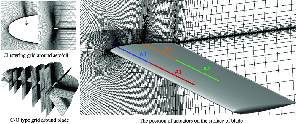
Figure 1. Body-fitted grids around rotor aerofoil and blade.
2.3 Boundary condition of synthetic jet
The flow perturbation from the synthetic jet actuator on the rotor is modeled by a suction/blowing type boundary condition(Reference Donovan, Kral and Cary26).
The non-dimensional velocity of the synthetic jet at the actuator surface is introduced by:
 $$\begin{equation}
{{\bf V}}(\xi ,\eta =0,\zeta ,t) = \sqrt {\frac{{Rc}}{{2hd}}} {U_{{\rm{tip}}}}\left[\sqrt {{C_{u0}}} + \sqrt {2{C_{um}}} {\rm{sin}}\left({\omega _{{\rm{rotor}}}}{F^ + }t\frac{c}{{{U_{{\rm{tip}}}}}}\right)\right]{{\bf n}}{}_{{\rm{jet}}},
\end{equation}$$
$$\begin{equation}
{{\bf V}}(\xi ,\eta =0,\zeta ,t) = \sqrt {\frac{{Rc}}{{2hd}}} {U_{{\rm{tip}}}}\left[\sqrt {{C_{u0}}} + \sqrt {2{C_{um}}} {\rm{sin}}\left({\omega _{{\rm{rotor}}}}{F^ + }t\frac{c}{{{U_{{\rm{tip}}}}}}\right)\right]{{\bf n}}{}_{{\rm{jet}}},
\end{equation}$$
where ξ denotes the chordwise direction, η denotes the cross-stream direction, ζ denotes the spanwise direction, F + denotes the jet frequency, C u0 is the steady component of jet momentum coefficient, Cum is the unsteady component of jet momentum coefficient, ωrotor is the angular velocity of rotor, njet is the direction vector of synthetic jet, h is the length of the jet orifice along the chordwise direction, d is the length of the jet orifice along the spanwise direction, R is the radius of the rotor, and U tip is the velocity of the blade tip, as shown in Fig. 2.
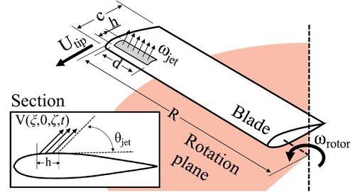
Figure 2. Jet boundary condition on the surface of the helicopter rotor.
The non-dimensional jet excitation frequency is determined by:
 $$\begin{equation}
{F^ + } = \frac{{\frac{{{\omega _{{\rm{jet}}}}}}{{2\pi }}}}{{\frac{{{\omega _{{\rm{rotor}}}}}}{{2\pi }}}} = \frac{\omega_{\rm{jet}}}{\raise3pt\hbox{$\omega_{\rm rotor}$}}
\end{equation}$$
$$\begin{equation}
{F^ + } = \frac{{\frac{{{\omega _{{\rm{jet}}}}}}{{2\pi }}}}{{\frac{{{\omega _{{\rm{rotor}}}}}}{{2\pi }}}} = \frac{\omega_{\rm{jet}}}{\raise3pt\hbox{$\omega_{\rm rotor}$}}
\end{equation}$$
The instantaneous velocity of the synthetic jet and the non-dimensional jet momentum coefficient are determined by:
 $$\begin{equation}
\begin{array}{*{20}{c}} {U(t) = {U_0} + {U_m}{\rm{sin}}({\omega _{{\rm{jet}}}}t),}&{{C_{u0}} = 2\displaystyle\frac{{hd}}{{Rc}}{{\left( {\displaystyle\frac{{U{}_0}}{{{U_{{\rm{tip}}}}}}} \right)}^2},}&{{C_{um}} = 2\displaystyle\frac{{hd}}{{Rc}}{{\left( {\displaystyle\frac{{{U_m}}}{{\sqrt 2 {U_{{\rm{tip}}}}}}} \right)}^2}} \end{array},
\end{equation}$$
$$\begin{equation}
\begin{array}{*{20}{c}} {U(t) = {U_0} + {U_m}{\rm{sin}}({\omega _{{\rm{jet}}}}t),}&{{C_{u0}} = 2\displaystyle\frac{{hd}}{{Rc}}{{\left( {\displaystyle\frac{{U{}_0}}{{{U_{{\rm{tip}}}}}}} \right)}^2},}&{{C_{um}} = 2\displaystyle\frac{{hd}}{{Rc}}{{\left( {\displaystyle\frac{{{U_m}}}{{\sqrt 2 {U_{{\rm{tip}}}}}}} \right)}^2}} \end{array},
\end{equation}$$
where U 0 and Um are the amplitude value of steady and unsteady components of the velocity, respectively.
The non-dimensional time and the definition of the angular velocity of the rotor are:
 $$\begin{equation}
\begin{array}{*{20}{c}} {{t^ * } = \displaystyle\frac{t}{{c/{U_{{\rm{tip}}}}}},}&{{\omega _{{\rm{rotor}}}} = \displaystyle\frac{{{U_{{\rm{tip}}}}}}{R}} \end{array}\vspace*{-3pt}
\end{equation}$$
$$\begin{equation}
\begin{array}{*{20}{c}} {{t^ * } = \displaystyle\frac{t}{{c/{U_{{\rm{tip}}}}}},}&{{\omega _{{\rm{rotor}}}} = \displaystyle\frac{{{U_{{\rm{tip}}}}}}{R}} \end{array}\vspace*{-3pt}
\end{equation}$$
The boundary condition of the synthetic jet on the rotor can be converted to:
 $$\begin{equation}
{{\bf V}}(\xi ,0,\zeta ,t) = \sqrt {\frac{{Rc}}{{2hd}}} {U_{{\rm{tip}}}}\left[\sqrt {{C_{u0}}} + \sqrt {2{C_{um}}} {\rm{sin}}\left( {\frac{c}{R}{F^ + }t} \right)\right]{{\bf n}}{}_{{\rm{jet}}}
\end{equation}$$
$$\begin{equation}
{{\bf V}}(\xi ,0,\zeta ,t) = \sqrt {\frac{{Rc}}{{2hd}}} {U_{{\rm{tip}}}}\left[\sqrt {{C_{u0}}} + \sqrt {2{C_{um}}} {\rm{sin}}\left( {\frac{c}{R}{F^ + }t} \right)\right]{{\bf n}}{}_{{\rm{jet}}}
\end{equation}$$
3.0 RESULTS AND ANALYSES
3.1 Jet control of rotor aerofoil
The baseline case for NACA0015 under a condition of Ma = 0.15 and Re = 1.85 × 10⁶ is calculated firstly. The grid has a resolution of 447 × 90. There are 185 points on the lower and upper surfaces of the aerofoil, respectively; 39 points on each of the wake cuts which extend from the aerofoil's trailing edge to the outflow boundary of the farfield; 90 points in the direction normal to the local surface of the aerofoil; and 36 points over the jet orifice. Fig. 3 shows the pressure distribution on the surface of NACA0015 aerofoil at different angles of attack. As can be seen, numerical results are in good agreements with the experimental data(Reference Donovan, Kral and Cary26).
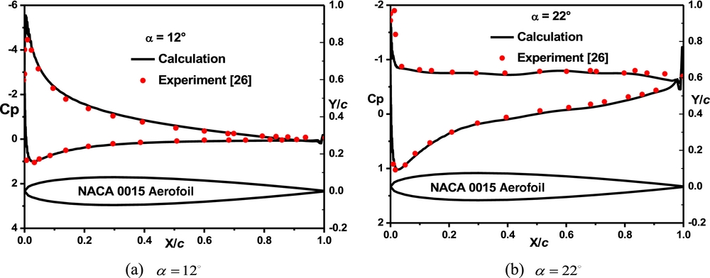
Figure 3. Pressure distributions of NACA0015 aerofoil at different angles of attack. (a) α = 12° (b) α = 22°.
Figure 4 shows the modified aerofoil of NACA0015 with a synthetic jet. The synthetic jet actuator is implemented at the leading edge of the aerofoil with the width of 0.14% chord length. In the experiment, the direction of the jet is normal to the surface of the aerofoil, and AoA of the aerofoil is 22°, and Re is 1.2 × 10⁶. Fig. 5 shows the vertical velocity profile in one synthetic jet period under a condition of Cu0 = 0 and Cum = 0.001 (U 0/U∞ = 0.6 and Um/U∞ = 0.6). Under the influence of the periodic movement of the synthetic jet, the velocity near the leading edge changes obviously with the time. The mixing between the internal and external layers of the flow in the boundary layer was heightened, and the energy of the boundary layer was strengthened at the same time. These two effects are useful for the inhibition of the flow separation and the increment of the lift force.
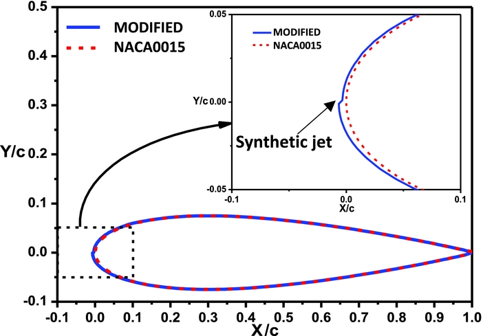
Figure 4. Modified NACA0015 aerofoil with the synthetic jet.
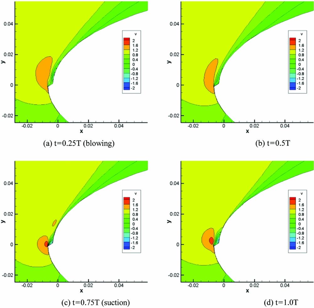
Figure 5. Vertical velocity profile in one synthetic jet period. (a) t = 0.25T (blowing) (b) t = 0.5T (c) t = 0.75T (suction) (d) t = 1.0 T.
Figure 6 shows the effect of Cum on the lift coefficient increment (ΔCl). As can be seen, the lift coefficient increment increases with the increase of Cum, and it is similar to the variation of experimental data. In addition, the numerical results are better than those from reference(Reference Donovan, Kral and Cary26).
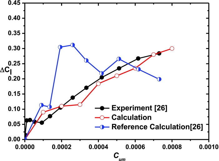
Figure 6. Effects of Cum on the lift coefficient increment of the aerofoil.
3.2 Verification of aerodynamic characteristic of rotor in forward flight
The Caradonna-Tung (CT) rotor(Reference Caradonna, Laub and Tung27) has two rectangular blades with a conventional NACA 0012 aerofoil, and the aspect ratio is 6. The CT rotor is used to investigate the effects of the synthetic jet on the rotor blade in forward flight. Four jet actuators are fitted on the upper surface at different positions as shown in Fig. 1. The actuators (A1, A3) are placed at 10%c on the suction surface while the other ones (A2, A4) are placed at 50%c, and the width of the jet orifice is 1%c as indicated in Table 1.
Table 1 The Position of Actuators on the Surface of the Blade

The grid of the blade has a resolution of 343 × 40 × 131, and there are 137 points on the lower and upper surfaces of the blade section, 11 points over the jet orifice. The baseline case for this rotor under a condition of M tip = 0.628 and μ = 0.3 is calculated first. Figure 7 shows the pressure distribution on the blade section at a collective pitch of 8°. As can be seen, the numerical results present a good agreement with the data obtained from Ref. (28).

Figure 7. Pressure distributions on different blade sections. (a) r/R = 0.8, ψ = 90°; (b) r/R = 0.8, ψ = 270°; (c) r/R = 0.96, ψ = 90°; (d) r/R = 0.96, ψ = 270°.
3.3 Effects of synthetic jet location
The control effects of the synthetic jet on the aerodynamic characteristic of rotors with different synthetic jet locations are investigated (M tip = 0.628, μ = 0.3), and the excitation frequency is F+ = 10.
Figure 8 shows the control effects of the synthetic jet on the normal force coefficient at a collective pitch of 8°. The steady component of the momentum coefficient is Cu0 = 0, and the unsteady component is Cum = 0.004 (Um/U tip=1), and the jet angle is θ jet = 25°. As seen in the figure, the synthetic jet has a significant effect on the sectional normal force coefficient of blades. The synthetic jets induced by actuators A2 and A4 are more efficient than those by actuators A1 and A3.
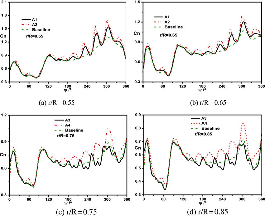
Figure 8. Comparisons of the control effects of different actuators on the sectional normal force. (a) r/R = 0.55, (b) r/R = 0.65, (c) r/R = 0.75, (d) r/R = 0.85.
The control effects of the synthetic jet on the lift coefficient of the blade at different collective pitches are illustrated in Fig. 9. The synthetic jet induced by actuator A4 is more efficient on enhancing lift than other actuators at the collective pitch of 8°, since there is no flow separation on the blade surface. When the collective pitch is 16°, the control effect of actuator A3 is the best, followed by A2. As a result, the synthetic jet located in the middle along the chordwise direction has a better effect at a smaller collective pitch, and the synthetic jet near the leading edge has a better effect at a bigger collective pitch.
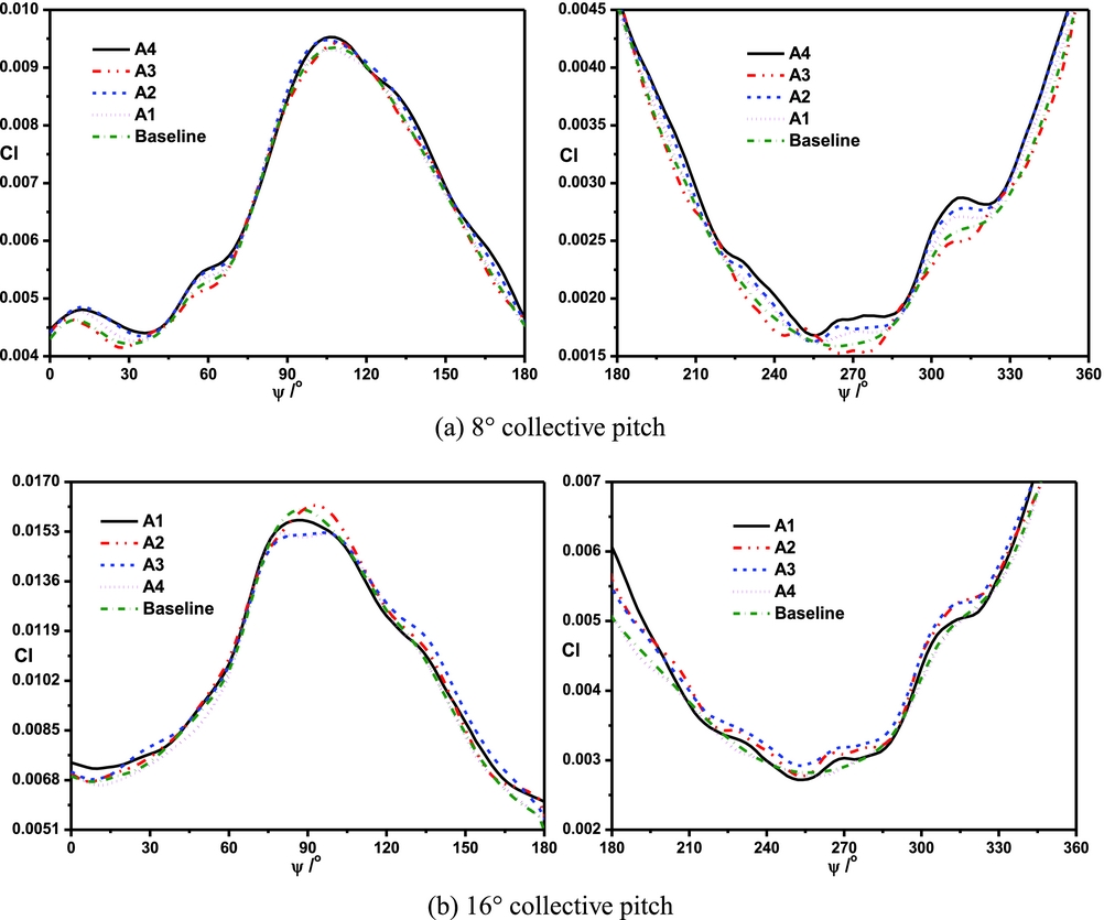
Figure 9. Comparisons of the control effects of different actuators on the lift coefficient of the blade. (a) 8° collective pitch, (b) 16° collective pitch.
Figure 10 shows the sectional pressure coefficient of the rotor blade with different actuators at a collective pitch of 16°. The synthetic jets (A1 and A3) near the leading edge of the blade have a more obvious effect on the disturbance of the pressure gradient. They can effectively weaken the strength of the shock wave. The synthetic jets (A2 and A4) located in the middle along the chordwise direction affect the pressure coefficient in a wider scope. They may decrease the adverse pressure gradient, and the flow separation can be delayed.
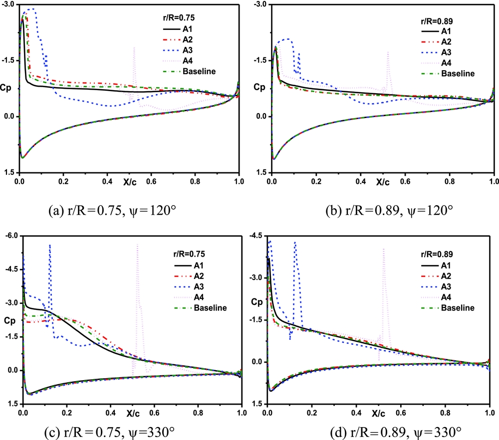
Figure 10. Comparisons of the sectional pressure coefficient with different actuators at a collective pitch of 16°. (a) r/R = 0.75, ψ = 120°; (b) r/R = 0.89, ψ = 120°; (c) r/R = 0.75, ψ = 330°; (d) r/R = 0.89, ψ = 330°.
The streamlines over the r = 0.8 R blade section at the 90° azimuthal angle are illustrated in Fig. 11. It can be seen that there is a large flow separation at the upper surface due to the increase of the adverse pressure gradient caused by the shock wave. Under the control of actuator A1 (or A2), there is still a flow separation on the upper surface, since 0.8 R section is outside of its control area. Under the control of actuator A3, the area of flow separation region is reduced. Under the control of actuator A4, the synthetic jet has a better effect on preventing the flow separation. It is because that the actuator A4 is located in the flow separation region. In addition, the best control effect on preventing flow separation could be obtained if all actuators work.

Figure 11. Streamlines over the r = 0.8 R blade section at 90° azimuthal angle. (a) baseline, (b) actuator 1, (c) actuator 2, (d) actuator 3, (e) actuator 4, (f) all actuators.
The streamlines on the blade surface at 90° azimuthal angle are shown in Fig. 12. It can be seen that the flow separation is obvious near the 90° azimuthal angle. Under the control of the synthetic jet, the stability of the boundary layer increases, and the local adverse pressure gradient decrease, and then the flow separation is inhibited.

Figure 12. Streamlines on the blade surface under the control of different actuators at 90° azimuthal angle. (a) baseline, (b) actuator 1, (c) actuator 2, (d) actuator 3, (e) actuator 4, (f) all actuators.
3.4 Effect of momentum coefficient
With the different momentum coefficient of actuators, the control effects of the synthetic jet on the aerodynamic characteristic of the rotor are investigated. Three typical momentum coefficients, Cum = 0.001 (Um/U tip = 0.5), Cum = 0.004 (Um/U tip = 1) and Cum = 0.009 (Um/U tip = 1.5), are employed. The jet angle is constantly equal to 25°.
Figure 13 shows the sectional normal force coefficient under the control of actuator A1 at a collective pitch of 8°. The synthetic jet has an obvious effect on the normal force in the retreating side, and the amplitude value and the average value of the sectional normal force increase with the increase of momentum coefficient.
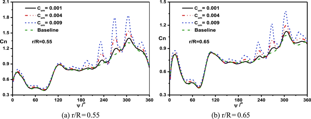
Figure 13. Comparisons of the sectional normal force coefficient with different jet momentum coefficients of A1 actuator at a collective pitch of 8°. (a) r/R = 0.55, (b) r/R = 0.65.
Figure 14 shows the sectional normal force coefficient under the control of actuators A2 and A4 at a collective pitch of 8°. Under the control of actuators A2 and A4, the average value of the sectional normal force significantly increases with the increase of the momentum coefficient. However, under the control of actuator A4, the oscillation of the sectional normal force decreases with the increase of the momentum coefficient.
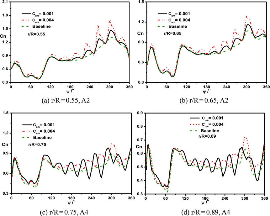
Figure 14. Comparisons of the sectional normal force coefficient with different jet momentum coefficients at a collective pitch of 8°. (a) r/R=0.55, A2; (b) r/R=0.65, A2; (c) r/R = 0.75, A4; (d) r/R = 0.89, A4.
Figure 15 shows the lift coefficient under the control of actuators A1 and A3 at a collective pitch of 8°. The variation of the momentum coefficient has a noticeable effect on the lift coefficient in the retreating side, and the lift coefficient obviously increases with the increase of momentum coefficient.
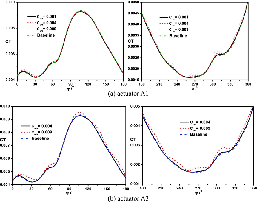
Figure 15. Comparisons of the lift coefficient with different jet momentum coefficients at a collective pitch of 8°. (a) actuator A1, (b) actuator A3.
3.5 Effects of synthetic jet angle
To investigate the influence of the synthetic jet angle on the control effect, the jet angles are selected as 5°, 25° and 45°. Figure 16 shows the sectional normal force of the blade with different jet angles under the control of actuator A1 at a collective pitch of 8°. There is a significant variation in the sectional normal force of the blade under the control of the synthetic jet, especially in the retreating side. In the retreating side, the average value and the amplitude value of the normal force obviously increase with the increase of the jet angle. As the jet angle changes from 5° to 45°, there is more energy of the synthetic jet into the boundary-layer flow, and the mixing phenomenon is more obvious.
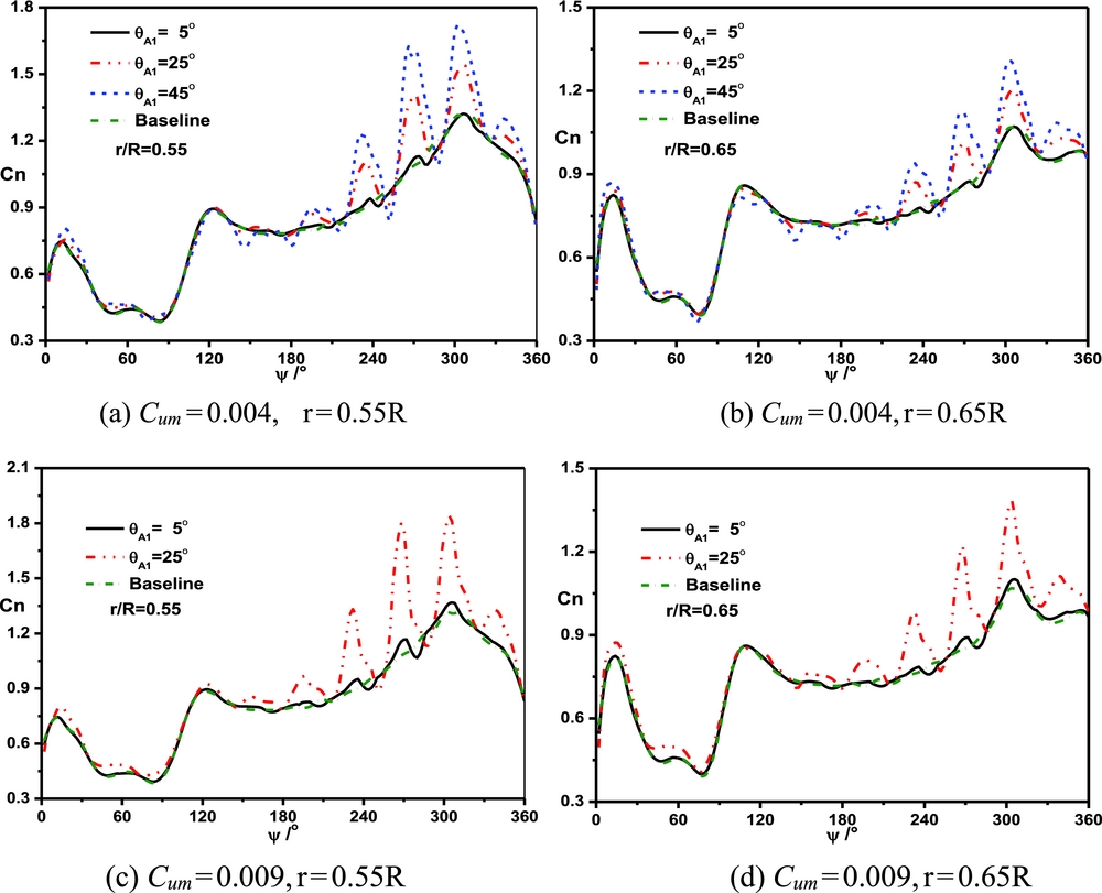
Figure 16. Comparisons of the sectional normal force with different jet angles of actuator A1 at collective pitch of 8°. (a) Cum = 0.004, r = 0.55R; (b) Cum = 0.004, r = 0.65R; (c) Cum = 0.009, r = 0.55R; (d) Cum = 0.009, r = 0.65R.
Figure 17 shows the sectional normal force of the blade with different jet angles under the control of actuator A1 at a collective pitch of 16°. When the jet angle is 45°, there is the most obvious effect on the normal force in the retreating side. Since the collective pitch is higher than that in Fig. 16, the phenomenon of the spanwise flow near the blade tip is more obvious, and the flow separation is possible in the retreating side. Therefore, a larger jet angle has a better control effect on the aerodynamic force of the blade at a large collective pitch.
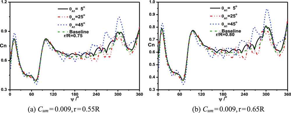
Figure 17. Comparisons of the sectional normal force of the blade with different jet angles of actuator A1 at a collective pitch of 16°. (a) Cum = 0.009, r = 0.55R; (b) Cum = 0.009, r = 0.65R.
Figure 18 shows the comparisons of the sectional pressure coefficient with different jet angles under the control of actuator A1 at a collective pitch of 16°. When the jet angle increases in a certain extent, the control effect on the sectional pressure coefficient is more obvious.
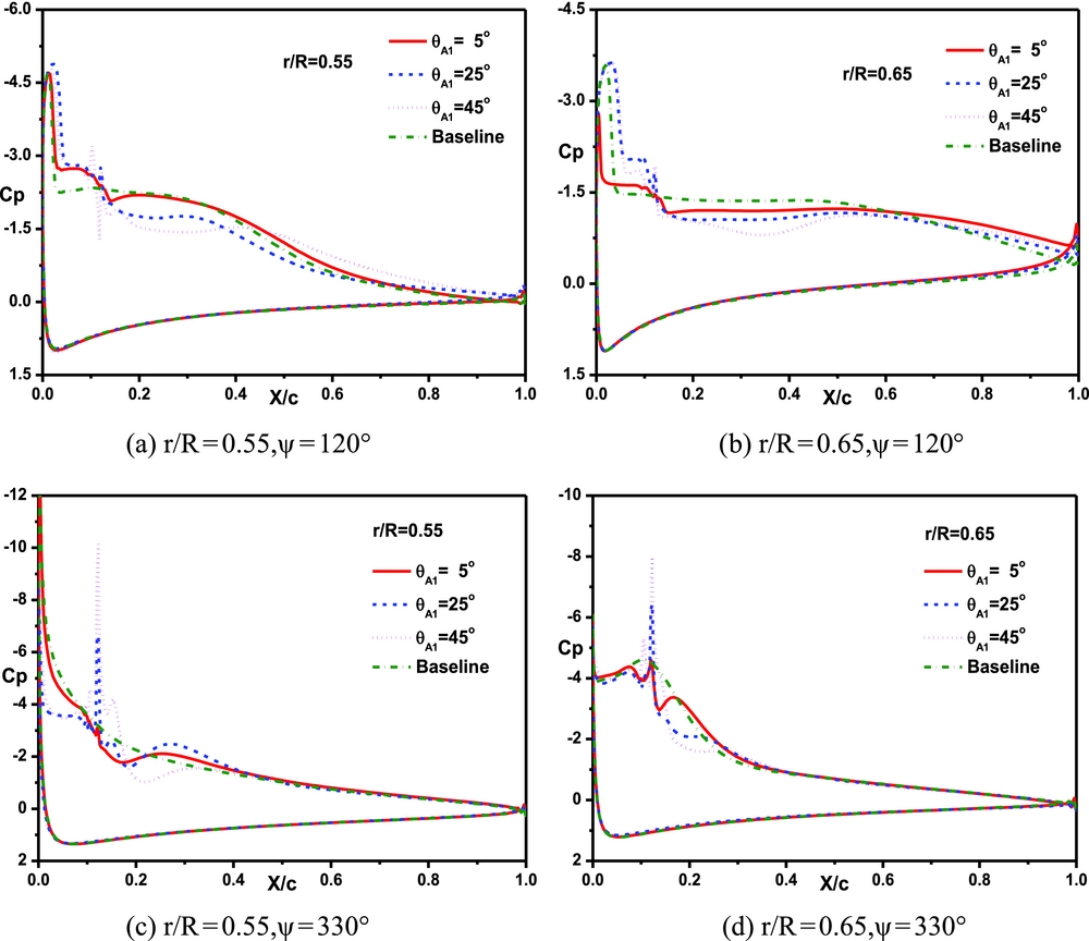
Figure 18. Comparisons of the blade sectional pressure coefficient with different jet angles of actuator A1 at a collective pitch of 16°. (a) r/R = 0.55, ψ = 120°; (b) r/R = 0.65,ψ = 120°; (c) r/R = 0.55,ψ = 330°; (d) r/R = 0.65,ψ = 330°.
3.6 Effects of synthetic jet array
Since the jet angle has an important effect on the aerodynamic characteristic of rotors, four jet arrays with different jet angles are investigated. The collective pitch is 16° and the jet momentum coefficient is Cu0 = 0, Cum = 0.009 (Um/U tip = 1.5). The different combinations of jet arrays are shown in Table 2.
Table 2 The Combinations of Jet Arrays
Figure 19 shows the lift coefficient of the blade with different jet arrays. Compared with the control effect under a single actuator, the control effect of a jet array on the lift coefficient is more obvious. All arrays can effectively enhance the lift coefficient of the blade, especially in the retreating side. In addition, array 4 has the best control effect on enhancing the lift coefficient, followed by array 2 and array 3.
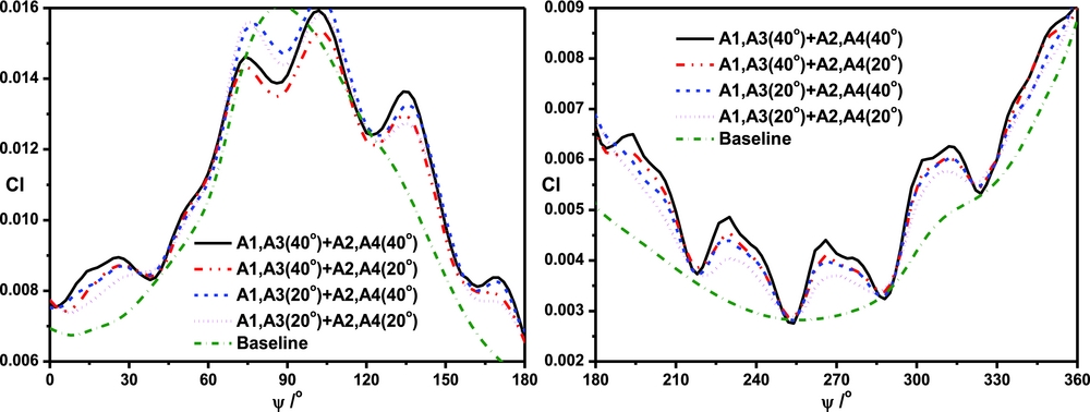
Figure 19. Comparisons of the lift coefficient of the blade with different jet array combinations.
Figure 20 shows the blade sectional normal force with different jet arrays. The normal forces at different sections are all enhanced by jet arrays. When the section is closer to the blade root, the ratio of the jet velocity to the sectional relative velocity is larger, and then the oscillation amplitude value of the normal force is larger. At the same time, array 4 has the best control effect on enhancing the normal force coefficient of the blade, which is coincident with that in Fig. 19.
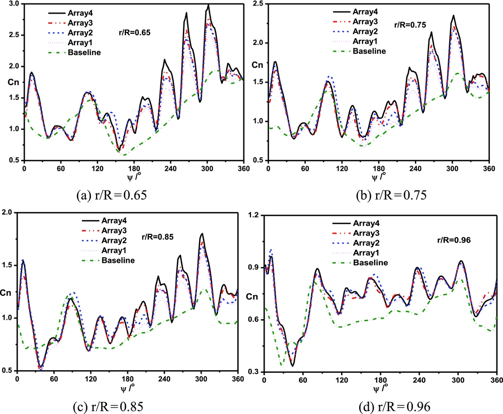
Figure 20. Comparisons of the blade sectional normal force with different jet arrays. (a) r/R = 0.65, (b) r/R = 0.75, (c) r/R = 0.85, (d) r/R = 0.96.
Figure 21 shows the pressure coefficient of the blade with different jet arrays at 120° azimuthal angle. As seen in the figure, there is an obvious variation of the pressure coefficient on the upper surface under the control of jet arrays. Since the adverse pressure gradient on the upper surface decreases, the flow separation may be inhibited, and then the blade sectional normal force increases. The jet caused by actuator A1 or A3 can effectively control the adverse pressure gradient near the leading edge, and the jet caused by actuator A2 or A4 can enlarge the pressure coefficient near the trailing edge.
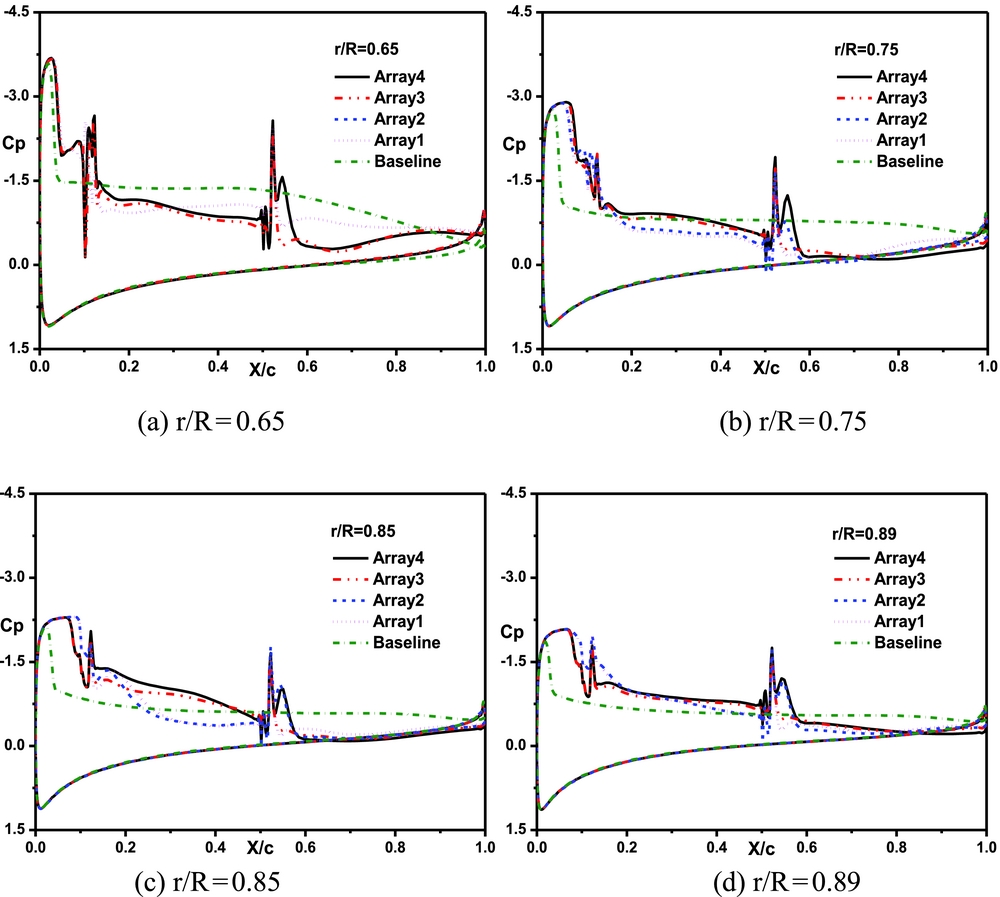
Figure 21. Comparisons of the pressure coefficient of the blade section with different jet arrays at 120° azimuthal angle. (a) r/R = 0.65, (b) r/R = 0.75, (c) r/R = 0.85, (d) r/R = 0.89.
Figure 22 shows comparisons of the pressure coefficient of the blade with different jet arrays at 330° azimuthal angle. Compared with the advancing side, the jet caused by A2 or A4 has a better control effect on the pressure coefficient of the blade surface, and the pressure coefficient near the trailing edge is almost the same as the baseline.
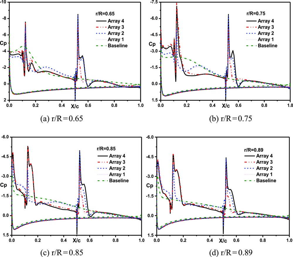
Figure 22. Comparisons of the pressure coefficient of the blade section with different jet arrays at 330° azimuthal angle. (a) r/R = 0.65, (b) r/R = 0.75, (c) r/R = 0.85, (d) r/R = 0.89.
4.0 CONCLUSIONS
Based on a numerical method for predicting the unsteady flowfield of the rotor, the control effects of the synthetic jet on the aerodynamic characteristic of the rotor in forward flight are effectively simulated and then parametric analyses are conducted. Some valuable conclusions are obtained as follows:
(1) The synthetic jet has the capability of improving the aerodynamic characteristic of the rotor, especially in inhibiting flow separation over the blade surface. The synthetic jet has a better control effect on the lift coefficient in the retreating side. The synthetic jet located in the middle of the aerofoil along the chordwise direction has a better effect on improving aerodynamic characteristics at a small collective pitch and the synthetic jet near the leading edge has a better effect at a large collective pitch.
(2) When the synthetic jet is in the middle of the blade, the oscillation amplitude value and the average value of the normal force both increase with the increase of momentum coefficient. When the synthetic jet is near the blade tip, the oscillation amplitude value decreases with the increase of momentum coefficient.
(3) In the advancing side, there is no obvious difference in the normal force coefficient among different jet angles. In the retreating side, the average value and oscillation amplitude value of the normal force coefficient increase with the increase of jet angle.
(4) Comparing with the single synthetic jet actuator, jet arrays have a better control effect on the aerodynamic characteristic of the rotor. In the retreating side, the lift coefficient of the blade increases with the increase of jet angles (15°-45°). The pressure coefficient of the suction surface could be totally affected by the jet array. The synthetic jet near the blade leading edge has an effective control on the adverse pressure gradient, resulting in the weakening of the shock wave. The synthetic jet located in the middle along the chordwise direction can increase the pressure coefficient near the blade trailing edge.


