NOMENCLATURE
- AIM
-
Advanced In-Flight Measurement Techniques
- AIM²
-
Advanced In-Flight Measurement Techniques 2
- ARC
-
airworthiness certificate
- DLR
-
Deutsches Zentrum für Luft und Raumfahrt e.V. (German Aerospace Centre)
- DMU
-
digital mock-up
- EASA
-
European Aviation Safety Agency
- FCL
-
flight crew licensing
- FEM
-
finite element method
- IPCT
-
Image Pattern Correlation Technique
- PIV
-
particle image velocimetry
1.0 INTRODUCTION
For decades, aircraft design has been divided into fixed, well-established phases and development steps. They stand the test of time with continuous advancement of tools. For example, intense flight testing of all new aircraft models is of major importance. To keep up with the latest technology, the goals, scope and methodology have changed a lot, but the general purpose of airworthiness approval is unchanged and indispensable(Reference Stinton1). Contemporary design processes are closely connected with economic factors such as environmental awareness, fuel efficiency and durability of the airframe as well as shareholders’ benefits. Therefore, the demand for an increasing payload-to-basic-mass ratio is still crucial. New strength and structural solutions allow a better utilisation of material properties which results in an optimised gross weight as well as in improved stability and reliability(Reference Niu2). One may thus presume that flight testing of an aircraft verifies structure and mass design amongst many other features(Reference Norton3).
Experimental verification of structural solutions is essential during the certification process in general. Therefore, the quantities measured as well as the measurement method and its accuracy, explicitness and mutuality during the experiment determine the final success. Concerning structure assessment an important group of parameters measured are deformations that provide information about the stiffness directly and about the stress state by using the constitutive model of the structure.
Deformations can be measured as:
-
• Displacement of certain points in defined directions
-
• Displacement of the plane or surface
-
• Strain in certain points or as a field of strain
-
• Acceleration of certain points in defined directions
Modern measurement techniques, the capability of gathering bulk data, transferring and processing data on line enable in-flight studies of phenomena or aircraft behaviours that were barely possible or significantly limited by weak hardware performance in earlier times. The stress state analysis under flight loads mentioned above is one example. The most common tools applied for many years have been strain gauges or accelerometers(Reference Hoffman4). The diagnostics of laminar composites introduced optical fibre gauges(Reference Chehura, James, Tatam, Lawson and Garry5). Nevertheless, none of these methods was able to identify extensive structural stress fields. This disadvantage could be overcome by the analysis methods based on digital image processing. Industrial applications of 3D scanners for surface shape or deformation measurements also became a useful and popular tool, especially for quasi-static investigations. One of the first attempts at in-flight application is a method called Image Pattern Correlation Technique (IPCT), introduced by Klinge et al(Reference Klinge6,Reference Kompenhans, Schroder, Engler, Klinge and Stasicki7) of the German Aerospace Centre (DLR).
IPCT is an optical, non-intrusive measurement technique based on photogrammetry in combination with modern correlation algorithms developed for Particle Image Velocimetry (PIV). The simplest IPCT set-up consists of one monochrome camera observing an object covered with a random dot pattern. Using image pairs of the randomly patterned object acquired by a stereoscopic camera system, its 3D position and shape can be directly measured. The significant advantages of the stereoscopic approach are that the 3D position can directly be triangulated (no constraints and models are needed), and the images of both cameras taken at the same instant of time are dewarped and correlated. Thus, a rotation of the pattern (e.g. caused by aileron deflection) will not cause any problems because the pattern has the same orientation in both images. An example of two installations for different wing areas of a large airliner is shown in Fig. 1 (Reference Boden, Kirmse, Weikert, Wolf, Petit and Jentink8).
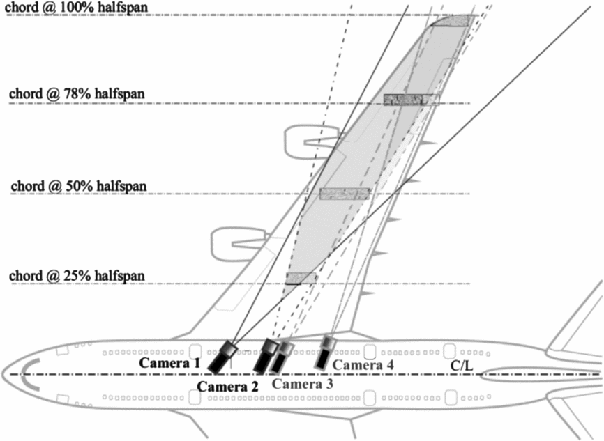
Figure 1. Application example of two stereoscopic IPCT camera sets placed in the fuselage of a large airliner for wing deformation measurements.
The functionality of the stereoscopic IPCT approach for 3D surface shape registration is shown in Fig. 2. The surface to be investigated with a random dot pattern is recorded by two cameras at the same instant. Both cameras cover at best a congruent area of interest with similar fields of view but under different viewing angles. The images of both cameras are dewarped in a way that both cameras seem to look from the same point of view. Then a cross-correlation algorithm identifies the image coordinates of areas with matching dot pattern in the images of camera 1 (coordinates x 1, y 1) and camera 2 (coordinates x 2, y 2). With known intrinsic parameters (e.g. focal length, distortion, principal point) and extrinsic parameters (position and orientation) of both cameras, the real 3D coordinates of the processed dot pattern area are determined by means of central projection and triangulation. Applying this procedure to all pattern sections in the stereo image pair depicting the same dot pattern region on the surface finally yields to a highly accurate reconstruction of the complete observed 3D surface.
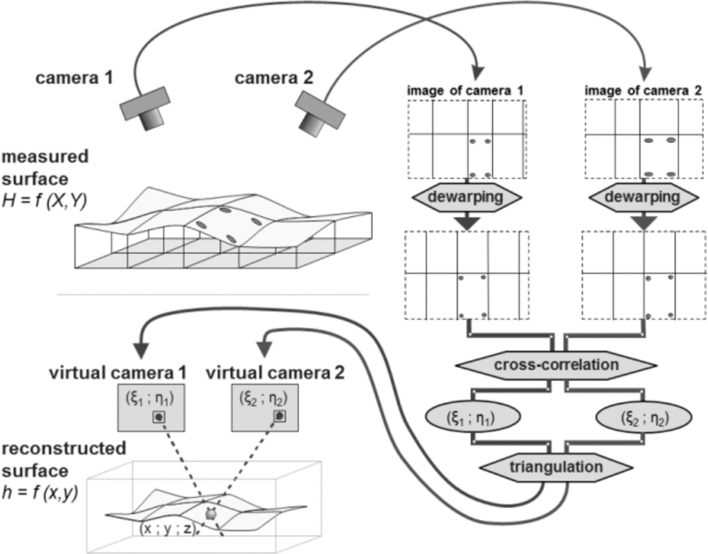
Figure 2. IPCT processing flow.
Structure deformation is calculated using the IPCT tool in two subsequent time steps as described above. The deformation form is obtained by comparing the digital surface of the deformed state to a reference state (undeformed or not). Exemplary measurement results of the wing deformation for the application illustrated in Fig. 1 is presented in Fig. 3.
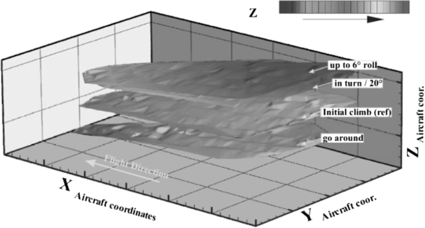
Figure 3. Wing-tip displacement of a large aircraft in different flight conditions.
The development of IPCT with multiple application examples mainly took place within the framework of the two subsequent research projects co-funded by the European Commission – Advanced In-Flight Measurement Techniques (AIM) and Advanced In-Flight Measurement Techniques 2 (AIM²) coordinated by the DLR(Reference Boden, Lawson, Jentink and Kompenhans9). Before the first AIM project, the method matured from laboratory to ground and then in-flight applications. Within the projects and several supplementary tasks, the measurement scenarios covered topics such as wing and aileron deflection of a glider, a commuter-class aircraft and a large airliner; wing vibration and flutter; main rotor blade deformation of a helicopter; and propeller blade deformation. During more than 10 years of continuous progress, software dedicated to the specific in-flight conditions has been developed that also covers procedures for hardware selection (cameras, lenses, etc.), installation issues, and digital marker and pattern design as well as investigations of illumination conditions. Finally, the IPCT measurement method has been proven to be an off-the-shelf tool for engineering purposes in an industrial environment.
One of the scientific tasks within AIM² was to create a feedback between real measured in-flight structure deformations of an aircraft and corresponding numerical stress and strain calculations received during the preliminary design phase. In the following step, the necessity and usefulness of such feedback had to be assessed. In this research program, the tools used for structure deformation measurements in flight conditions was the image-based IPCT method; for numerical structure design, the finite element method (FEM) was used.
This paper presents the outcomes of a flight test campaign in AIM² concerning application of IPCT for wing deformation measurements on a composite training glider as a source of numerical data for FEM calculations. All previous IPCT flight tests were performed with motorised and more or less spacious aircraft, providing an additional power supply for experimental installations. The airworthiness of the aircraft obeyed special regulations for prototypes, making the certification easier in most cases. The main purpose of the glider testing presented in this contribution lies in proving IPCT under conditions never tried before with limited space and power on an aircraft taken straight from the hangar. This experiment is intended to be a representative example of an engineering application scenario.
The next section describes the test aircraft and the measurement installation. The following section concentrates on the flight test campaign as well as certification and operational issues. Several measurement examples are presented in section 4. The last sections are focused on the future work and lessons learned from this research program.
2.0 PW-6U FLYING TEST BED
2.1 The airframe
Initially we planned to use the research aircraft AOS-71 electric glider when the AIM² project proposal was submitted. This carbon-epoxy aircraft is a joint project of the Rzeszów and Warsaw Universities of Technology. Moreover, the electric glider AOS-71 was intended to be used as a multipurpose flying test-bed because in its original factory configuration, it is already equipped with special joints for external installations. Due to a continuously increasing delay in the AOS-71 program schedule that may have interfered the progress of the AIM² project, the test bed was replaced by the PW-6U two-seated training glider. This aircraft, which is basically identical to the AOS-71 electric glider but unpowered, was designed as flying test bed as well and is equipped with special joints for additional external installations.
The research glider PW-6U was modified to carry additional equipment for measurement and recording. The cameras for IPCT imaging, for example, were elevated over the centreline of the fuselage and installed in a specially designed housing attached to the fuselage by a vertical pod, as presented in Fig. 4 (right).

Figure 4. Electric glider AOS-71 (left) and the unpowered glider PW-6U with dorsal camera pod (right).
2.2 IPCT measurement installation
Aiming for a global wing deformation measurement to match and compare the results with FEM calculations, a stereoscopic IPCT installation was chosen. Special boundary conditions linked to the use of a glider as a test bed strongly influenced the IPCT setup design in terms of miniaturisation, simplicity and power management.
A Digital Mock-Up (DMU) and accuracy estimations according to Kraus(Reference Kraus10) were used for a virtual predefinition of all relevant camera system parameters such as camera type, lenses, position and alignment. Therefore, boundaries such as physical aptitude, availability and structural limits had to be taken into account. Also, the random dot pattern was designed virtually using the DMU model. Before printing, the measurement setup was tested in virtual reality(Reference Szczerba, Szumski and Kucaba-Piętal11). All relevant design parameters of the PW-6U IPCT installation are presented in Table 1.
Table 1 Feature summary of the stereoscopic IPCT installation for the PW-6U glider
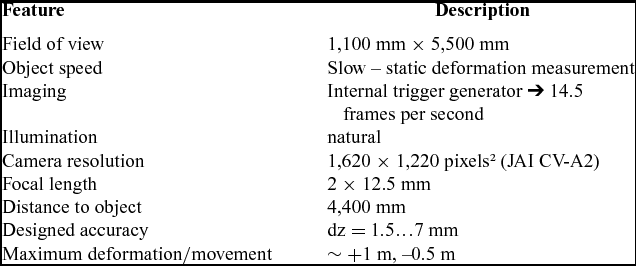
The image recording installation was placed in two locations inside the airframe. Both cameras were housed in a fairing on top of the pod derived from the geometry of the optical system defined by DMU studies. The camera control and recording computer and the separate power supply were attached to the wooden rig in the rear cabin with the pilot seat removed. Electric and data transfer wiring were passed inside the pod.
Measurement of structure deformation based on comparison of subsequent airframe positions requires dedicated surface preparation. This IPCT pattern consists of two components. There is the random dot matrix, defined by dot size and its perspective stretch factor as well as the distribution density. This dot pattern is supplemented with a grid of 20 to 50 checkerboard markers from which the grid and marker dimension properties have to be acquired. Figure 5 (left) shows the applied IPCT pattern on the port wing of the test bed. Despite the loss of extensive surface information, the marker grid could also be used as a stand-alone target method as it is well known for common 3D position detection.

Figure 5. Dot pattern and markers on the wing (left) and recording hardware stored in the rear cabin (right).
The installation was supplied by a dedicated flight data recorder and remote control panel for the test pilot(Reference Kopecki and Rzucidło12). In Fig. 5 (right), the cabin installation with control computer, power supply, flight data recorder and wiring is shown.
3.0 FLIGHT TESTING – CERTIFICATION AND OPERATIONS
3.1 Initial preparations
Prior to the first flight test the modified glider underwent a series of ground tests to prove the reliability and strength of the proposed solution. Figure 6 depicts the test bed during a static test (left) and a wind tunnel test (right).
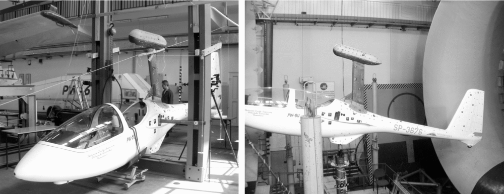
Figure 6. Static tests (left) and wind tunnel tests (right) were performed to prove the stiffness, strength and stability of the camera pod.
The static ground test of the camera pod included five critical load cases identified as boundaries of the reduced flight envelope according to CS-22 requirements for gliders(13). The main objective of the test was a deformation measurement of the pod structure and an overall reliability assessment. The results demonstrated that there were no significant or unexpected deformations. Moreover, no damage to the structure was identified.
Aerodynamic ground tests were performed in the wind tunnel T-3 (nozzle diameter of 5 meters) of the Institute of Aviation in Warsaw, Poland (ILOT). The main goals were to find force and moment changes on the glider fuselage and to quantify the influence of the pod on the directional stability. The fuselage with the pod had to undergo a series of tests with different airflow velocities, angles-of-attack, angles of sideslip and rudder deflection angles. The range of the airflow velocity varied from 34 m/s to 40 m/s. All relevant forces and moments were recorded by a strain gauge based aerodynamic weighing device for five components. The angle-of-attack varied from α = –2° to +15° (1° step). During the tests, no behaviour occurred that would have disqualified the modified glider as not being airworthy.
Before the first flight, the ready-equipped glider including the pod and all installations on board were submitted to several ground rolls towed by a car up to lift-off speed.
3.2 Airworthiness
The PW-6U glider type designated as a test bed belongs to an organisation that performs certified training. The type certificate is recognised by the Polish national aviation authorities under local regulations. Although the structure was produced according to the prototype documentation with all additional reinforcement for external installations the scope of an Airworthiness Certificate (ARC) does not allow using them without permission. Therefore, the glider was temporarily moved to the category Specjalny (this means ‘special’ in Polish, a category for the aircraft with no type certificate and maintained only by the owner, which is very common for rare or vintage models). After that, all modifications were permitted and supervised by a local authority inspector. What is more the category change process turned out to be reversible. With minor structure repairs the glider regained its initial type certificate after the flight test campaign. So far this is the only known certificate recovery in Poland because usually a type certificate once lost is irrecoverable.
3.3 Crew requirements
The selection of an appropriate and approved test pilot was one of the most time-consuming issues during this research program and caused almost 2 years of delay in the project schedule. In total three fatalities happened that were not directly connected with the project.
During the project duration European countries which are members of EASA were working on a transition of requirements in the field of flight crew licensing. The final date of this PART-FCL implementation in Poland was fixed for 8 April 2014 which became vital for the successful project finalisation. Prior to this date, all flights planned in the project could only be performed by a glider test pilot.
All preparations for flight testing – including proof of airworthiness, the authorisation of the test program and the crew selection – were accomplished by May to June 2013. Unfortunately, the test pilot dedicated to this campaign died in a fatal accident while testing another aircraft in mid-June 2013. A subsequent test pilot was engaged in the AIM² project for PW-6U testing. First assessment flights were scheduled for mid-August 2013. Two days before the planned first flight, another PW-6 glider crashed, killing a student and seriously injuring an instructor. The authority immediately grounded all gliders of this type and demanded special mandatory maintenance of the empennage, which was suspected to be the cause of the crash. Hence, the completely ready flight test installation had to be refurbished, the glider was sent to the producer and all test activities had to be postponed until 2014. In between, the actual AIM² PW-6U test pilot died in a fatal crash with another glider in November 2013.
A new qualified test pilot had to be quickly found during wintertime. Luckily the Polish authorities, by introducing new licensing regulations, had eased the respective pilot requirements in the meantime. According to the PART-FCL they approved an experienced glider flight instructor as a test pilot for the whole AIM² flight test program, except for the first flight. The latter had to be performed by a former glider test pilot.
3.4 Test flights
All flights were performed using the research aircraft PW-6U glider, reg. SP-3676 with the towing aircraft Zlin Z-242L, reg. SP-TZZ. The pilot held a glider license with instructor rating and had the required experience on the PW-6 type. The first two certification flights were carried out by a glider test pilot. All flights took place on the EPRJ airfield with asphalt runway within the controlled airspace of the EPRZ international airport.
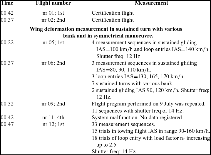
The test program included several tasks such as checks of the flight data recorder system, deformation measurements in sustained gliding flight, deformation measurements in sustained symmetrical manoeuvres and deformation measurements in turns. The complete log book is presented in Table 2.
Table 2 IPCT test flight log book
4.0 RESULTS AND DISCUSSION
A look at the raw data of the IPCT image recording revealed a promising foundation of about 75 gigabytes of high-quality stereo images. A good congruence between virtually designed and the real-field of view of the cameras indicated the sophistication of the holistic setup design process using the experience gained during former IPCT application scenarios (IPCT pattern visible in the left part of Fig. 7 not in final position).

Figure 7. Comparison of virtual (left) and real (right) field of view of one IPCT camera.
The images recorded in flight were of good quality in terms of illumination, pattern reflectance and contrast, which is a vital requirement for a reliable IPCT evaluation. The only areas in the field of view of the cameras that can be processed are:
-
• prepared with the IPCT dot/marker pattern, and
-
• recorded by both cameras at the same instant of time.
This is why all other parts of the image are masked out to ease the multi-pass mapping strategy implemented to the IPCT cross-correlation software.
For time synchronisation purposes with parameters of the flight data recorder, each image pair is logged with GPS information such as time stamp and position. This enables a dedicated data processing of single manoeuvre or a series of interesting manoeuvres.
First of all, the applied grid of integrated checkerboard markers was evaluated using a special edge-detection algorithm that provided first local surface information and was used as starting point for further evaluation steps. This advanced the processing of the dot pattern remarkably. In order to match the IPCT data with FEM calculations, all evaluation results were transformed to a Cartesian wing coordinate system which had its origin at the leading edge 10 mm off the root connection to the fuselage (i.e. no standard aircraft coordinate system).
During the design phase of the IPCT setup, the installation parameters were balanced between structural constraints and accuracy requirements. Figure 8 (left) shows the estimated measurement error according to Kraus(Reference Kraus10) for the stereoscopic setup with a varying base distance (sensor camera 1 to sensor camera 2). The stereoscopic base width was thus set to 1 m, with an expected accuracy of the system between 1.5 mm near the cameras up to 7 mm at the wing tip (see also Table 1). For the real measurement, it was not easy to determine error values, but a good indication for at least the systematic error part provides the averaging of a number of static on-ground recording results. This has been done for 100 samples and is illustrated in Fig. 8 (right). A partitioning reference into the root and tip section is given in Fig. 7 (right).
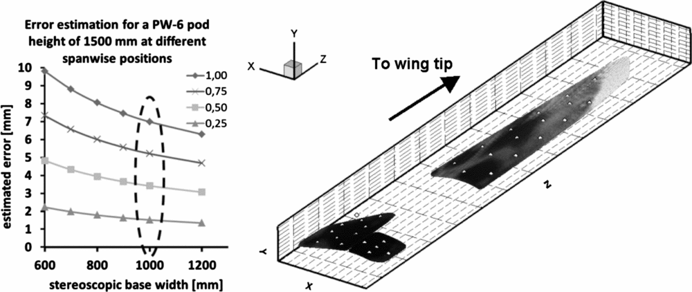
Figure 8. Theoretical error estimation in the spanwise direction for different distances between two cameras (left); processed ground shape recording of the port wing overlaid with a greyscale code for standard deviation of 100 averaged IPCT image pairs; the darker the better (right).
The greyscale in the right part of Fig. 8 pertains to the Standard Deviation (SD) of 100 averaged image pairs that were recorded in a levelled static on-ground condition as a reference during the calibration procedure. Darker areas in the root section represent SD values better than 0.5 mm whereas higher SD values towards the wing tip rise up to approximately 5 mm at most and appear in lighter grey nuances. Thus, the error values for this measurement are within the theoretically estimated range and testify reliable IPCT results.
In Fig. 9, an exemplary IPCT result is presented. The depiction shows the wing shape of the glider for two different load cases measured with IPCT. A wing deformation of about 360 mm at the wing tip was determined comparing the reference on-ground shape (dark with white marker positions, see also Fig. 8) with the wing shape during a manoeuvre with a constant vertical acceleration of approximately 1.8 g (light with black marker positions). Regarding the measured deformation magnitude of several hundred millimetres leads to a relative accuracy of better than 2%.
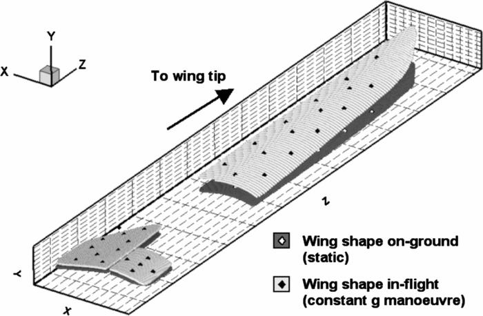
Figure 9. Representative IPCT result comparing the shape of the port wing on-ground (dark with white marker positions) with the wing shape during a manoeuvre with constant vertical acceleration (light with black marker positions).
Further post-processing steps are, firstly, a projection of the in-flight measurement results to the reference ground shape to calculate a comprehensive deformation distribution. Secondly, a transfer of these effective deformation data to a meshed FEM node grid links the IPCT measurement results with the respective numerical FEM model of the glider wing.
The scientific flight test campaign presented in this paper was focussed on the assessment of a new application scenario for the deformation measurement method IPCT. In order to realise this project, several challenges were successfully undertaken. On one hand, a class of aircraft like the composite training glider PW-6U had not been examined with IPCT before, and this type of aircraft initially was not dedicated to research. Also, most of the researchers had to be trained, as the team had had no experience with the measurement method. The results of the PW-6U test campaign proved the reliable applicability of IPCT for test beds of this category.
5.0 POTENTIAL FOR FURTHER WORK
The present and preceding research projects aiming at in-flight displacement and deformation measurements using the modern method IPCT proved its reliability and feasibility for industrial applications. Now, further fields of application using the miniaturised IPCT setup can be covered where the control computer has to be small and energy-saving and can be autonomously powered with a separate battery. Further development potential lies in two branches of IPCT. On one hand, the miniaturised system could be adapted to cameras with better performance in terms of resolution, frame rate, sensor sensitivity and image quality in general. On the other hand, the robust post-processing algorithms can be enhanced; they work reliably but are relatively slow and do not include timeline correlation yet.
These particular measurements on a glider provided wing deformation data for further analysis of the composite structure. The authors proposed an advanced approach for aircraft structure analysis by combining optical deformation measurement data gathered in-flight with a numerical FEM model.
The algorithm of data transfer between the IPCT post-processing software and the Finite Element Method pre-processor enabled to associate a 3D IPCT result with the nodes of a corresponding finite element mesh. Therefore, the stress or strain distribution in the structure as a result of initial deformation corresponds to the in-flight conditions. The detailed description of this procedure will be addressed in subsequent publications.
6.0 LESSONS LEARNED
Although this was not the first flight test campaign in their research history, the one presented in this paper was a challenging task for both partners the Rzeszów University of Technology and the DLR. The experience gained during this collaborative research program allowed to identify issues, procedures or other relevant events that should be taken into account for following activities of this type. Both the positive achievements as well as threats or inconveniences became vital lessons for the team, worth to be mentioned for the respective research community. The most numerous remarks concern the preliminary preparations and operational matters. Some of them are connected to the flying test bed itself. The following conclusions of this project are sorted into three categories:
⇑ = worth repeating in further campaigns
⇔ = might be considered in cases of precaution or doubt
⇓ = threats or issues that should be avoided
⇑ A significant distance between partner sites and a limited number of bilateral meetings had no influence on the project performance. Electronic media allowed us to transfer bulk data and to communicate in real time without delay. Furthermore, these factors disciplined the team members to make dependable preparations and work time-effectively.
⇑ The flight trials were located in a C-class controlled airspace of an international airport with traffic of medium density. Proper pre-planning with air traffic controllers and coordination of research sorties with scheduled and unscheduled flights prevented delays within the program.
⇔ The airfield of the Rzeszów University of Technology has an asphalt runway with taxiways, aprons and hangars. Usually gliders operate from small grass airfields. In contrast, research flights with tiny and sensitive metrology installations demand a convenient environment with a maintenance hangar and hardened pavements. Therefore, the number of possible locations might be limited significantly.
⇔ A towing aircraft is a requirement for glider flight testing.
⇔ A chase aircraft might be considered as an additional element of the recording system, but here it was used for observation and photo documentation matters only.
⇓ The work load, number of required crew members and individual effort for flight testing with a glider is relatively high compared to the reduced complexity of a glider itself. Campaigns with powered aircraft seem to be easier to coordinate and perform.
⇓ The flying test bed should be chosen carefully. Planning a program with a not-yet-ready prototype is risky and may cause unexpected delays or cancellations.
⇓ Changes in certification and licensing requirements always generate irritating delays, especially when authorities do not have respective procedures in place. In this program, the interpretation for an approved pilot alone took half a year.
7.0 CONCLUSIONS
This paper presents an exemplary industrial application of a promising optical metrology. The typical task of experimental verification of the structure stiffness and strength has been solved. Using the digital image correlation method IPCT, the wing structure deformation was measured. Therefore, the following summary of this flight test campaign can be stated:
-
• The design and preparation of the measurement setup for the composite glider were based on solutions and procedures derived from experience gained during previous measurement campaigns. Although the aircraft might be considered as generally not dedicated to flight testing, no unexpected technical difficulties were encountered during the task.
-
• The hardware and software for data pre- and post-processing can be considered as off-the-shelf.
Concerning the previous statements, this example proves that stereoscopic IPCT has been developed to the level of research applications in an industrial environment as it was considered at the beginning of the AIM² project.
The results of the measurements in flight conditions allowed preparing essential data for further investigations of numerical airframe structure models. Nevertheless, some lessons learned should be kept in mind:
-
• The difficulties that generated the longest delays in the program schedule resulted from official requirements demanded by aviation authorities concerning examination of the test bed reliability and durability. Furthermore, the official requirements for the flight and ground personnel should be figured out well beforehand.
-
• The change of the test platform from the not-ready prototype to a series aircraft took 1 year.
The effective amount of time for preparation and testing turned out to be relatively small, but it was multiplied by certification issues.
ACKNOWLEDGEMENTS
The work and results presented in this paper were co-financed by the European Commission, 7th Framework Program within the AIM² (Advanced In-Flight Measurement 2) project, Grant Agreement 266107.


