


1. Introduction
Structures where cross-cutting elements (CEs; or transecting elements or TEs as per Grasemann & Stüwe, Reference Grasemann and Stüwe2001) cut across host-fabric elements (HEs) and drag the HE near the CE in rocks have been described collectively as flanking structures (FS; Passchier, Reference Passchier2001).
These structures have also been described as drag folds (Hills, Reference Hills1953), roll-over anticlines (Hudleston, Reference Hudleston1989; Reches & Eidelman, Reference Reches and Eidelman1995; Kocher & Mancktelow, Reference Kocher and Mancktelow2005; Spahić, Grasemann & Exner, Reference Spahić, Grasemann and Exner2013), fringe folds (Grasemann, Fritz & Vannay, Reference Grasemann, Fritz and Vannay1999) and flanking folds (Grasemann & Stüwe, Reference Grasemann and Stüwe2001). Additional points regarding the concept of FS are: (1) the CE can rotate by bulk deformation (Grasemann, Stüwe & Vannay, Reference Grasemann, Stüwe and Vannay2003; Exner, Mancktelow & Grasemann Reference Exner, Mancktelow and Grasemann2004; Wiesmayr & Grasemann, Reference Wiesmayr and Grasemann2005); (2) drag folds can occur in the footwall blocks; (3) drag folds of FS do not require ramp and flat geometry of the CE (Wiesmayr & Grasemann, Reference Wiesmayr and Grasemann2005); (4) these structures were used to determine shear sense with caution (Grasemann, Fritz & Vannay Reference Grasemann, Fritz and Vannay1999; Passchier Reference Passchier2001; Mukherjee & Koyi, Reference Mukherjee and Koyi2009; Mukherjee, Reference Mukherjee2010a , Reference Mukherjee b , Reference Mukherjee2013a –d); and (5) FS can also be used to deduce shear strain (e.g. Mulchrone & Walsh, Reference Mulchrone and Walsh2006; Xypolias, Reference Xypolias2010). Furthermore, footwalls to natural faults need not always be rigid (Grasemann, Martel & Passchier, Reference Grasemann, Martel and Passchier2005). The concept of flanking structures therefore explores deformation of the footwall blocks.
All combinations of drag and slip of the HE near the CE are possible (Fig. 1; Exner & Grasemann, Reference Exner and Grasemann2010). A reverse fault-like shear of HE along the CE is called an s-type FS, and a normal fault-like shear an a-type (Grasemann, Stüwe & Vannay, Reference Grasemann, Stüwe and Vannay2003). Shear bands were also considered as FS (Grasemann, Stüwe & Vannay, Reference Grasemann, Stüwe and Vannay2003). Along the direction of the half arrows for individual FS in Figure 1b, if convex HE is reached, the sense of drag is referred to as normal; in the opposite case, it is referred to as reverse (Grasemann, Stüwe & Vannay, Reference Grasemann, Stüwe and Vannay2003). This work follows the terminologies of FS as presented in Passchier (Reference Passchier2001) and Grasemann, Stüwe & Vannay (Reference Grasemann, Stüwe and Vannay2003). Notice that s-type FS are also described as contractional, and a-types and shear bands as extensional (e.g. Grasemann, Stüwe & Vannay, Reference Grasemann, Stüwe and Vannay2003). When the shear sense on the CE corresponds with that of the regional shear sense, the FS has been described as co-shear slipped. Mismatched shear senses have been referred to as counter-shear slipped (Grasemann & Stüwe, Reference Grasemann and Stüwe2001; Grasemann, Stüwe & Vannay Reference Grasemann, Stüwe and Vannay2003; Coelho, Passchier & Grasemann, Reference Coelho, Passchier and Grasemann2005). For example, in Figure 1b the two s-type FS and the two shear bands are co-sheared. By contrast, the a-type FS are counter-sheared.
Figure 1. (a) Internal HE: dragged host-fabric element in contact with the cross-cutting element (CE). Away from the internal HE is the undeformed external HE. Reproduced with permission from Passchier, C.W. 2001. Flanking Structures. Journal of Structural Geology 23, 951–962, Elsevier. The internal HE is restricted within the internal HE zone. (b) Slip and drag senses of the HE where a top-to-right shear prevailed. Reproduced with permission from Grasemann, B. et al. Reference Grasemann, Stüwe and Vannay2003. Sense and non-sense of shear in flanking structures. Journal of Structural Geology 25, 19–34, Elsevier.
Drag of geological layers around cross-cutting objects is possible in several tectonic contexts, for example structurally controlled extrusion of low-density materials (Hudec & Jackson, Reference Hudec and Jackson2007) and folds associated with faults (Nemčok, Schamel & Gayer, Reference Nemčok, Schamel and Gayer2005). Koyi et al. (Reference Koyi, Schmeling, Burchardt, Talbot, Mukherjee and Sjöström2013) recently drew attention to examples where the CE (their ‘wake’) moves en mass and leaves behind a local wake of dragged markers. However, the present review is restricted to papers that specifically describe flanking structures (FS), and where the CE are mainly faults, fractures and veins.
The CE can be thin fractures, primary- (C-) and secondary shear planes (C′-, C″- as per Passchier & Trouw, Reference Passchier and Trouw2005), veins, cavities, leucosomes in migmatites, burrows in soft sediments, inclusions of minerals within other minerals and boudinaged clasts or dykes. The CE can also be a ductile fault zone where the HE are merely dragged or ‘refracted’ but not slipped (Fig. 2; Gomez-Rivas & Griera, Reference Gomez-Rivas and Griera2012) or brittle fault zones where brecciated rocks may contain remnant HE. The HE can be sedimentary bedding, metamorphic and magmatic foliations/bands/layers and cleavage planes of minerals (Grasemann, Fritz & Vannay, Reference Grasemann, Fritz and Vannay1999; Passchier, Reference Passchier2001; Grasemann, Stüwe & Vannay, Reference Grasemann, Stüwe and Vannay2003; Coelho, Passchier & Grasemann, Reference Coelho, Passchier and Grasemann2005; Mukherjee & Koyi, Reference Mukherjee and Koyi2009; Exner & Dabrowski, Reference Exner and Dabrowski2010; Grasemann, Exner & Tschegg, Reference Grasemann, Exner and Tschegg2011; Arslan et al. Reference Arslan, Koehn, Passchier and Sachau2012; Mukherjee, Reference Mukherjee2013a ).

Figure 2. An n-type FS. Refracted HE across CE. Top-to-right sheared CE. A trace of HE is visible inside the CE. Reproduced with permission from Gomez-Rivas, E. & Griera, A. Reference Gomez-Rivas and Griera2012. Shear fractures in anisotropic ductile materials: an experimental approach. Journal of Structural Geology 34, 61–76, Elsevier.
The first FS described were generally of submetre scale (Passchier, Reference Passchier2001). Later, the concept was extended to include microscale examples (fig. 3.9 in X. Maeder, unpub. PhD thesis, Johannes Gutenberg University of Mainz, 2007; S. Mukherjee, unpub. PhD thesis, Indian Institute of Technology Roorkee, 2007; Mukherjee & Koyi, Reference Mukherjee and Koyi2009; Mukherjee, Reference Mukherjee2011a , b) and further to back-scattered images (Grasemann, Exner & Tschegg, Reference Grasemann, Exner and Tschegg2011).
Passchier (Reference Passchier2001) inspired field geologists to describe FS from a large number of rock types and tectonic settings. For example, Passchier et al. (Reference Passchier, Trouw, Ribeiro and Paciullo2002) and Goscombe, Hand & Gray (Reference Goscombe, Hand and Gray2003) described a-type FS from the south Kaoko belt (Namibia) within marble and used them as shear sense indicators. V.M.J. Heesakkers (unpub. Diploma thesis, Utrecht University, 2003) and X. Maeder (unpub. PhD thesis, Johannes Gutenberg University of Mainz, 2007) described FS from a Namibian shear zone. Osmundsen et al. (Reference Osmundsen, Braathen, Nordgulen, Roberts, Meyer and Eide2003) documented FS from Devonian rocks in the Norwegian Caledonides where quartz veins act as CE. Patel & Kumar (Reference Patel and Kumar2006) documented quartz veins and fractures that cross-cut mylonitic foliations within the Kumaon region of Lesser Himalayan rocks. Patel & Kumar (Reference Patel and Kumar2006) reported open drag folds near veins and fractures at higher angles to the foliations and isoclinal folds near low-angle CEs. Similar observations were made by Goswami, Baruah & Baruah (Reference Goswami, Baruah and Baruah2012) from Greater Himalayan Crystalline (Arunachal Pradesh, India). Passchier & Coelho (Reference Passchier and Coelho2006) presented photographs of FS where anatectic melts act as CE within migmatitic rock at Minas, Brazil. Rajesh & Chetty (Reference Rajesh and Chetty2006) referred to secondary shear planes within Proterozoic gneisses from the south Indian shear zone as CE and mylonitic foliations as HE. FS of a similar sense was also described by Gillam et al. (Reference Gillam, Little, Smith and Toy2013) from Alpine mylonites. Sartini-Rideout, Gillotti & McClelland (Reference Sartini-Rideout, Gillotti and McClelland2006) identified deformed pegmatite bodies as CE and foliations within as HE from the Caledonides in Greenland. Likewise, Roberts & Zwaan (Reference Roberts and Zwaan2007) described marble dykes as CE inside carbonate rocks at Troms, Norway. Sand injections in soft sediments are known to curve nearby bedding planes (Brandes & Winsemann, Reference Brandes and Winsemann2013). This results in flanking structures where the sand acts as a cross-cutting element and the curved bedding counts as the host-fabric element.
Along the HE, strain intensifies towards the CE (fig. 8.32 of Fossen, Reference Fossen2010). FS are easier to decode from layered than non-layered rocks. However, FS do form in non-foliated rocks when ductile shear rotates any circular/elliptical/rectangular object (Grasemann, Stüwe & Vannay, Reference Grasemann, Stüwe and Vannay2003). The sense of slip and drag cannot be identified if no single HE can be designated as a marker (i.e. unique in some way). The FS described by Mukherjee & Koyi (Reference Mukherjee and Koyi2009) are on microscopic scales where the cleavage of the host minerals act as the HE and nucleated minerals as the CE. CE that are fractures or faults may propagate during the bulk deformation (Grasemann, Stüwe & Vannay, Reference Grasemann, Stüwe and Vannay2003).
This work reviews and proposes classification schemes for FS, indicates how the bulk shear sense can be derived from them and compiles views on their geneses.
2. Morphology and existing classification schemes
Before deformation, the HE is commonly straight. However, FS can also be defined by initially curved and/or unevenly spaced HEs (Kocher & Mancktelow, Reference Kocher and Mancktelow2005), although these are not considered in the models by Grasemann & Stüwe (Reference Grasemann and Stüwe2001), Grasemann, Stüwe & Vannay (Reference Grasemann, Stüwe and Vannay2003), Exner, Mancktelow & Grasemann (Reference Exner, Mancktelow and Grasemann2004), Exner, Grasemann & Mancktelow (Reference Exner, Grasemann, Mancktelow, Buiter and Schreurs2006) and Mulchrone (Reference Mulchrone2007). HE layers usually thicken on approaching their contact with the CE (e.g. Gomez-Rivas et al. Reference Gomez-Rivas, Bons, Griera, Carreras, Druguet and Evans2007, fig. 3). However, they can also retain the same thickness or thin towards the CE (Gomez-Rivas et al. Reference Gomez-Rivas, Bons, Griera, Carreras, Druguet and Evans2007, fig. 1).
Drag-folded HEs near the CE are abundant in deformed metamorphic rocks of medium to high grades. The intensity of drag and the magnitude of slip of these HEs vary considerably even along the same margin of the CE (Grasemann, Stüwe & Vannay, Reference Grasemann, Stüwe and Vannay2003). The drag is maximum near the middle of the length of a fault, and diminishes along its length towards its tips (Fossen, Reference Fossen2010). Likewise, displacement (slip) profiles of the HE along the CE for all types of FS are usually elliptical. Maximum slip therefore occurs at the central portion of the CE, and diminishes to zero at its ends (Grasemann, Martel & Passchier, Reference Grasemann, Martel and Passchier2005; Grasemann, Exner & Tschegg, Reference Grasemann, Exner and Tschegg2011). For this reason, Exner, Mancktelow & Grasemann (Reference Exner, Mancktelow and Grasemann2004) emphasized that the slip and drag patterns of the HE should only be considered near the central portion of the CE (also see Reches & Eidelman, Reference Reches and Eidelman1995) when defining drag and slip types.
Drag folds range from open to isoclinal with axial traces subparallel to the CE; some with the same style form trains. The CEs may have parasitic folds associated with them (Passchier, Reference Passchier2001) which may vary in geometry from one CE to another (Maeder, Passchier & Koehn, Reference Maeder, Passchier and Koehn2009). The CEs may not be of uniform thickness (compare Fig. 3a and b). They may taper and/or plunge in opposite directions (e.g. Passchier, Reference Passchier2001, fig. 5b). Their irregular geometries may indicate internal deformation (Grasemann, Fritz & Vannay, Reference Grasemann, Fritz and Vannay1999, fig. 3a).

Figure 3. Three kinds of vein–matrix boundary relation: (a) massive vein with fuzzy boundaries; (b) fibrous vein with sharp boundaries; and (c) massive vein with sharp boundaries. Reproduced with permission from Passchier, C. W. & Trouw, R. A. J. Reference Passchier, Mancktelow and Grasemann2005. Microtectonics. 160 pp., Springer-Verlag.
Fault planes are usually described as having drag of opposite senses on either side. Interestingly, Hills (Reference Hills1953) described ‘cylindrical faults’ where foliations drag in the same sense during their slip on either side of listric faults (Fig. 4a). Such drags could form by simultaneous flow of two high-viscosity fluids along brittle planes where the two fluids exerted differential drag on the HE (‘a’ of Fig. 4b). Had there been a single fluid, the degree of drag of the adjacent layers would presumably have been equal (‘b’ of Fig. 4b; similar to Philpotts & Ague, Reference Philpotts and Ague2009, fig. 4.77A). However, this is not the case of the cylindrical faults. Hills (Reference Hills1953) did not describe the role of fluids in dragging along cylindrical faults.
Figure 4. (a) Two fluids of high viscosities passing through a brittle plane can differentially drag the adjacent layers leading to their faulting and (b) a single fluid can drag layers uniformly.
To fully characterize the geometries of the FS, Coelho, Passchier & Grasemann (Reference Coelho, Passchier and Grasemann2005) defined the following non-genetic parameters: ‘slip’, ‘lift’, ‘tilt’ (Fig. 5) and ‘roll’ (Fig. 6). They classified FS into 11 subtypes. ‘Slip’ is the displacement of the HE across the CE. ‘Tilt’ is the angle between the CE and the horizontal x-axis (parallel to the HE in Fig. 5). ‘Lift’ measures the displacement of the external HE perpendicular to the x-axis (Fig. 5); the folded internal HE zone should be avoided when measuring this parameter. ‘Roll’ quantifies the magnitude and the direction of curvature of the HE (Fig. 6). Coelho, Passchier & Grasemann's (Reference Coelho, Passchier and Grasemann2005) classification scheme has the advantage of being independent of the progressive strain history of the FS (Wiesmayr & Grasemann, Reference Wiesmayr and Grasemann2005).

Figure 5. Definitions of tilt, roll, slip and lift. Reproduced with permission from Coelho, S. et al. Reference Coelho, Passchier and Grasemann2005. Geometric description of flanking structures. Journal of Structural Geology 27, 597–606, Elsevier.
Figure 6. Possible flanking structures presented in a matrix format. Question marks denote impossible cases. Reproduced with permission from Mulchrone, K. F. Reference Mulchrone2007. Modelling flanking structures using deformable high axial ratio ellipses: Insights into finite geometries. Journal of Structural Geology 29, 1216–1228, Elsevier.
Passchier & Trouw (Reference Passchier and Trouw2005) classified FS into: (1) shear bands, where the secondary shear plane defines the CE (Fig. 7a); (2) flanking folds, where features other than shear planes denote the CE (Fig. 7b); and (3) false shear bands, presumably uncommon and more difficult to establish. In this case, CE is the secondary shear plane and the HE slips towards the concave sides of the dragged HE. Classical shear bands are normal- and reverse-dragged a-type FS. Of these two types, normal shear bands at 25–30° with the primary shear planes were modelled (Grasemann, Stüwe & Vannay, Reference Grasemann, Stüwe and Vannay2003).
Figure 7. (a) Normal shear band and (b) reverse shear band. Reproduced with permission from Passchier, C. W. & Trouw, R. A. J. Reference Passchier, Mancktelow and Grasemann2005. Microtectonics. 154 pp., Springer-Verlag.
To explain the kinematics of FS, Mulchrone (Reference Mulchrone2007) classified them into nine types based on various combinations of positive (+), negative (−) and zero (0) slip and positive, negative and neutral varieties of roll (Fig. 6). Reverse-faulted HE defines a positive slip and normal-faulted HE a negative slip. Mulchrone's (Reference Mulchrone2007) model could not however explain FS without any drag, that is, the case of straight foliation planes cut by straight fault planes.
Maeder, Passchier & Koehn (Reference Maeder, Passchier and Koehn2009) defined a few more parameters to describe FS. These are maximum elevation (ME), bulge B and the angle β between the near-horizontal shear plane and the tangent drawn at the folded HE where it touches the CE (see Fig. 7 for details).
Maeder, Passchier & Koehn (Reference Maeder, Passchier and Koehn2009) pointed out that folds near boudins have cylindrical geometries. Progressive pure shear increases the maximum elevations (Fig. 8) of drag-folded HEs. On the other hand, increasing pure shear need not involve any significant changes in bulge and β (Fig. 8). Bulge is independent of layer thickness, but depends on the relative competency of the layers (Maeder, Passchier & Koehn, Reference Maeder, Passchier and Koehn2009). X. Maeder (unpub. PhD thesis, Johannes Gutenberg University of Mainz, 2007) predicted that positive elevations of asymmetric flanking folds would imply a more competent CE.
Figure 8. Maximum elevation (ME), bulge B and angle β are defined for flanking structures; top-to-right sheared CE. Reproduced with permission from Maeder, X. et al. Reference Maeder, Passchier and Koehn2009. Modelling of segment structures: Boudins, bone-boudins, mullions and related single- and multi-phase deformation features. Journal of Structural Geology 31, 817–830, Elsevier.
Mukherjee & Koyi (Reference Mukherjee and Koyi2009) classified all FS in mesoscopic and microsopic scales into two types. Type I varieties consist of an HE–CE system inside a ductile shear zone (e.g. Fig. 1b). The microsopic HEs are commonly parallelogram-shaped (see also S. Mukherjee, unpub. PhD thesis, IIT Rookree, 2007; Jain & Mukherjee, Reference Jain and Mukherjee2009; Mukherjee, Reference Mukherjee2011a ). Type II FS are those where CEs move along a uniform direction and drag the HE across in a uniform manner (e.g. Fig. 4). Drag on sedimentary layers by burrowing organisms, extruding salt domes, magma plumes, wakes and cylindrical faults are examples of such flanking structures on different scales. The direction of movement of the CE can be deciphered from the convex towards the concave side of the HE.
Mukherjee & Koyi (Reference Mukherjee and Koyi2009) noted several important features of flanking structures on microscopic scales. The most common among them exhibit: (1) different degrees and senses of drag across the same margins of the CE; (2) the HE is defined only along one side of the CE; and (3) the HE–CE contacts may appear ‘hazy’. Under a very high magnification, such hazy zones were found to be penetrated by the HEs (similar to Fig. 3a). Sharp contacts between HE and CE do exist in natural examples (e.g. Mukherjee & Koyi Reference Mukherjee and Koyi2009, fig. 3b; Grasemann, Exner & Tschegg, Reference Grasemann, Exner and Tschegg2011, fig. 2b; Figs 3b, c).
3. Shear sense
A number of different kinematic histories can give rise to nearly identical FS morphologies (Passchier & Trouw, Reference Passchier and Trouw2005); interpretation of their shear senses is therefore not straightforward. For example: (1) if only the HE geometry across the CE is considered and compared to an S-fabric, the shear sense may be correct (Fig. 7a) or not (Fig. 7b); and (2) reverse a-type flanking structures and reverse shear bands (Fig. 1b; Grasemann, Stüwe & Vannay, Reference Grasemann, Stüwe and Vannay2003) and contractional s-type flanking structures (Wiesmayr & Grasemann, Reference Wiesmayr and Grasemann2005) look similar. Notice that all s-type FS are compressional and all a-type FS are extensional whatever the drag, normal or reverse. Despite many restrictions, field geologists have been deducing shear sense taking all drags to be of normal types (e.g. Mukherjee, Reference Mukherjee2013b ) by considering a number of FS instead of single examples. However, Grasemann, Stüwe & Vannay (Reference Grasemann, Stüwe and Vannay2003) cautioned that this simplified approach may lead to incorrect tectonic interpretations. Mukherjee & Koyi (Reference Mukherjee and Koyi2009) avoided these complications as their microscopic examples had sigmoid- and, more commonly, parallelogram-shaped CE of micas that indicated the ductile shear sense independently. In other words, they only used FS to decipher shear sense indirectly.
4. Genesis
4.a. General aspects
Passchier (Reference Passchier2001) described and listed six ways in which FS can form: (1) CEs develop during or after folding, either as fractures or melt intrusions; (2) folds related to faults, where slip occurs along fractures as the surrounding HE folds; (3) drag and slip around alteration rim, where both the rim and the matrix rotate but at different rates during a single deformation; (4) deformation at the margin of the CE, where boundaries of a CE (e.g. a dyke) softer than the rock matrix behave as ductile shear zones; (5) an initial fold around a CE as the CE intrudes; and (6) FS related to boudins. The CE material could therefore be intruded prior to, during or after shear (Passchier & Trouw, Reference Passchier and Trouw2005). If the CE intruded after shear, any internal strain variation does not correlate with its genesis. If the CE developed before or during shear heterogeneous flow forms around it, leading to drag folds (Passchier, Mancktelow & Grasemann, Reference Passchier, Mancktelow and Grasemann2005).
Grasemann, Stüwe & Vannay's (Reference Grasemann, Stüwe and Vannay2003) analogue model indicated that the CEs associated with normal shear bands are expected to be sigmoidal, whereas those for the normal a-type FS are straight. An s-type FS indicates a simple shear regime. Note that here ‘simple shear’ means shear induced by relative movement of straight and parallel boundaries of ductile shear zones (Ramsay, Reference Ramsay1980). This does not apply to shear zones with a component of Poiseuille flow (Mukherjee, Reference Mukherjee2012) or with curved boundaries (Mukherjee & Biswas, Reference Mukherjee and Biswas2013).
As a low-strain structure, s-type FS evolves into intrafolial folds/sheath folds at a very high strain (Fig. 9; Exner, Mancktelow & Grasemann, Reference Exner, Mancktelow and Grasemann2004; Kocher & Mancktelow, Reference Kocher and Mancktelow2006; Exner & Dabrowski, Reference Exner and Dabrowski2010; Reber, Dabrowski & Schmid, Reference Reber, Dabrowski and Schmid2010; Reber et al. Reference Reber, Dabrowski, Galland and Schmid2013). Analogue models by Exner, Mancktelow & Grasemann (Reference Exner, Mancktelow and Grasemann2004) demonstrate pronounced rigid body rotation of the CE along with slip of HE led to opposite senses of drag (normal changing to reverse) even at the same side of the CE (Fig. 10). This effect can be appreciated by comparing the senses of drag for the FS between 180–160° and 160–140° fields in Figure 10. Exner, Mancktelow & Grasemann (Reference Exner, Mancktelow and Grasemann2004) showed that a number of a-type FS might evolve into s-type FS. In between, there should be transitional phases of n-type FS (also see X. Maeder, unpub. PhD thesis, Johannes Gutenberg University of Mainz, 2007). Exner & Dabrowski's (Reference Exner and Dabrowski2010) figure 5 shows similar cases where pure shear rotated the CE significantly. Along the same side of the CE, reverse-dragged HE may therefore survive as relict along with a few straight and other normal drag-folded HE. Grasemann, Martel & Passchier's (Reference Grasemann, Martel and Passchier2005) figure 6d shows such an example at a mesoscopic scale and figure 3c of Mukherjee & Koyi (Reference Mukherjee and Koyi2009) in microscopic scale. Reverse drag does not require either initial curvature of the CE or rigidity of the fault blocks (Grasemann, Martel & Passchier, Reference Grasemann, Martel and Passchier2005).

Figure 9. A sheath/intrafolial fold produced by pronounced top-to-right shear on the CE of a flanking structure. Reproduced with permission from Exner, U. & Dabrowski, M. Reference Exner and Grasemann2010. Monoclinic and triclinic 3D flanking structures around elliptical cracks. Journal of Structural Geology 32, 2009–2021, Elsevier.

Figure 10. Transition from one flanking structure into another with progressive top-to-right simple shear. Reproduced with permission from Exner, U. et al. Progressive development of s-type flanking folds in simple shear. Journal of Structural Geology 26, 2191–2201, Elsevier.
If two adjacent CEs are subject to the same bulk shear, the deformation fronts superimpose and a new pattern of deformed HEs develop. The result is a flanking structure system with a triclinic symmetry (Exner, Grasemann & Mancktelow, Reference Exner, Grasemann, Mancktelow, Buiter and Schreurs2006). Exner, Grasemann & Mancktelow (Reference Exner, Grasemann, Mancktelow, Buiter and Schreurs2006) considered five such possible systems defined by non-parallel CEs as follows (Fig. 11): (1) high- and low-angle normal faults; (2) graben; (3) half-grabens; (4) extruding wedges; and (5) duplexes. Different combinations of no-slip/slip and drag senses of the HE were simulated in the five cases. These mesoscopic equivalent structures bear the additional constraint of rotation of bounding fault planes that has not been considered by any pre-existing models. Rigid body rotation of the CE was simulated in the general-shear/sub-simple-shear regime of both thinning (Grasemann, Stüwe & Vannay, Reference Grasemann, Stüwe and Vannay2003) and thickening types (Wiesmayr & Grasemann, Reference Wiesmayr and Grasemann2005). The CEs could parallel each other and define a parallel flanking structure system of monoclinic symmetry. The most common examples are synthetic (C′) and antithetic (C″) ductile shear zones that indicate general shear (e.g. Platt & Vissers, Reference Platt and Vissers1980; Exner, Grasemann & Mancktelow, Reference Exner, Grasemann, Mancktelow, Buiter and Schreurs2006). By compiling different views, we find that different senses of drag on or along the same side of C′/C″ planes implies significant rotation of these planes under a general shear regime. Fletcher (Reference Fletcher2009) modelled deformation around thin, weak inclusions that could be applied to the genesis of FS.

Figure 11. Conjugate flanking structures produced in analogue models. Similar regional structures: (a) high- and low-angle normal faults (shear strain: 0.1.3); (b) graben (shear strain: 0.6); (c) half-graben (shear strain: 0.6); (d) extruding wedge (shear strain: 0.1.3); and (e) duplex (shear strain: 0.1.3). Reproduced from Exner U. et al. Reference Exner, Grasemann, Mancktelow, Buiter and Schreurs2006. Multiple faults in ductile simple shear: analog modeling of flanking structure systems. In: Buiter, S. J. H. & Schreurs, G. (Eds) Analogue and Numerical Modeling of Crustal-Scale Processes. Geological Society London, Spec Publication 253, 381–395, Geological Society, London. These figures represent different analogue models at various strains; they do not imply any progressive structural evolution.
Various kinematic information can be extracted from the geometries of the FS. For example, Kocher & Mancktelow (Reference Kocher and Mancktelow2005), Exner, Grasemann & Mancktelow (Reference Exner, Grasemann, Mancktelow, Buiter and Schreurs2006) and Gomez-Rivas et al. (Reference Gomez-Rivas, Bons, Griera, Carreras, Druguet and Evans2007) presented analytical methods of obtaining vorticity from drag folds associated with FS of single and conjugate types (reviewed by Xypolias, Reference Xypolias2010). Information on strain from a number of FS is likely to be more reliable than from a single example (Mulchrone, Reference Mulchrone2007). The kind of FS generated depends on the vorticity number (W k), the initial angle between the CE and the HE and the deformation intensity (Kocher & Mancktelow, Reference Kocher and Mancktelow2005). A weaker CE inside a stronger matrix on simple shear always produces an a-type FS (Grasemann, Stüwe & Vannay, Reference Grasemann, Stüwe and Vannay2003). The a- and s-type FS develop in transtensional zones and shear bands in transpressional zones (Grasemann, Stüwe & Vannay, Reference Grasemann, Stüwe and Vannay2003; Wiesmayr & Grasemann, Reference Wiesmayr and Grasemann2005). Depending on the different orientations and rigidities of their CEs, several types of flanking structures develop in the same rock during a single deformation.
The thickness of the CE and the stress exponent of the rock type have insignificant roles in shaping the folded HE (Maeder, Passchier & Koehn, Reference Maeder, Passchier and Koehn2009). Where the CE is an object and not just a plane of anisotropy, the a-type flanking folds indicate a pure-shear-dominated general shearing (Grasemann & Stüwe, Reference Grasemann and Stüwe2001; Grasemann, Stüwe & Vannay, Reference Grasemann, Stüwe and Vannay2003) and/or that the CE is less competent than the matrix (Maeder, Passchier & Koehn, Reference Maeder, Passchier and Koehn2009). The relative abundance and geometry of types of FS can be used to decipher qualitatively the degree of anisotropy of real rocks (Hudleston & Treagus, Reference Hudleston and Treagus2010). The a-type FS with normal drag are expected to be less numerous than the s-type FS with reverse drags, as the former evolves into the latter in modelled progressive deformations (Grasemann, Stüwe & Vannay, Reference Grasemann, Stüwe and Vannay2003). The fact that the evolution from one FS type into the other is facilitated by anisotropy of rocks was also resolved from mathematical models (Kocher & Mancktelow, Reference Kocher and Mancktelow2006). Progressive shear in models reveal that reverse s-type FS evolve into normal s-type (Grasemann, Stüwe & Vannay, Reference Grasemann, Stüwe and Vannay2003). Analogue modelled s-type FS are otherwise also dominant in transtensional general shear regime (Exner, Mancktelow & Grasemann, Reference Exner, Mancktelow and Grasemann2004). To summarize, the initial orientation of the CE with respect to the HE and the bulk deformation nature (pure, simple or general shear) control the kind of FS generated (Exner, Mancktelow & Grasemann, Reference Exner, Mancktelow and Grasemann2004).
Hairline fractures in sheared ductile rock bodies might open cavities (Koehn & Sachau, Reference Koehn and Sachau2012). Such cavities or fractures behave like passive markers under shear (Kocher & Mancktelow, Reference Kocher and Mancktelow2006; Exner & Dabrowski, Reference Exner and Dabrowski2010). In a series of new analogue models (Bons et al. Reference Bons, Druguet, Castaño and Elberg2008), a rectangular parallelepiped-shaped void in a Newtonian viscous medium became a parallelogram as pure shear was applied to it. The HE reverse dragged and slipped (Fig. 12). Bons et al. conjectured that the void could later be filled by secondary minerals such as quartz or leucosomes in migmatites. Secondary minerals occupying an already deformed CE should therefore be unstrained and cannot quantify the degree of pure shear; however, their parallel margins can.
Figure 12. Voids of different shapes: parallelogram and square are pure sheared. Markers slipped and reverse dragged. Reproduced from Bons et al. Reference Bons, Druguet, Castaño and Elberg2008. Finding what is not there anymore: Recognizing missing fluid and magma. Geology 36, 851–854, Geological Society of America.
The CE was considered as an ellipse of a high aspect ratio in recent models (Mulchrone, Reference Mulchrone2007). When deformed, four elliptical perturbation flow fields develop around each CE (Passchier, Mancktelow & Grasemann, Reference Passchier, Mancktelow and Grasemann2005; see also Mulchrone, Reference Mulchrone2007, fig. 4). Perturbation strain closer to the CE folded HE locally even under a bulk homogeneous strain (Kocher & Mancktelow, Reference Kocher and Mancktelow2005). The length of the CE determined the zone of influence i.e. the perturbation field of deformation around the CE (Exner, Grasemann & Mancktelow, Reference Exner, Grasemann, Mancktelow, Buiter and Schreurs2006). Such deformations follow Anderson's theory of stress in three dimensions (Passchier, Heesakkers & Coelho, Reference Passchier, Heesakkers and Coelho2008).
4.b. Flanking structures related to boudins
That the foliation planes deflect locally near boudins has been well known for the more than 100 years. Such deflections are observed for boudins at metre- up to kilometre-scale (Corvino, Reference Corvino2010). After Passchier (Reference Passchier2001) introduced the concept of flanking structures, these deflections were attributed to the former structures. Passchier (Reference Passchier2001) recognized three kinds of boudin-related flanking structures based on the geometry of the folded HE in contact with the central boudin (his fig. 6, reproduced here as Fig. 13). He recognized boudins where the central HE is folded (Fig. 13a), straight (Fig. 13b) and has a shear band geometry (Fig. 13c). Goscombe & Passchier (Reference Goscombe and Passchier2003) recognized flanking folds to be associated with domino boudins and not with shear band boudins. They explained these FS by limited rotation of the boudins compared to their matrices. Reverse drag may also develop in fracture openings beside micro-faults (Blenkinsop, Reference Blenkinsop2000) or near the CE of mesoscopic foliation boudins (as mentioned in Grasemann, Stüwe & Vannay, Reference Grasemann, Stüwe and Vannay2003).

Figure 13. Three types of boudin-related flanking structures: (a) flanking folds against the centre of each CE boudin; (b) undeflected HE against the centre of each CE boudin; and (c) flanking shear band geometry against the centre of each CE boudin. Reproduced with permission from Passchier, C.W. Reference Passchier2001. Flanking Structures. Journal of Structural Geology 23, 951–962, Elsevier.
One of the three possibilities where flanking shear band geometry develops around boudins (Fig. 13c) has not yet been observed in nature (Maeder, Passchier & Koehn, Reference Maeder, Passchier and Koehn2009). Note that Passchier's (Reference Passchier2001) typical boudin (Fig. 13c) resembles one of the Goscombe, Passchier & Hand's (Reference Goscombe, Passchier and Hand2004) variety, here Figure 14a. Goscombe, Passchier & Hand (Reference Goscombe, Passchier and Hand2004) emphasized that both synthetic (normal) and antithetic (reverse) drag can be associated with different boudins (Figs 14b, c) or even within the same boudin train (Fig. 14d). The boudin in Figure 14d has no flanking shear band geometry of HEs around it. Goscombe & Passchier (Reference Goscombe and Passchier2003) also reported a boudinaged clast that changes inclination with progressive simple shear. In this case, the clast acted as the CE (Fig. 15).

Figure 14. Different types of boudin geometries and nearby deflected foliations that define flanking structures. Top-to-right shear. Reproduced with permission from Goscombe, B. et al. Reference Goscombe, Passchier and Hand2004. Boudinage classification: end-member boudin types and modified boudin structures. Journal of Structural Geology 26, 739–763, Elsevier.

Figure 15. A typical boudin with strongly curved CE. A top-to-left shear. Reproduced with permission from Goscombe & Passchier, Reference Goscombe and Passchier2003. Asymmetric boudins as shear sense indicators—an assessment from field data. Journal of Structural Geology 25, 575–589, Elsevier.
For various shapes of CEs, flanking folds on the two sides are not mirror images except for lozenge-shaped CEs. Secondly, the style of the folded HE depends on the geometry of the CE (Arslan, Passchier & Koehn, Reference Arslan, Passchier and Koehn2008; Blenkinsop, Reference Blenkinsop2000, fig. 13). Secondary minerals such as quartz usually define CEs in boudins. The CE can be of various complicated shapes (Arslan, Passchier & Koehn, Reference Arslan, Passchier and Koehn2008). Dynamic modelling by Arslan et al. (Reference Arslan, Koehn, Passchier and Sachau2012) showed that when several layers of different competency are stretched, fractures concentrate within the more competent layers (as expected) and then rotate and develop foliation boudins and associated flanking structures. Foliation boudins and the related FS indicate relatively higher strain (Wiesmayr & Grasemann, Reference Wiesmayr and Grasemann2005). Maeder, Passchier & Koehn (Reference Maeder, Passchier and Koehn2009) presented boudinaging of CE coeval with folding of HE around CE in a transpressional regime (Fig. 16, their fig. 4). Their modelled boudinage propagated along the direction of simple shear.
Figure 16. Propagation of boudinage due to a top-to-left simple shear. Reproduced with permission from Maeder, X.et al. Reference Maeder, Passchier and Koehn2009. Modelling of segment structures: Boudins, bone-boudins, mullions and related single- and multiphase deformation features. Journal of Structural Geology 31, 817–830, Elsevier.
4.c. Normal and reverse drags
What determines the style of drag – normal or reverse – has long been studied (e.g. de Margerie & Heim, Reference De Margerie and Heim1888). Passchier (Reference Passchier2001) recently rekindled an interest on the dragging patterns and the FS. For any deformation regime, simple, pure or general shear-normal drag develops if the CE is oriented at a low (0–25°) or a high angle (155–180°) with respect to the bulk shear sense (Wiesmayr & Grasemann, Reference Wiesmayr and Grasemann2005). Reverse drag is more common with single synthetic and antithetic faults in homogeneous rocks at any angle with the bulk shear direction (Gomez-Rivas et al. Reference Gomez-Rivas, Bons, Griera, Carreras, Druguet and Evans2007). If the CE is extremely rigid, an n-type FS (Fig. 6) develops with drag but no slip (Grasemann & Stüwe, Reference Grasemann and Stüwe2001; Exner, Mancktelow & Grasemann, Reference Exner, Mancktelow and Grasemann2004).
Based on 3D attribute analyses, Lohr et al. (Reference Lohr, Krawczyk, Oncken and Tanner2008) correlated drag with dip of the fault plane. The geometry of drags associated with FS or faults in 3D is not well known (Grasemann and Wiesmayr, Reference Grasemann and Wiesmayr2006) and we need better descriptions (Spahić, Exner & Grasemann, Reference Spahić, Exner and Grasemann2010).
Reches & Eidelman (Reference Reches and Eidelman1995) explained reverse drag by reduced friction at the CE boundaries. They expected such drag to be most intense around the central marginal portion of the CE. The HE–CE contact in natural FS might be lubricated by either recrystallization, leading to grain size reduction, or a subtle difference in composition (Exner, Mancktelow & Grasemann, Reference Exner, Mancktelow and Grasemann2004). In other words, a CE with recrystallized margins is expected to be either an s- or an a-type FS, but not an n-type. However, Grasemann, Martel & Passchier's (Reference Grasemann, Martel and Passchier2005) recent mathematical models indicate that the kind of drag is independent of the friction between the CE and the matrix. This was also supported by Passchier & Trouw's (Reference Passchier, Mancktelow and Grasemann2005) conclusion that deformation of the HE near the CE is governed by slip with or without rheological weakening by fluids along the CE. If drag is favoured by friction of the CE, then it should be best developed where maximum friction and least slip occurs. The maximum drag in many natural examples is found near the central portions of CEs (Grasemann, Martel & Passchier, Reference Grasemann, Martel and Passchier2005), although few reverse cases are known (e.g. Fig. 13b; Mukherjee & Koyi, Reference Mukherjee and Koyi2009, fig. 3c). In addition, there are examples where the intensity of drag of HEs along the CE remains the same (e.g. Fig. 14a). The role of fluids or recrystallization as lubricants in determining the type of drag was therefore negated (Grasemann, Martel & Passchier, Reference Grasemann, Martel and Passchier2005). Philpotts and Ague (Reference Philpotts and Ague2009, fig. 4.77A) postulated that convective circulation of magma inside dykes can drag foliations at the adjacent country rock into flanking folds.
A radically different view on reverse drag was advocated by Katz & Reches (Reference Katz and Reches2006). This was that reverse drag occurs on pre-existing non-propagating faults of finite lengths that undergoes loading and promotes slip. Matrix rheology was not considered in this model. The style of drag, whether reverse or normal, could be related to the length of the CE. However, this model was questioned by Grasemann, Martel & Passchier (Reference Grasemann, Martel and Passchier2005).
Grasemann, Stüwe & Vannay (Reference Grasemann, Stüwe and Vannay2003) demonstrated that the initial angle between the CE and the HE fundamentally determines the kind of drag. For example, if the HE meets the CE at an initial low angle, slip/shear will always generate normal drag. If the initial angle is high, slip/shear will always impart reverse drag (Grasemann, Stüwe & Vannay, Reference Grasemann, Stüwe and Vannay2003; Wiesmayr & Grasemann, Reference Wiesmayr and Grasemann2005). In their subsequent work, Grasemann, Martel & Passchier (Reference Grasemann, Martel and Passchier2005) explained that: (1) normal drag occurs where the vertical separation exceeds the throw; (2) reverse drag occurs if the throw exceeds the vertical separation; and (3) drag does not develop where the throw equals the vertical separation. Note that what Coelho, Passchier & Grasemann (Reference Coelho, Passchier and Grasemann2005) defined as ‘lift’ in a morphologic context does not correspond to genetic implication here. As corollaries, Grasemann, Martel & Passchier (Reference Grasemann, Martel and Passchier2005) stated that all faults with zero vertical separation must have drag-folded HEs and there must have been some vertical separation for faults devoid of drag folds. Moreover, the central portion of the CE is expected to develop maximum slip and reverse drag. At the two ends of the CE, lower slips and normal drag are anticipated. Drag along the CE follows a smooth bell-shaped curve (Fig. 17; Grasemann, Martel & Passchier, Reference Grasemann, Martel and Passchier2005). Normal drag could develop by differential compaction of sediments across the fault planes (Mandl, Reference Mandl2000, fig. 6.36B). It can also develop by synthetic dip panels, leading to kinked drag folds (Ferrill et al. Reference Ferrill, Morris, Sims, Waiting, Hasegawa, Sorkhabi and Tsuji2005, fig. 1).
Figure 17. Variation of drag along the CE is presented as a bell-shaped graph. Reproduced with permission from Grasemann et al. Reference Grasemann, Martel and Passchier2005. Reverse and normal drag along a fault. Journal of Structural Geology 27, 999–1010, Elsevier.
5. New classifications of flanking structures
Naturally occurring FS are classified by two new schemes. The scheme depicted by Figure 18 is based on whether the CE consists of rock(s) and/or mineral(s), or is just a sharp plane of discontinuity. The former types of FS can be subdivided depending on whether the HE penetrates the CE at their contacts (see Fig. 3). Figure 19 shows all combinations of drag and slip along the CE margin(s). Both these classifications cover s-, a- and n-type FS with normal, reverse and no drag. Figure 19 shows the CE to be merely a plane, i.e. type 1.2 of Figure 18. However, the classification holds well if the CE consists of rock(s)/mineral(s), which is type 1.1 in Figure 18. Conversely, Figure 18 exemplifies the two subtypes of 1.1 in terms of opposite senses of drag of HE across the CE. These two subtypes (1.1.1 and 1.1.2) can be either of the b.1.2.1 variety of Figure 19 if there is slip, or the a.1.2 variety if there is no slip. Figure 19 also incorporates other cases, namely b.1.1 (drag at single side of the CE with slip), b.1.2.2 (same sense of drag across the CE) and a.1.1 (drag at a single side of the CE and no slip).

Figure 18. Classification of FS based on how the CE is defined and whether HE penetrates the CE.

Figure 19. Classification of FS with combinations of (no) drag and (no) slip. Although reverse faults or s-type were used in subtypes b.1.1, b.2, b.1.2.1 and b.1.2.2, those can also be normal faults or a-type. Examples: a.1: Mukherjee & Koyi (Reference Mukherjee and Koyi2009, fig. 4c); a.ii: Grasemann, Stüwe & Vannay (Reference Grasemann, Stüwe and Vannay2003, fig. 8b) and Mukherjee & Koyi (Reference Mukherjee and Koyi2009, fig. 3c); a.1.1: Passchier (Reference Passchier2001, third case in fig. 8V); a.1.2: Mulchrone (Reference Mulchrone2007, n-type FS in fig. 2) and Passchier (Reference Passchier2001, fig. 5b); b.2: Mukherjee (Reference Mukherjee2013d , fig. 5.67); b.1.2.1: Grasemann, Stüwe & Vannay (Reference Grasemann, Stüwe and Vannay2003, fig. 9a), Exner & Dabrowski (Reference Exner and Dabrowski2010, fig. 1b), Coelho, Passchier & Grasemann (Reference Coelho, Passchier and Grasemann2005, fig. 8.1a) and Mukherjee (Reference Mukherjee2013d , fig. 5.40); b.1.2.2: Mukherjee & Koyi (Reference Mukherjee and Koyi2009, figs 3a, 4d).
Mulchrone (Reference Mulchrone2007) presented a combination of various slips and drags in FS (Fig. 6). He described no drag as ‘neutral roll’. However, that classification lacked the following combinations: (1) drag along only one side of the HE; (2) a fault plane CE with the same sense of drag across it; and (3) opposed senses of drag along the same side of the HE. The classification offered in Figure 19 recognizes these as subtypes b.1.1, b.1.2.2 and a.ii, respectively. Interestingly, variety b.1.1 was attributed by Mukherjee & Koyi (Reference Mukherjee and Koyi2009) to different degrees of bonding between the margins of the CE with the matrix.
The CE can develop pre-, syn- or post-tectonically in different subtypes of FS (Passchier, Reference Passchier2001; Passchier & Trouw, Reference Passchier and Trouw2005). Whether CE penetrated by HE (subtype 1.1.1 in Fig. 18) indicates any relative time relation between ductile shear of the CE and its growth has not yet been determined.
The type I and II FS of Mukherjee & Koyi (Reference Mukherjee and Koyi2009) can fall within either of the subtypes of FS in Figures 18 and 19. The FS of type b.1.2.2 in Figure 19 is equivalent to the type II FS of Mukherjee & Koyi (Reference Mukherjee and Koyi2009). Figure 19 shows drag can exist without slip (subtype a.1.1) and vice versa (subtype b.2). As well as numerous mesoscopic examples (e.g. Davis, Reynolds & Kluth, Reference Davis, Reynolds and Kluth2012, fig. 6.119), subtype b-2 (i.e. slip without drag) also incorporates the microscopic example of figure 2d in Mukherjee and Koyi (Reference Mukherjee and Koyi2009). These detailed classifications were not available at the time of publication of Mukherjee & Koyi (Reference Mukherjee and Koyi2009).
Passchier's (Reference Passchier2001) figure 1 presents s- and a- type FS as b.1.2.1 subtype of FS of Figure 19. Similarly, the a.1 subtype of FS without any slip and only drag is the n-type FS of Passchier (Reference Passchier2001). Type b in Figure 19 includes both s- and a-type FS. Slip, lift, tilt and roll in FS presented in Figures 18 and 19 remain unconstrained. Note that to classify FS using the scheme depicted by Figure 18, the HE marker does not need to be deciphered. This was also the case for the classifications schemes of Grasemann, Stüwe & Vannay (Reference Grasemann, Stüwe and Vannay2003; Fig. 1b) and Mulchrone (Reference Mulchrone2007; Fig. 6).
The new classifications of FS can be illustrated using natural examples (Figs 20, 21). Most of these examples (Figs 20a, b, d, 21a–d) are from Archean–Proterozoic greenschist-amphibolite facies (migmatitic) gneisses of the Greater Himalayan Crystalline rocks from the western Indian Himalaya (see Mukherjee Reference Mukherjee2013c for regional geology). Figure 20c depicts a Precambrian granite gneiss body of the Delhi Supergroup at Ambaji, Gujarat, India (Deb, Reference Deb1980). Figures 20a–c and 21a–d show quartz veins of various shapes as the CE. Of these, Figures 20d and 21a–d are classical boudins produced by local brittle–ductile extension parallel to the main foliation planes (e.g. Mukherjee & Koyi, Reference Mukherjee and Koyi2010a , Reference Mukherjee and Koyi b ). The CE itself can be ductile sheared, sigmoid-shaped and reveal the shear sense (Fig. 20a).
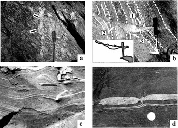
Figure 20. (a) A subvertical quartz vein (cross-cutting element) cut across the gneissic foliations. The vein is top-to-left (up) ductile sheared. Greater Himalayan Crystallines, Bhagirathi section, India. Reproduced with permission from Mukherjee Reference Mukherjee2013d . Atlas of Shear Zone Structures in Meso-scale. Springer. ISBN 978-3-319-00089-3. (b) A leucosome vein (cross-cutting element) in migmatite cut across the migmatitic foliations. Greater Himalayan Crystallines, Sutlej section, India. (c) A deformed irregular-shaped quartz vein (cross-cutting element) cuts host-fabric elements of quartz. Top-to-right ductile sheared. Matches with an overturned fold left to the pen. Ambaji, Gujrat, India. Reproduced with permission from Mukherjee Reference Mukherjee2013d . Atlas of Shear Zone Structures in Meso-scale. Springer. ISBN 978-3-319-00089-3. (d) Inter-boudin space is filled by a secondary quartz vein. A sharp short normal fault affects the lozenge and a normal dragged quartz vein (bottom). Greater Himalayan Crystallines, Goriganga section, India. Reproduced with permission from Mukherjee Reference Mukherjee2013d . Atlas of Shear Zone Structures in Meso-scale. Springer. ISBN 978-3-319-00089-3. (a, b, d) Observed on subvertical planes; (c) observed on a subhorizontal plane.
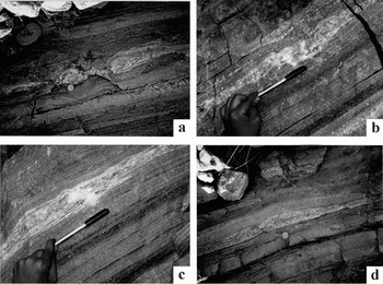
Figure 21. All observations on subvertical planes. (a) Lenticular boudin of calc-silicate layer within mylonitized gneiss/migmatite host rock. Length of photograph: 30 cm. Reproduced with permission from Mukherjee Reference Mukherjee2013d . Atlas of Shear Zone Structures in Meso-scale. Springer. ISBN 978-3-319-00089-3. (b, c) Boudinaged calc-silicate layer with polygonal secondary quartz at inter-boudin space. A second minor pinch is present above the folded fingers. Reproduced with permission from Mukherjee Reference Mukherjee2013d . Atlas of Shear Zone Structures in Meso-scale. Springer. ISBN 978-3-319-00089-3. (d) Listric normal faulted calc-silicate layer within mylonitized gneiss/migmatite. (a–d) Karcham, Sutlej section of Greater Himalayan Crystallines, Himachal Pradesh, India. Reproduced with permission from Mukherjee Reference Mukherjee2013d . Atlas of Shear Zone Structures in Meso-scale. Springer. ISBN 978-3-319-00089-3.
The mylonitic foliations acting as HE penetrates the CE (two arrows on Fig. 20a); this is therefore subtype 1.1.1 of Figure 18. Irregular non-linear geometry of the CE can be defined by leucosome pods inside migmatites (Fig. 20b). The CE may sharply truncate some of the HE migmatitic foliation planes defined by leucosomes and melanosomes. This is equivalent to subtype 1.1.2 of Figure 18. At other parts however, leucosome HEs joined with the CE resemble a feeder relationship (full arrow 1 in Fig. 20b). The senses of drag along the same side of the CE differ (compare those at arrows 2 and 3 in Fig. 20b). This is a natural example of subtype a.ii in Figure 19. Where leucosomes cut across migmatitic foliations in migmatites, a marker foliation plane is sometimes difficult to decipher. Although a slip is understood, its sense and magnitude remains indeterminate. The classification scheme in Figure 19 is therefore difficult to apply in this case.
A clear convex/concave sense of curvature does not develop in all mesoscopic FS (Fig. 20c). A cross-cutting element as a discrete plane rather than a zone of rocks or minerals is demonstrated in Figure 20d. Here the inter-boudin mineral is normal faulted (a-type FS of Passchier, Reference Passchier2001); this is type 1.2 of Figure 18. Further, opposite senses of (normal) drag across the fault plane and a clear-cut slip developed in a layer of quartz below the boudin is an example of subtype b.1.2.1 of Figure 19. Boudinaged calc-silicate layers (Fig. 21a–c) with secondary quartz of various shapes in the inter-boudin space acted as the CE, defining type 1.1 of Figure 18. Shear fracture boudins (Fig. 21d) with no minerals developed along the fault plane are classified as type 1.2 of Figure 18. The internal foliation planes of these boudins are not dragged; this FS is therefore subtype b.2 of Figure 19.
Since the HE markers are either not easily decipherable in these boudins or non-systematic (Figs 20d, 21a–d), Passchier's (Reference Passchier2001) classification of boudins (Fig. 13) is difficult to apply to them. For the same reason, unlike Goscombe, Passchier & Hand (Reference Goscombe, Passchier and Hand2004; Fig. 14), it is difficult to judge whether HE in most of these boudins (Figs 20b, 21a–c) indicate a normal or a reverse drag. A lozenge-type inter-boudin quartz vein (Fig. 20d) is similar to that of figure 4a of Arslan, Passchier & Koehn (Reference Arslan, Passchier and Koehn2008), and a polygonal quartz pod in the inter-boudin space (Fig. 21a) matches the X-type of figure 4c of Arslan, Passchier & Koehn (Reference Arslan, Passchier and Koehn2008).
6. Conclusions
Flanking structures (FS) are deflections of planar and linear host-fabric elements (HE) adjacent to the cross-cutting elements (CE) found in many sheared rocks. The concept also includes rotating CE and any associated drag folds in their footwalls. In natural examples, the HE may be thicker near the CE. Several morphological parameters were defined and FS classified (Coelho, Passchier & Grasemann, Reference Coelho, Passchier and Grasemann2005; Passchier & Trouw, Reference Passchier and Trouw2005; Mulchrone, Reference Mulchrone2007; Maeder, Passchier & Koehn, Reference Maeder, Passchier and Koehn2009; Mukherjee & Koyi, Reference Mukherjee and Koyi2009). This review adds two new FS classification schemes by considering all possible cases of drag and slip of the HE. Neither the HE geometry near the CE nor the asymmetric CEs represent the bulk shear sense. Several single FS types which are mirror images of each other are also unsuitable for deducing the shear sense. However, conjugate FS give reliable shear direction (Fig. 11). In microscopic examples, parallelogram- and sigmoid-shaped inclusions of one mineral within another represent the correct shear sense. The CEs might develop before, during or after the bulk shear event. Except for the former case, heterogeneous deformation fields perturb around CEs even during a homogeneous strain. Only the CEs of normal shear bands are assumed to attain sigmoid shape; such CEs resemble a kind of mineral ‘fish’ (ten Grotenhuis, Trouw & Passchier, Reference ten Grotenhuis, Trouw and Passchier2003; Mukherjee, Reference Mukherjee2011b ). With progressive shear, a-type FS may evolve into an s-type. Still-higher strains might develop intrafolial or sheath folds where the CE and the HE are too closely spaced to be distinguished (Fig. 10).
Analogue models with two CEs were simulated to give five regional deformation scenarios. The presence of secondary shear planes indicates general/sub-simple shear. The study of several FS from rocks constrains its kinematics. Unlike (1) rigidity, (2) friction between the HE and the CE, (3) thickness and rheology of the CE and (4) any pre-existing structures of the HE, the style of drag is governed by only two factors: (1) the angular relation between the HE and the CE before shear; and (2) the relative magnitudes of throw and vertical separation resulting from slip of the HE. Note that the angle mentioned in the former point is different from tilt. A too-rigid CE generates an n-type FS (drag, no slip). Pure sheared cavities that act as passive markers within foliated rocks and highly sheared foliation boudins create reverse drags. The shape of drag folds around boudinaged clasts depends on the shape of those clasts. Boudinage may propagate along one of the directions of simple shear.
Strongly foliated rocks are not necessarily anisotropic (Kocher & Mancktelow, Reference Kocher and Mancktelow2006). As a result, how well foliated the rock is cannot be used to predict the dominant kind of FS. All the models of FS describe their developments in ductile shear zones of Newtonian and non-Newtonian rheologies bound by parallel boundaries. The concept of FS can be furthered on shear zones with non-parallel boundaries (e.g. Mandal, Samanta & Chakraborty, Reference Mandal, Samanta and Chakraborty2002).
Acknowledgements
The support of the Department of Science and Technology (India) Fast Track project number SR/FTP/ES-117/2009 is acknowledged. Meticulous reviews by John Cosgrove, Arzu Arslan and an anonymous reviewer are greatly appreciated. Chris Talbot is thanked for thoroughly improving English. Thanks are extended to Mark Allen and Susie Bloor for editorial handling and Elaine Rowan for copy-editing.


