NOMENCLATURE
- AR
wing aspect ratio
 $C_{D_0}$
zero-lift drag coefficient
- e
Oswald efficiency factor
- E
energy (J)
- E spec
battery mass specific energy (J/N)
- L/D
lift to drag ratio
- MF
subsystem mass fraction
- n
load factor
- n u
ultimate load factor (generally 50% higher than the limit load)
- N
number of aircraft joined side-by-side
- P
power (W)
- R j
air range of cruise segments in joined configuration (m)
- R tot
total aircraft air range (m)
- S
wing reference area (m2)
- t
flight time (s)
- V
airspeed (m/s)
- W 0
aircraft gross weight (N)
- W
component weight (N)

Greek Symbol
- η p
propulsive system efficiency
- ρ
air density (kg/m3)
- ρ m
structural material density (kg/m3)
- σ max
maximum tensile stress for yield or buckling (Pa)
1.0 INTRODUCTION
The rapid development of unmanned system enabling technologies has led to an increased interest in the use of unmanned aerial vehicles (UAVs) for a diverse set of missions over the past two decades. Utilising several small, sensor equipped, UAVs working cooperatively as a swarm has further been found to allow for an efficient and relatively low cost solution to the closer monitoring of large land or sea areas, making such systems particularly suitable for search and rescue or wide-area monitoring missions(Reference Vincent and Rubin1).
The range and endurance of small UAVs is however still limited by the electrical energy density of current generation batteries. Furthermore, if access to remote areas is required, the energy requirement for the transit segment to and from the target area can severely reduce the UAV’s time on station. One possible method by which the energy consumption during the cruise segments of the mission profile could be reduced, as several aircraft would be expected to transit to the target location concurrently, is flying several aircraft in formation. Experimental studies of three aircraft models flying in a V-formation at Reynolds numbers of 3.5 × 10⁵ have shown a maximum possible increase in lift-to-drag ratio (L/D) of 24% for the system, corresponding to an analogous increase in cruise range for the aircraft(Reference Korkischko and Konrath2). Concentrating on larger aircraft and attempting to address the hazards of close formation flight, Ning et al(Reference Ning, Flanzer and Kroo3) investigated the savings possible from extended formation flying of airliners, finding that a two or three aircraft formation, spaced up to 40 spans apart, could theoretically result in induced drag reductions as high as 30 and 40% respectively. As the parasitic drag component remains constant, for typical cruising conditions this corresponds to a maximum possible increase in L/D of approximately 15–20%. This is in line with the maximum levels of thrust reduction quoted for flight tests of a two aircraft formation conducted by NASA using C-17 cargo transports, however due to imperfect tracking of the trailing vortices, the maximum average drag reduction observed over a three-minute period was found to be closer to 7–8%(Reference Pahle, Berger, Venti, Faber, James, Duggan and Cardinal4).
An alternative method by which the aerodynamic efficiency of several aircraft, flying to the same target area, could be even further increased is by joining multiple aircraft side-by-side for the cruise segments, as seen in Fig. 1. Joining multiple wing sections tip-to-tip, the resulting joined aircraft’s span b, wing area S, and therefore the wing aspect ratio, AR = b 2/S, are increased, therefore offering a reduction in induced drag for all constituent aircraft while joined. The potential benefits in energy consumption for an aircraft of gross weight W 0 can be seen by considering the energy required, E, for an aircraft to travel a distance R in steady level flight, given by Gundlach(Reference Gundlach5) as
 \begin{equation}E= \frac{W_0 R}{\eta_p (L/D)},\end{equation}
where η p is the total propulsive system efficiency, estimated as the product of all propulsive system component efficiencies. Assuming a parabolic drag polar for the aircraft, the maximum lift-to-drag ratio, (L/D)max, of a single aircraft is attained at the minimum drag speed, V mD, which are given by Raymer(Reference Raymer6) to be
 \begin{equation}(L/D)_{{\rm max},1} = \frac{1}{2} \sqrt{\frac{\pi \, AR \, e}{C_{D_0}}},\end{equation}
 \begin{equation}V_{mD} = \sqrt{\frac{2 W_0}{\rho S}} \sqrt[4]{\frac{1}{C_{D_0}\pi \, AR \, e}}.\end{equation}
Consequently, when N aircraft are joined in flight, the aspect ratio would increase by a factor of N and the minimum energy required per aircraft when joined would become
 \begin{equation} (E_j)_{\rm min}= \frac{2 W_0 R}{\eta_p} \sqrt{\frac{C_{D_0}}{\pi N \,AR\,e}} = \frac{(E_s)_{\rm min}}{\sqrt{N}},\end{equation}
showing that joining two aircraft in flight could reduce the cruise segment energy requirement by 29.3%, while with three aircraft a reduction of 42.2% would be possible, double that expected from close or extended formation flying. Any further increase in N would further reduce the total energy requirement but at a diminishing rate (following  $1/\sqrt{N}$). It should be noted however that increasing the joined platform’s combined wing aspect ratio would reduce the system’s optimum cruise speed, and therefore time to station, by a factor of
  $\sqrt[4]{N}$ following Equation (3), while maintaining the same cruise airspeed would result in lower energy savings. Furthermore the use of tip-to-tip joining does not preclude multiple sets of joined aircraft from flying in close or extended formation to achieve even greater reductions in induced drag.

Figure 1. Sample mission profile, featuring joined cruise and individual loiter segments.
The idea of joining aircraft in flight is not novel. In the early 1950s project ‘‘Tip-Tow’’ investigated the in-flight joining of a B-29A bomber with two F-86D fighters in order to extend the latter’s range, with a minimal range impact on the carrier aircraft’s range(Reference Anderson7). The project was deemed successful, showing that aircraft could successfully be joined in flight and confirming the projected increase in parasitic aircraft range and overall reduction in induced drag, despite the weight penalties associated with the addition of a coupling mechanism. Further investigations however highlighted issues in the areas of stability and control for the joined configuration where hinged connections where used and the project was terminated. NASA’s Trans-Oceanic Air-Train concept(Reference Yaros, Sexstone, Huebner, Lamar, McKinley, Torres, Burley, Scott and Small8) involved the joining of several high aspect ratio, untapered wing sections carrying containerised cargo, with a central control vehicle, to form an extremely high aspect ratio, swept wing aircraft capable of outstanding aerodynamic performance at moderate Mach numbers. The aerodynamic advantages of joined flight are also the driving force behind BAE Systems’ ‘‘Transformer’’ concept, where a rhomboid and two delta wing, jet powered UAVs join in flight to increase their combined wings’ aspect ratio and therefore their range. Paterson et al(Reference Patterson, Quinlan, Fredericks, Tse and Bakhle9) further consider the joining of a parent aircraft to multiple, smaller, wing-shaped, VTOL delivery drones to enable the efficient, distributed, delivery of cargo over long ranges.
While the majority of past studies involved the joining of parasitic, less efficient aircraft, to a larger mothership, such that the overall system efficiency increases, some concepts have proposed the joining of identical aircraft. Aurora Flight Sciences’ submission for DARPA’s VULTURE program, called ‘‘Odysseus’’, considered the rigid, tip-to-tip joining of three identical solar-powered aircraft in a Z-configuration, so as to maximise solar energy collection and allow swapping of aircraft so the platform could remain on station indefinitely(Reference Trimble10). Furthermore, the potential benefits of joining identical aircraft in both a side-by-side and/or a fore-aft configuration, to generate what they term as a meta-aircraft, are also identified by Montalvo and Costello(Reference Montalvo and Costello11), who further investigated the dynamics of the system, characterising the dynamic modes of the resulting meta aircraft and their dependence on the meta aircraft’s configuration.
Considering the literature available, discussions tend to concentrate almost exclusively on the aerodynamic benefits, or the implications of joining on stability and control. The requirement for a joining mechanism to be added and its associated weight, as well as the potential effects of joined flight on the wing structural loads and therefore its structural weight, is however largely ignored. These changes to the aircraft gross weight could lead to a commensurate increase in the platform’s energy requirement for all mission segments, as shown in Equation (1). Montalvo indicates that a reduction in structural weight might be possible due to improved span loading of the wings and a reduction in bending moments, in line with the findings of past multibody aircraft designs studies(Reference Montalvo and Costello11). This assessment however ignores the increase in the overall weight of the combined system and the significant increase in root bending moments that will be experienced along the combined system’s centreline at limit loading conditions (n > 1), where the load factor n is the ratio of the maximum aerodynamic loading to vehicle gross weight. This is particularly applicable in cases where rigid or semi-rigid connections are used in order to avoid the stability and control issues associated with hinged joints between wing sections, which would likely reduce the magnitude of root bending moments experience but would allow for flapping degrees of freedom, as identified in past studies(Reference Montalvo and Costello11,Reference Leylek and Costello12) .
The objective of this work is therefore to investigate the viability of joining a number of identical UAVs side-by-side and to quantify the relative impact of joining on the aerodynamic efficiency and structural weight of an aircraft when designed for joined operation. The effect that major aircraft design characteristics, mission parameters, the type of joining mechanism used and the number of aircraft being joined will be further investigated, first by determining their effect on the battery and structural mass through an analytical parametric study, followed by the full design of sample aircraft to further quantify the effect of joining on the various aircraft systems and investigate the impact of different joining mechanism design choices.
While the primary benefit of joined flight is the extension of a UAV’s range, or time on station (for a constant range), in this study the design mission profile is kept constant and the effect of designing aircraft for joined flight on the aircraft total weight and energy requirement to complete the mission is investigated. Nevertheless, the methods presented in this paper can be easily reordered to investigate the range extension possible at a constant weight or energy requirement.
2.0 PARAMETRIC ANALYSIS
In order to estimate the impact of joined flight on the battery, structural, and gross weight of the aircraft, and identify the key design parameters and their level of influence on the viability of joined flight, an analytic parametric study can be carried out. A flying wing configuration is considered for its simplicity and ability to best represent the tradeoffs between aerodynamics and structural weight alone, however the weight of a fuselage can be easily added to the model. The aircraft gross weight, W 0, can be expressed as
 \begin{equation}W_0 = \frac{W_{\rm payload}+W_{av}}{1-MF_{\rm bat}-MF_{\rm str}-MF_{\rm prop}-MF_{j}}\end{equation}
where W payload is payload weight, W av the avionics weight. The weight of the batteries, structure, propulsive system and joining system are expressed as the mass fractions MF bat, MF str, MF prop and MF j respectively. The joining mechanism mass fraction accounts for the mass of any structural and sensing components necessary to enable the secure connection of two or more vehicles in flight and is dependent on the type of mechanism used and the loads it is subjected to. Based on Equation (1) the battery mass fraction, defined as the ratio of the battery weight to the gross aircraft weight, for a cruise segment can be expressed as
 \begin{equation}MF_{\rm bat,cr} = \frac{E}{E_{\rm spec} W_0} = \frac{R}{\eta_p E_{\rm spec} (L/D)},\end{equation}
where E spec is the battery specific energy in J/N. The effect of joining N aircraft can be better observed by expressing the system’s L/D for a cruise segment flown at an airspeed V in terms of the single aircraft’s (L/D)max, given by Equation (2), as
 \begin{equation}MF_{{\rm bat,cr},N} = \frac{R}{2 \eta_p E_{\rm spec} (L/D)_{{\rm max},1}} \left( \overline{V}^2 + \frac{1}{N \overline{V}^2} \right),\end{equation}
where the non-dimensional flight speed  $\overline{V}=V/V_{mD,1}$ and V mD,1 is the aircraft minimum drag speed when N = 1, given by Equation (3).
The structural mass fraction of a flying wing aircraft can be analytically approximated by considering the material thickness necessary to avoid structural failure at an ultimate load factor n u, given a maximum allowable yield or buckling stress σ max. Following the derivation provided in the Appendix,
 \begin{equation}MF_{{\rm str},N} = \frac{\rho_m g C_2 N^2 n_u}{6 \pi (t/c) C_1 \sigma_{\rm max}} \sqrt{\frac{W_0 AR^3}{W_0/S}},\end{equation}
where ρ m is the material density and t/c is the wing’s thickness to chord ratio. The propulsive system’s mass fraction, MF prop is determined by the maximum engine power output requirement, typically set by climb, ceiling, or manoeuvring constraints, and can thus be assumed to be constant at this stage.
Assuming that the battery and material properties are constant, the major design parameters identified are the aircraft wing loading W 0/S, wing aspect ratio, the proportion of the total distance flown where the aircraft were joined (R j/R tot) and the mass fraction of the joining mechanism.
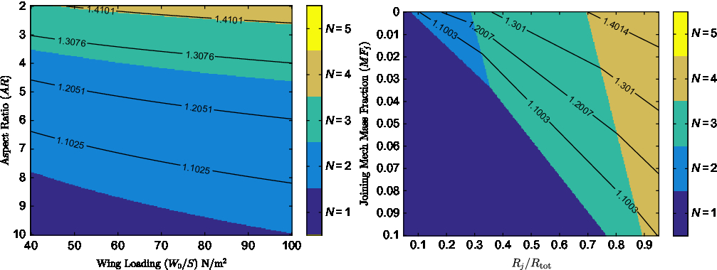
Figure 2 shows the effect of wing loading and aspect ratio on the minimum gross weight possible for a UAV operating as part of a swarm. Each vehicle is designed to carry a payload of 0.25kg, representative of the payload of a small surveillance UAV, capable of a total air range R tot = 100km and spending 40% of that in a joined configuration (R j/R tot = 0.4). For Fig. 2, no weight penalty associated with the addition of a joining mechanism is assumed (MF j = 0), in order for the tradeoff between aerodynamic benefits and structural penalties to be investigated alone.
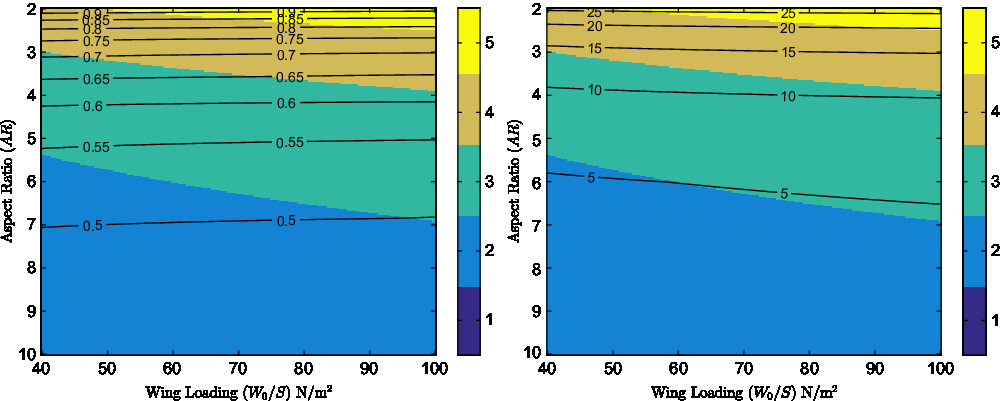
Figure 2. Contours of minimum vehicle gross weight in kg (left) and percentage gross weight reduction (right), with background colour indicating the number of UAVs for which the minimum is achieved, for R j/R tot = 0.4 and MF j = 0.
For the battery specific energy and material specific strength (σ max/ρ m) used, the plots show that a reduction in gross weight is possible for all cases where joining is used, assuming a massless joining mechanism. The plots indicate that an increase in wing aspect ratio will result in a reduction of the minimum aircraft mass possible, however the magnitude of percentage gross weight savings possible and the number of UAVs that must be joined to achieve them are diminished. For example at a wing loading of 70N/m2, using a wing aspect ratio of 7, the minimum gross weight of a vehicle capable of completing the mission specified above will be 0.5kg and will be achieved when 2 UAVs join. This can be further seen to represent a 4.2% reduction in gross weight compared to that of a UAV completing this mission by itself. Reducing the aspect ratio to 3 indicates that a minimum gross weight of 0.7kg would be possible when N = 4, representing a 14.8% reduction in gross weight relative to the mass of a UAV completing the mission alone. This behaviour is exhibited as at higher aspect ratios, the structural weight penalty is significantly higher than the energy savings associated with the reduction in induced drag. Figure 2 further shows that for an aircraft travelling at its best cruise speed, an increase of wing loading will result in a reduction of the overall aircraft gross weight but, as wing loading only affects the structural mass fraction, savings can be modest if materials with high specific strengths are used. A more significant effect of increasing wing loading appears to be the increase in the number of UAVs that could be joined at a given aspect ratio to achieve higher savings. It should be noted that, given the cumulative effect of the reduction in aircraft mass and the battery mass fraction, the study found that even in cases of moderate increases in mass, the electric energy required to complete the mission was decreased.
Choosing an aspect ratio of 3.5 and wing loading of 75N/m2 to investigate further, as significant savings can be seen for this case, Fig. 3 shows how the joining mechanism’s mass fraction and the proportion of flight time spent in a joined configuration (R j/R tot affect the level of reduction in gross weight possible. The plots indicate that increasing the amount of time spent in joined rather than individual flight will result in a reduction in aircraft gross weight and energy required. Furthermore as the proportion of the flight distance spent in a joined configuration is increased, the number of aircraft that must be joined to achieve the maximum level of savings possible increases, albeit at a diminishing rate, again reflecting the impact of joined flight on the battery and structural mass fractions.
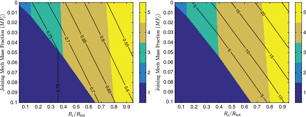
Figure 3. Contours of minimum gross weight in kg (left) and percentage gross weight reduction (right), with background colour indicating the number of UAVs for which the minimum is achieved, for AR = 3.5 and W 0/S = 75N/m2.
Figure 3 illustrates that the level of savings possible is inversely proportional to the mass fraction of the joining mechanism, further indicating that for each set of design parameters there will be a minimum joined cruise range, greatly dependent of the joining mechanism’s mass fraction, below which achieving mass savings will be impossible. Unlike the effect of the previously discussed parameters however, the joining mechanism mass fraction appears to have a relatively minor effect on the number of aircraft that should be joined for maximum savings to be achieved.
The potential impact that joining flight can have on an aircraft’s range, if the gross weight is to be kept constant, can be extracted by combining Equations (5) and (7) and assuming the propulsion system mass fraction remains constant. The ratio of increase in range possible (R j) when operating in a joined configuration, as a fraction of the range possible if the aircraft was flying the entire mission alone (R s), is given by
 \begin{equation}\frac{R_j}{R_s} = \frac{N \overline{V}^4 + N}{N \overline{V}^4 + 1} \left( 1 + \frac{MF_{\text{str},1}(n_{u,1}-n_{u,N} N^2)-MF_{j}}{MF_{\text{bat},cr},1} \right)\,\end{equation}
where MF bat,cr,1 is the battery mass fraction required by a solo aircraft to complete a cruise segment of range R s. Figure 4 shows the effect of the previously discussed parameters on the the joined segment range possible for a constant mass. Comparing these plots to Figs 2 and 3, one can see that the effects of the design parameters investigated are consistent, indicating range extensions up to 40%, however the area over which an extension in range is found to be possible is narrower than that for which reductions in mass were identified. Similarly the number of aircraft that resulted in the maximum extension in cruise range was often lower than that for which maximum mass reductions were achieved. This can be traced back to the effect that aircraft mass has on the structural mass fraction, whereby, based on Equation (8), a reduction in gross weight results in an reduction of the structural mass fraction penalty resulting from joined flight.

Equation (9) further indicates what the effect of parameters previously treated as constant might be on the level of range extension possible. If the original single aircraft was designed for operation at a lower speed, whereby  $\overline{V} \lt 1$ and lift induced drag is dominant, significantly higher range extension is achieved. Similarly, much greater benefits can be achievable when redesigning aircraft designed for long range flights or featuring low specific energy batteries, as both would affect the original aircraft’s battery mass fraction. Finally an increase in material specific strength reduces the structural mass fraction, leading to higher range extensions being realised.
Based on these parametric study results, the use of joined flight seems most appropriate for aircraft that must feature low aspect ratio wings and, while increasing the wing loading can result in a reduction of structural mass, the choice of wing loading should be driven primarily by achieving aerodynamic rather than structural weight benefits. It should be noted that the above results have assumed a constant propulsion system mass fraction and have not considered any manufacturing constraints for the aircraft structure, both suggesting that the predicted savings relative to the single aircraft might be somewhat underestimated. Furthermore, based on the significant impact that the joining mechanism mass fraction was shown to have on the level of weight savings or range extension possible in Figs 3 and 4, the viability of joined flight cannot be determined without quantifying the magnitude of the joining mechanism mass fraction. To this end a full conceptual design of a UAV designed for joined flight, the methodology for which is presented in the following sections, was carried out.
3.0 DESIGN OVERVIEW
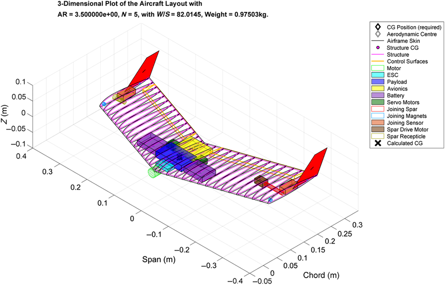
In order for the vehicle to be sized using more advanced methods than those presented in the parametric analysis, its baseline configuration and performance constraints must be first defined. As with the parametric study, in order for this study to concentrate primarily on the trade-off between the aerodynamic advantages and structural implications of joined flight, a swept, flying-wing configuration was selected. Figure 5 shows an outline of the vehicle, with all systems being placed within the aircraft’s structural volume. The internal volume was found to be sufficient in the majority of studies, primarily due to the relatively low-wing loadings imposed by the maximum stall velocity constraint stemming from the desire to hand or catapult launch the UAV. A constant chord wing section was used, as use of taper was found to significantly increase the structural weight penalty due to the tip-to-tip joining.

Figure 5. Sample UAV illustrating the layout of a UAV designed for joined flight with a deployable spar joint.
The aircraft was designed to be statically stable in pitch with a static margin of 5% of the mean aerodynamic chord. To achieve the desired static margin, while limiting the amount of sweep utilised, a tractor configuration was selected, moving the heavier components of the propulsion system forward. Aft of the propulsion system, the UAV’s payload and avionics weighing approximately 70g are placed along the aircraft centreline. For these studies, a payload of 250g is assumed as in the parametric studies. Battery packs sized to power the propulsive and avionics systems for the duration of the mission are placed just outboard, typically towards the wing leading edge to maintain a forward centre of gravity position. Actuators, sensors and structural components required for joining in flight are placed in of near the aircraft’s wingtips. The aircraft is controlled in pitch and roll by a set of elevons, occupying 25% of the local chord, over the majority of the aircraft’s trailing edge. Yaw control has not been considered but tip fins are utilised to ensure directional stability for the aircraft. The tip fins feature a flat bottomed, half airfoil shape to ensure minimum drag rise when UAVs are in the joined configuration.
The design mission profile of the aircraft can be seen in Fig. 1. The aircraft are assumed to be launched and climb to their cruise altitude individually, where a 5-minute solo loiter is assumed to account for the time taken for the aircraft to join together. The desired mean rate of climb is defined by the cruise altitude and desired time to climb. Cruise segments to and from the target area are assumed to take place in a side-by-side joined configuration. A baseline mission radius of 10km and time to target of 10 minutes are used for this analysis. At the target area, the aircraft are assumed to be capable of detaching instantaneously and loiter at their best endurance speed for 45 minutes. The aircraft return to the launch site in a joined configuration and operating conditions identical to the outbound journey. The descent to land and recovery of the UAVs, following their separation in flight, are assumed to be instantaneous and therefore not consume any power.
4.0 METHODOLOGY
The aircraft is sized for the design mission profile using a custom conceptual design framework, implemented in MATLAB. Figure 6 illustrates the main elements of the sizing framework and the general order in which components are sized and analyses take place. An iterative approach is utilised, with each module updating the aircraft design and/or performance metrics, until the aircraft gross weight converges. Subsequent parts of this section describe the methodologies used in each module in more detail.
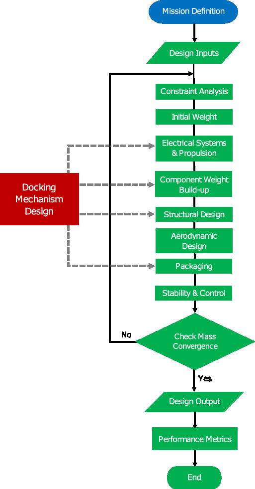
Figure 6. Flowchart of the design framework used.
4.1 Initial sizing
The initial sizing module calculates the aircraft gross weight W 0, wing loading W 0/S and power loading P/W 0 subject to the performance constraints set in the design mission profile and the aircraft aerodynamic, propulsive and mass properties. These properties are initially assumed or guesstimated based on comparable UAV designs and updated by the relevant analysis module in subsequent iterations.
In order for the aircraft to be capable of completing the predefined mission profile, it must be capable of generating sufficient thrust to maintain steady flight. Considering the specific excess power required to complete the ith flight segment is given by(Reference Raymer6) as
 \begin{equation}\left(\frac{dh}{dt}\right)_i = \eta_p \frac{P_i}{W_0} -\frac{V_i D_i}{W_0},\end{equation}
where D i is the total drag force the system is subjected to at an airspeed V i and (dh/dt)i is the rate of climb required; the power required, P i, can be estimated as
 \begin{equation}\frac{P_i}{W_0} = \frac{1}{{\eta_p}_i} \left[\left(\frac{dh}{dt}\right)_i +\frac{\rho_i V_i^3 C_{D_0}}{2 W_0/S} + \frac{2 n_i^2 W_0/S}{\rho_i {V_i} \pi N_i AR e_i} \right],\end{equation}
maintaining the assumption of a parabolic drag polar, and where N i is the number of UAVs operating in a joined configuration and n i is the manoeuvre load factor required for the ith flight segment. Knowing the power requirements for each stage of flight, the propulsive system must be sized to meet the highest among them.
By considering the calculated weights of each individual aircraft component, rather than their more crudely estimated mass fractions, the aircraft gross weight can be calculated by rearranging (5) as
 \begin{equation}W_0 = \frac{W_{\rm str} + W_{\rm prop} + W_{\rm av} + W_{j} + W_{\rm payload}}{1-\sum_i MF_i}\end{equation}
where W str is the aircraft structural structural weight, W prop the propulsion system weight excluding the batteries, W av the avionics system weight, W j the joining mechanism weight, calculated for the specific type of joining mechanism and the loads it must be designed for, and W payload the payload weight. As the structural and propulsive system weights are dependent on the aircraft’s gross weight and aerodynamic properties, the values computed in the previous iteration are used. Following (6), the general expression for estimating the battery mass fraction, MF i, required to complete the ith mission segment is
 \begin{equation}MF_i = \frac{t_i}{f_{\rm usable} E_{\rm spec}}\left(\frac{P_i}{W_0} + \frac{P_{av}}{W_0}\right)\,\end{equation}
where t i is the time (in seconds) required to complete the ith mission segment, f usable is the useful battery capacity fraction, accounting for the loss of battery capacity at the battery’s end of life, and P av is the average power required to power the avionics system and any joining apparatus.
From (11) and (13) it is clear that the the aircraft power to weight ratio and battery mass fraction are significantly affected by the aircraft wing loading. Additionally, the wing loading chosen will affect the wing structural weight by altering both the wing structural volume and the joined wing span. It is therefore treated as a constrained optimisation parameter, its maximum value being defined by internal volume requirements for systems packaging and by the desired stall speed, which in turn is defined by the speed achievable by a catapult or hand launch.
4.2 Propulsive system
The propulsive system analysis module is responsible for predicting the propulsive system weight, efficiency and dimensions, such that the power output requirements given by (11) are met. Given the relatively large mass fraction of the propulsive system for electrically powered UAVs, the accuracy of the system weight and efficiency predictions is increasingly important if the knock-on effects of aerodynamic efficiency and structural weight increases due to designing for joined flight are to be accurately quantified.
To achieve this increase level of detail the weight and efficiency of the propeller, motor and electronic speed controller (ESC) are sized so that they can co-operate optimally. The method presented below is similar to that employed by Gur and Rosen(Reference Gur and Rosen13) and Bershadsky et al(Reference Bershadsky, Haviland and Johnson14), however the parametric descriptions of components were updated to reflect the characteristics of components currently available. Direct current (DC) motors were chosen for their high power to weight ratio and efficiency. Motor weight was estimated using the empirical model developed by Dutton(Reference Dutton15), where the motor power output, and motor K V rating, a parameter defining the motor unloaded rotational speed (Ω) to voltage ratio, were found to be the main determining parameters. A similar empirical relation was generated for ESCs, small electronic devices controlling the motor rotational speed, following a review of devices available in the hobby market that indicated a strong relation between their weight and their rated voltage and current.
The propulsion system is designed around a user specified propeller whose efficiency (η prop) variation with advance ratio is known, for example from the test data as those provided by Brandt and Selig(Reference Brandt and Selig16). The motor is subsequently sized to maximise overall propulsive efficiency during cruise, typically representing the longest flight segment. To accurately predict the motor efficiency at different flight stages and therefore the energy required as discussed in Section 4.1, a simplified motor efficiency model, derived from that presented by Gur and Rosen(Reference Gur and Rosen13), was utilised whereby the total propulsive system efficiency at each flight segment is
 \begin{equation}{{\eta_p}_i} =\eta_{\rm ESC} \eta_{\rm prop} \left(1-\frac{I_0}{I_m}\right) \frac{\Omega}{\Omega + I_m R_a K_V }.\end{equation}
The motor running current I m is given as a function of the motor shaft power required for each flight segment P i, calculated using Equation (11), and
 \begin{equation}I_m = \frac{{\eta_p}_i}{\eta_{\rm prop}} \, P_i \frac{K_V}{\Omega} + I_0.\end{equation}
The motor internal resistance, R a, and zero-load current, I 0, are modelled empirically as functions of the motor size and therefore maximum power output. In the absence of bench test or manufacturers’ data on the efficiency of ESC devices, a value of η ESC = 0.97 was used, as per Bershadsky et al(Reference Bershadsky, Haviland and Johnson14).
4.3 Structural sizing
The structural sizing module uses the aerodynamic loads and system weights provided by the relevant subroutines to estimate the UAV’s structural weight and inertial properties.The structural weight fraction of UAVs is greatly dependent on the aircraft W 0 and the type of structural layout used. Unlike larger aircraft, where semi-monocoque construction is the norm, UAV wing structures are often designed with weight, manufacturability or cost as the primary design drivers, resulting in layouts ranging from rigid foam wings reinforced with spars or a rigid skin, hollow monocoque wing boxes, to truss based designs covered with unstressed skin. For the purposes of these studies a monocoque structure was assumed, featuring CFRP-foam sandwich skin panels, as it maximised the internal volume available for system placement, a key consideration for a flying wing vehicle, and was easily scalable. The skin panels were sized such that they could withstand the shear, bending and torsional loads applied under ultimate loading conditions at each stage of flight. It should be noted that as this study applies primarily to small UAVs, their unmanned nature and low mass make sizing for possible impact damage during the joining stage less constraining and therefore not considered in the sizing method presented.
Unlike the sizing of conventional aircraft, the limit loading experienced by an aircraft in joined flight is not necessarily symmetric and is dependent on the number of aircraft joined side-by-side, the location of the aircraft in the formation and the type of joining mechanism utilised. For example if five aircraft are joined side-by-side, the maximum bending moment will most likely be experienced at the root of the central aircraft in the formation. However, if one aircraft detaches, for an even number of aircraft in formation, the maximum bending moment will be experienced by the aircraft’s wingtip. Additionally, while the aircraft might be required to perform high load factor manoeuvres when flying individually, designing for high load factors is unnecessary during the cruise segment. Consequently the ultimate loading for the aircraft in both the solo and joined configuration must be considered.
Based on these considerations, the maximum shear force (F z) and bending (M y) and torsional (M x) moments likely to be experienced at each spanwise position 0 ≤ y′ ≤ b/2 is determined using
 \begin{equation}F_z(y'{}) = \int_{N b/2}^{y'{}} \left[n_u l(y) - w(y) \right] dy ;\end{equation}
 \begin{equation}M_y(y'{}) = \int_{N b/2}^{y'{}} \left[n_u l(y) - w(y) \right](y-y'{}) dy ;\end{equation}
 \begin{equation}M_x(y'{}) = \int_{N b/2}^{y'{}} \left\{ m_0(y) + n_u l(y) \left[x_{cs}(y'{}) - x_{ac}(y) \right] - w(y) \left[ x_{cs}(y'{}) - x_{cg}(y) \right] \right\} dy ,\end{equation}
where b is a single UAV’s wingspan, w(y) is the distributed aircraft self-weight, l(y) and m 0(y) are the sectional lift and zero-lift pitching moment distributions in level flight, n u is the ultimate load factor considered and x cs, x ac and x cg are the chordwise locations of the wing’s flexural axis, sectional aerodynamic centre and centre of gravity respectively. The number of carbon fibre laminae required to avoid yield, buckling and meet the prescribed tip deflection constraints is therefore found based on the maximum loading likely to be experienced. Given the size of the vehicles investigated, the number of laminae was assumed constant along the span, however for larger vehicles a varying number of laminae could result in structural weight savings. The foam core thickness is kept as an independent optimisation parameter, and was assumed to be 3–5mm for the purposes of the studies presented herein.
Based on the predefined wing planform and cross-sectional airfoil shape, and knowing the thickness and density of each structural layer required to counter the applied loads, the mass and inertial properties of the resulting structure are ultimately estimated.
4.4 Aerodynamics and stability
The aerodynamic analysis module is used to calculate the lifting and drag characteristics of the aircraft in both the solo and joined configurations. In order to minimise the design space to be investigated, the airfoil shape was kept constant in the design studies. A NACA 24112 was selected as the baseline airfoil, as its moderate thickness provided adequate internal volume and good stalling characteristics, while the reflexed camber profile minimised trim drag.
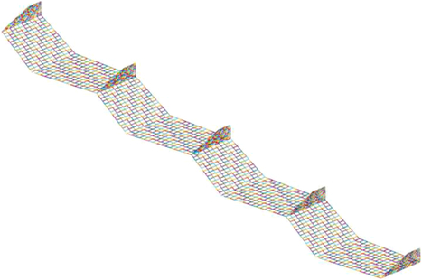
A lifting surface, potential flow solver, using the Vortex Lattice Method following the formulation given by Katz and Plotkin(Reference Katz and Plotkin17), is used as the basis for the majority of the aerodynamic computations. As seen in Fig. 7, the entire aircraft, including the vertical fins, is modelled providing estimates for the spanwise lift and moment distribution, wing lift curve slope, zero-lift angle of attack, zero-lift pitching moment, lift-induced drag factor and the longitudinal neutral point position. The zero-lift drag of the aircraft was assumed constant, irrespective of the number of UAVs joined side-by-side, and estimated using the component drag build-up method detailed by Raymer(Reference Raymer6).

Figure 7. VLM mesh for a sample UAV design for N = 4.
The aircraft is designed to be statically stable in pitch by ensuring an adequate static margin is achieved in all configurations, achieved by adjusting the position of the payload bay, battery packs and the wing sweep.The effect of elevator deflections on the aircraft’s lift, drag and pitching moment are determined based on empirical relations given by(18,19) . Trim analyses are carried out for each mission segment, calculating the elevator deflection necessary to achieve trim and the resulting levels of trim drag. These updated, trimmed drag coefficients are subsequently used to calculate aerodynamic drag and resize the propulsive system and battery packs.
4.5 Joining system
The joining system is responsible for ensuring that two vehicles can position themselves appropriately to enable joining, and can subsequently successfully join, remain joined and easily separate at the end of a joined flight segment. For this study the use of a lightweight ultrasonic distance measuring sensor, combined with the on-board GPS packaged in the avionics system was considered sufficient for positioning the aircraft. As Fig. 6 illustrates, the choice of joining mechanism architecture affects the sizing of the remaining aircraft’s subsystems in several ways. For example, the choice to use electromagnets to keep the aircraft joined in flight would not only affect the joining system weight but also increase electrical energy consumption during the cruise phase and therefore increase the size of battery required, as per Equation (13), leading to further knock on effects on the aircraft gross weight.
In addition to limiting the joining system weight and power consumption, the mechanism should be mechanically simple to increase reliability and assist in the joining process, such that a reduced level of precision in control is required to successfully join the aircraft, given the complex aerodynamics that might be experienced near the vehicles’ wingtips. Finally, the joining apparatus should have a minimal effect on the vehicle’s aerodynamic performance.
Another key choice revolves around the degrees of freedom allowed by the joining mechanism. As previously discussed, use of a hinged joint, such as that used in Project Tip-Tow, could potentially offer structural weight savings by reducing the magnitude of bending moments experienced by the aircraft in the middle of the joint configuration, however the flapping behaviour enabled by this joining mechanism could greatly affect the aircraft’s aeroelastic and flight mechanic responses. While the implementation of a more complex control system to alleviate such responses is possible, it is outside the scope of this study and therefore a simpler, rigid joint was implemented for all studies. Moreover, as they would result in significantly higher wing bending moments in the joined configurations, if designing aircraft with rigid joints proves to be viable, the use of hinged joints would likely result in even greater benefits. Based on the aforementioned considerations, two distinct types of rigid joining mechanisms, a deployable spar and a magnetic joint, were consequently investigated in this study and are described in detail in the following sections, along with the findings of the relevant design case studies.
5.0 CASE STUDIES
5.1 Deployable spar joint
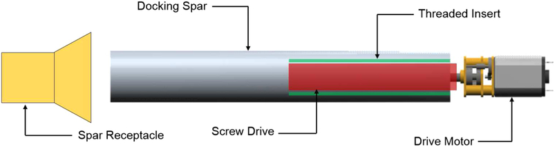
To meet all the requirements set out for the joining mechanism above, the deployable spar system seen in Fig. 8 was considered. The system is composed of a hollow carbon fibre spar, sized to transfer bending and shear loads, which can be deployed out of each aircraft’s port wing. The spar is extended into a receptacle located in each aircraft’s starboard wing using a small servo driving a screw mechanism. The receptacle is shaped as a conical draft tube, so as to correct small errors in positioning during the joining process. The weight of the spar is estimated based on the wall thickness required to avoid failure at ultimate loading conditions for the inboard-most joint. To minimise weight, the maximum diameter possible for the given wing thickness is utilised.

Figure 8. Illustration of deployable spar mechanism.
To further facilitate the joining process, a pair of rubber coated rare-earth magnets, of opposing polarity, are placed at each wingtip. The magnets are sized such that (i) they provide an axial force sufficient to counter the maximum bending moment expected at the joints in non-accelerating, level flight, (n = 1) and (ii) that they generate a static friction force capable of countering all torsional moments about the spar at the extremes of the aerodynamic loading envelope. The use of a rubber coating increases the surface frictional coefficient of each magnet, further reducing their size and therefore weight.
Figures 9 and 10 illustrate the effect of wing loading and aspect ratio, varied about the design point of 75N/m2 and AR = 3.5, a design point that the prior parametric study indicated would result in a significant reduction of gross weight. The vehicle gross weight, the energy required to complete the baseline mission and the battery, structural and joining mechanism mass fractions calculated are plotted.

Figure 9. Effect of wing loading (W/S) on aircraft mass breakdown and energy requirement for AR = 3.5 and N = 1–5 when using a deployable spar joint.

Figure 10. Effect of wing aspect ratio (AR) on aircraft mass breakdown and energy requirement for W/S = 75N/m2 and N = 1–5 when using a deployable spar joint.
In both cases, the joining of aircraft during the cruise segment results in a reduction of the battery mass fraction and the battery mass fraction is found to be inversely proportional to aspect ratio, as expected from Equation (4) and consistent the findings of the previously discussed parametric analysis. The wing loading on the other hand was found to have a significant effect not only on the battery mass fraction but also the magnitude by which joining reduced it. This can be attributed to the fact that, while the parametric analysis assumed the cruise speed to be equal to the minimum drag speed in each flight segment, maintaining a constant cruise speed will result in a reduction of  $\overline{V}$ as V mD is increased proportionally to wing loading. The level of savings is therefore greater as wing loading is increased and induced drag dominate, but the aircraft is operating in a speed-unstable condition. Departures from the behaviour described above, as in the case of N = 4 and N = 5 at low = wing loadings or high = aspect ratios, when significant increases in mass were observed, can be traced back to the presence of a constant energy requirement to power the avionics, whose battery mass fraction diminishes with increasing weight.
The effect of wing loading and aspect ratio on the structural mass fraction was also consistent with expectations, however the use of CFRP resulted in a discontinuous behaviour when additional plies had to be added. This can be seen in the cases of N = 4 and N = 5 where, when the wingspan and therefore bending moment become large enough, additional material is added to avoid buckling failures, increasing the structural mass fraction significantly. Furthermore, when excess strength is available for the minimum number of plies the structural mass fraction is found to be solely dependent on the wing surface area. Note that when the effects of aspect ratio on the battery and structural mass fractions are combined, a non-monotonic variation of vehicle gross weight and energy required is observed for N ≥ 4. This results from the structural mass fraction remaining constant between jumps in the number of CFRP laminae used while the battery mass fraction is a continuous function of aspect ratio. This behaviour was not captured in the prior parametric analysis, as the structural mass fraction derived is a continuous function of aspect ratio.
The deployable spar joint was found to have a significant mass fraction, ranging from 5% to 10% percent of W 0. As the major contributors to the weight of this group are sized based on the maximum shear force and bending moment experienced by a joint, it is reasonable that the joining mechanism mass fraction is proportional to the number of UAVs being joined and inversely proportional to the wingspan and therefore wing loading. It should be noted that MF j is also found to be inversely proportional to the wing aspect ratio, a behaviour traced back to the effect of aspect ratio on the aircraft weight, leading to an overall reduction in wingspan.
The combined impact of these effects can be seen in the plots of gross weight vs wing loading and aspect ratio. At an aspect ratio of 3.5 the use of joining did not result in a reduction in weight, and therefore a likely increase in maximum range, for wing loadings below 79N/m2. Above this level of wing loading, with no structural weight penalty due to joining and the added weight of the joining mechanism being equal to the battery weight saved, small reductions relative to the unmodified aircraft were observed. Even so however, the minimum weight for an aircraft designed for joined flight with AR = 3.5 was found to be 954g, 2.3% higher than the minimum of 933g for the unmodified aircraft. The studies conducted however did find that for aspect ratios below 2.5, the battery mass fraction required to complete the mission profile specified was such that the mission could only be completed if joining was used with N > = 4. It should be noted however that while a reduction in mass was only found to be possible at very low aspect ratios and high wing loadings, findings indicate that the total energy consumption of the system can be reduced over a much wider range of parameters.
The findings presented in Figs 9 and 10 are for a mission profile where the joined cruise segment account for less than 30% of the time spent airborne. Figure 11 therefore shows what effect increasing the joined cruise segment range, while keeping the cruise speed constant, would have on the previously discussed parameters. As expected the battery mass fraction is proportional to the increase in range. However as the proportion of time spent in joined flight is increased, so is the level of savings resulting from joining, with the curve slope being inversely proportional to the number of UAVs joining. The structural and joining mechanism mass fractions remain roughly constant for N < 5, allowing the reductions in battery mass fraction to be reflected in savings in the aircraft’s mass. In the case of N = 5 however, the increased battery mass fraction, drives the gross weight up sufficiently as to result in excessive bending moments that require further strengthening of the structure, ultimately leading to a significant increase in the structural mass fraction and therefore even further increasing the gross weight for R j > 20km.

Figure 11. Effect of joined cruise segment range on aircraft mass breakdown and energy requirement for W/S = 75N/m2, AR = 3.5 and N = 1–5 when using a deployable spar joint.
The increasing levels of battery weight savings result in a reduction of aircraft mass, for N = 4, that is proportional to the increase in joined cruise range, until a single aircraft is found to no longer be capable of completing mission with transit distances in excess of 15 km. Compared to savings of approximately 12.5% given in Fig. 2, for a massless joining mechanism and a comparable mission profile, Fig. 11 indicates a mass reduction of only 3.9%. To achieve higher savings, methods to reduce the structural weight penalty and mass of the joining mechanism will have to be investigated.
5.2 Magnetic joint
To alleviate some of the weight problems highlighted above, a joining system based on magnets was also considered. The main disadvantage of the deployable spar based system discussed previously is that once the aircraft are joined, the joint is permanent and therefore the structure and joint must both be sized to withstand the most extreme manoeuvring or gust load factors anticipated. Using magnets alone would allow the magnets to be sized such that, once some predefined load factor is exceeded, the magnetic forces are no longer sufficient to counter the loads being applied and the aircraft detach, reducing the loads being applied. The magnets can therefore be smaller and the structure must be sized for a significantly lower load factor when joined, however more complex contol strategies will likely have to be implemented to cope with detachment scenarios.
In this case a maximum limit load factor of n = 1.3 was used for sizing the magnets and an ultimate load factor of n u = 1.95 was used for sizing the structure in the joined configuration. The ultimate load factor for solo flight remained unchanged at n u = 3.75. Two magnets were employed in order to counter the bending, shear and torsional aerodynamic loads being applied. Shear loads, which have to be countered by the static friction resulting from the magnets’ pull were typically found to drive the magnet sizing. As larger magnets were necessary in this case the weights of joining systems featuring both rare earth magnets and electromagnets, with the associated battery weight required to power them for the duration of the joined segment, were considered. For this set of aircraft weights and mission durations rare earth magnets were found to be the lightest option, however at higher pull force requirements, in excess of 300N, electromagnets proved optimum. Consequently, while the use of electromagnets would have also made detaching the aircraft easier, neodymium magnets are considered in this study.
Figures 12 and 13 present the effect of wing loading and aspect ratio on the mass breakdown and energy requirements for the UAV in question when a magnetic joint is used. The impact of changing these two parameters on the battery and structure mass fraction is largely identical to that observed in the case of the deployable spar joint. However the significant increases of the structural mass fraction seen for N ≥ 4 at low wing loadings and high aspect ratios is not present due to the lower ultimate load factor for which the aerodynamic loads in the joined configuration were analysed.

Figure 12. Effect of wing loading (W/S) on aircraft mass breakdown and energy requirement for AR = 3.5 and N = 1–5 when using a magnetic joint.
Figure 13. Effect of wing aspect ratio (AR) on aircraft mass breakdown and energy requirement for W/S = 75N/m2 and N = 1–5 when using a magnetic joint.
As previously, the joining mechanism mass fraction was found to be proportional to the maximum number of UAVs being joined. Similarly, it was also found to be greatly affected by the wing loading, again reflecting the strong dependence on wing span. The most notable difference from the deployable spar joint is in the magnitude of the joining system mass fraction which now ranges between 4% and 2.5%, a significant reduction compared to the 5–10% magnitude of the system’s mass fraction in the deployable spar case.
The reduced levels of the structural weight penalty due to joining, combined with a reduced joining mechanism weight achievable when using a magnetic system, indicate that by designing UAVs capable of joining in flight, for an aspect ratio of 3.5 and at the optimum wing loading, the minimum mass of the aircraft can be reduced by 2.5%, from 933 to 910g. At a constant wing loading, weight savings of up to 6.7% were found. Similarly, the minimum possible energy requirement to complete the target mission profile has been reduced by 6.2% from 36.52 to 34.27Wh. Furthermore, in the absence of any abrupt increases in structural mass fraction, the wing loading at which the optimum is identified is found to increase with the number of UAVs being joined, increasing from 62N/m2 for a vehicle operating in isolation to 75N/m2 for N = 5.
As in Fig. 10, an increase in aspect ratio reduces the level of savings possible when joining aircraft in cruise. Given the lower aerodynamic ultimate loads experienced in this case however, at a constant wing loading, designing the aircraft for joined flight allows the maximum range of an electric aircraft to be extended for AR < 5.5. Furthermore, energy savings were observed of the full range of aspect ratios investigated.
Finally, Fig. 14 presents the results of sizing studies, conducted at a constant wing loading and aspect ratio, for increasing joined cruise segment lengths. The battery and structure mass fractions are consistent with those in Fig. 11, however no significant variation in mass was observed even at N = 5. A minor reduction, consistent with that seen for the deployable spar, was observed in the joining mechanism mass fraction as weight increased following an increase in the total range.

Figure 14. Effect of joined cruise segment range on aircraft mass breakdown and energy requirement for W/S = 75N/m2, AR = 3.5 and N = 1–5 when using a magnetic joint.
Increasing the range was found to also greatly increase the level of mass savings possible. For N = 5 and 20km joined cruise distance, representing about 30% of the total airborne time a 4.3% mass reduction was found. The level of savings increases to 10% for a 30km joined cruise range, representing about 40% of the total flight time. As for the previous case study, reasonable vehicle weights could only be achieved for N > 1 at cruise ranges exceeding 35km.
6.0 CONCLUSIONS
The findings, obtained both through use of a first order sizing model and a complete synthesis of several sample aircraft, indicate that for a given wing aspect ratio, joining multiple vehicles tip-to-tip can result in mass reduction or a range extension. The exact magnitude of mass savings is found to be greatly dependent of the type of joining mechanism, the length of the joined flight segment relative to the total mission length and the aircraft’s wing loading.
The results indicate that while rigid systems utilising a deployable spar result in excessive weight penalties, the use of magnetic joints allows for a significant reduction in gross weight or increases in range, primarily due to the lower joining mechanism weight and a reduction of peak structural loads achieved by tailoring magnetic joints to release at a given level of aerodynamic loading.
The study disproves prior assumptions, found in literature, that tip-to-tip joining can also result in reductions in structural weight due to improved span loading. Instead this paper demonstrates that structural weight penalties can be significant enough to negate and even overtake all aerodynamic benefits. It further demonstrated that, in order for benefits to be maximised, the aircraft must be designed using a sizing framework capable of capturing the impact of joining in flight on each vehicle subsystem, such as the one presented, and must optimised considering both standalone and joined flight. In particular the optimum design points were found to differ significantly between aircraft designed to operate individually versus those utilising joined fight, and be further affected by the number of aircraft joining. In particular when considering the optimum wing loading which was found to increase when tip-to-tip joining is considered.
The studies further showed that when not designing for extreme ranges, opting for a higher wing aspect ratio for the single aircraft and not joining in flight will generally result in a lighter aircraft than was achievable by utilising a joining strategy. However if a maximum aspect ratio limit is imposed by manoeuvrability, observability, dimensional, or other constraints, joining can be an effective method by which to extend the range of small UAVs featuring low to moderate aspect ratio wings well beyond the ranges that would have otherwise been possible utilising an electric powerplant.
The first order sizing model presented was found to accurately model the impact of key parameters on the aircraft’s mass or range, however for aircraft of the scale investigated in this paper manufacturing constraints, such as minimum ply thickness, were identified as being very important in obtaining a precise estimate of the level of savings possible. Furthermore, the use of a single structural layout for all the cases investigated, while simplifying the analysis, meant that a somewhat pessimistic structural weight estimate was provided in some cases.
SUPPLEMENTARY MATERIAL
To view supplementary material for this article, please visit https://doi.org/10.1017/aer.2019.144.
APPENDIX
To analytically approximate the structural mass fraction of a flying wing aircraft, a number of assumptions must be made. Key among them is that the bending moment at the centreline of the joined aircraft configuration is the critical loading condition and the wing is hollow with a skin of constant thickness t w carrying the bending loads.
Assuming N wings, each of span b, and an elliptic lift distribution where
 $$l(y) = \frac{4 n_u W_0}{\pi b} \sqrt{1-\left(\frac{y}{N b/2} \right)^2},$$
the maximum bending moment for a load factor n u is given by
 $$M_{\rm max} = \int_0^{N b/2} y\; l(y) \; dy = \frac{n_u N^2}{3 \pi} \sqrt{\frac{W_0^3 AR}{W_0/S}}.$$
For a symmetric aerofoil of thickness to chord ratio (t/c), the maximum stress will be encountered at
 $$z_{\rm max} = \pm \frac{t/c}{2} \sqrt{\frac{W_0}{AR \; W_0/S}}.$$
Therefore the sectional second moment of inertia for an aerofoil of chord c and whose outline is defined by the function z t(x)
 $$I_{xx} = 2 \int_0^c t_w z(x)^2 dx = \frac{M_{\rm max} z_{\rm max}}{\sigma_{\rm max}},$$
giving a constant wall thickness
 $$t_w =\frac{n_u N^2\sqrt{W_0 \; AR^3 \; W_0/S}}{6 \pi (t/c) C_1 \sigma_{\rm max}} $$
where x′ = x/c, z t′ = z t/c and
 $$C_1 =2 \int_0^1 z_t'{}(x'{})^2 dx'{}$$
Knowing the skin thickness, the weight of the wing structure for a given material density ρ m can be approximated as
 $$W_{str} = \rho_m g t_w S_{\rm surf} $$
where the surface area S surf = C 2S ref and C 2 is the aerofoil’s perimeter to chord ratio, giving the structure mass fraction as
 $$MF_{\rm str}=\frac{\rho_m g C_2 N^2 n_u}{6 \pi (t/c) C_1 \sigma_{\rm max}} \sqrt{\frac{W_0 AR^3}{W_0/S}}.$$