


1. INTRODUCTION
The physics of inertial confinement fusion (ICF) is based on compressing and igniting the plasma fuel (Nuckolls et al., Reference Nuckolls, Wood, Thiessen and Zimmermann1972; Atzeni & Meyer-Ter-Vehn, Reference Atzeni and Meyer-Ter-Vehn2004; Velarde & Carpintero-Santamaria, Reference Velarde and Carpintero-Santamaria2007). In order to ignite the fuel with less energy, it was suggested to separate the drivers that compress and ignite the target (Basov et al., Reference Basov, Guskov and Feoktistov1992; Tabak et al., Reference Tabak, Hammer, Glinsky, Kruer, Wilks, Woodworth, Campbell, Perry and Mason1994). This idea is called fast ignition. Many schemes have been suggested to solve this issue (Guskov, Reference Guskov2013).
We suggested recently a novel shock wave ignition scheme (Eliezer et al., Reference Eliezer, Nissim, Pinhasi, Raicher and Martinez Val2014a; Eliezer et al., Reference Eliezer, Henis, Nissim, Pinhasi Vinikman and Martinez Val2015), where the ignition shock wave is generated in a pre-compressed target by the ponderomotive force (Hora, Reference Hora1991; Eliezer, Reference Eliezer2002) of a high-irradiance laser pulse. The shock wave velocity in this scheme is in the intermediate domain between the relativistic (Taub, Reference Taub1948; Landau & Lifshitz, Reference Landau and Lifshitz1987) and non-relativistic (Zeldovich & Raizer, Reference Zeldovich and Raizer1966; Fortov & Lomonosov, Reference Fortov and Lomonosov2010) hydrodynamics. This shock wave is described in the literature as a “piston model” (Esirkepov et al., Reference Esirkepov, Borghesi, Bulanov, Mourou and Tajima2004; Naumova et al., Reference Naumova, Schlegel, Tikhonchuk, Labaune, Sokolov and Mourou2009; Eliezer et al., Reference Eliezer, Nissim, Raicher and Martinez Val2014b, Reference Eliezer, Nissim, Martinez Val, Mima and Horac). In this domain of laser intensities, the ponderomotive force forms a double layer which acts as a piston driving a shock wave moving in the unperturbed plasma. This model is supported in the literature by particle-in-cell simulation (Esirkepov et al., Reference Esirkepov, Borghesi, Bulanov, Mourou and Tajima2004; Naumova et al., Reference Naumova, Schlegel, Tikhonchuk, Labaune, Sokolov and Mourou2009) and independently by hydrodynamic two fluid simulations (Hora et al., Reference Hora, Lalousis and Eliezer1984; Lalousis et al., Reference Lalousis, Foldes and Hora2012; Lalousis et al., Reference Lalousis, Hora, Eliezer, Martinez Val, Moustaizis, Miley and Mourou2013).
Here we consider a self-sustained one-dimensional (1D) detonation wave due to heating by α-particles generated in the laser-induced ignitor. This detonation wave should sustain ignition in the remaining part of the target. The fusion energy released in the shocked material at the end of the laser pulse is calculated and compared with an analytical model of detonation. Section 2 describes the ignitor induced by the high-irradiance laser pulse, Section 3 presents the detonation wave requirements, and the conclusion with a possible application for fast ignition is described in Section 4.
2. THE IGNITOR
In this paper, the ignitor is a pre-compressed deuterium–tritium (DT) plasma mixture with equal density numbers for deuterium (n D) and tritium (n T). The electron density n e and the ion density n i = n D + n T for n D = n T are related to the ignitor density ρ and the proton mass m p by
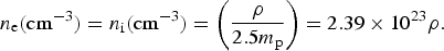 $${n_{\rm e}}{\rm (c}{{\rm m}^{ - 3}}) = {n_{\rm i}}{\rm (c}{{\rm m}^{ - 3}}) = \left( {\displaystyle{{\rm \rho} \over {2.5{m_{\rm p}}}}} \right) = 2.39 \times {10^{23}}{\rm \rho}. $$
The α-particles (α) created in the nuclear fusion reactions
 $$D + T \to n + {\rm \alpha} + 17,589\,{\rm keV}$$
supply the ignitor energy density rate W f
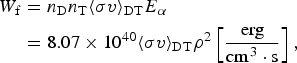 $$\eqalign{{W_{\rm f}} & = {n_{\rm D}}{n_{\rm T}}{\langle {\rm \sigma} v\rangle _{{\rm DT}}}{E_{\rm \alpha}} \cr & = 8.07 \times {10^{40}}{\langle {\rm \sigma} v\rangle _{{\rm DT}}}{{\rm \rho} ^2}\left[ {\displaystyle{{{\rm erg}} \over {{\rm c}{{\rm m}^3} \cdot {\rm s}}}} \right],} $$
where σ is the DT fusion cross-section, v is the relative DT velocity, and 〈σv〉 is the relevant average for the process under consideration. This velocity is achieved by a high-intensity laser-induced shock wave. 〈σv〉DT, the reactivity of the DT reaction fitted in the domain of ion temperatures 1 keV <T i < 100 keV, is given by (Bosch & Hale, Reference Bosch and Hale1992)
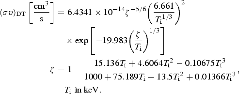 $$\eqalign{{\langle {\rm \sigma} v\rangle _{{\rm DT}}}\left[ {\displaystyle{{{\rm c}{{\rm m}^3}} \over {\rm s}}} \right] &= 6.4341 \times {10^{ - 14}}{{\rm \zeta} ^{ - 5/6}}{\left( {\displaystyle{{6.661} \over {{T_{\rm i}}^{1/3}}}} \right)^2} \cr & \quad\times {\rm exp}\left[ { - 19.983{{\left( {\displaystyle{{\rm \zeta} \over {{T_{\rm i}}}}} \right)}^{1/3}}} \right] \cr {\rm \zeta} &= 1 - \displaystyle{{15.136{T_{\rm i}} + 4.6064{T_{\rm i}}^2 - 0.10675{T_{\rm i}}^3} \over {1000 + 75.189{T_{\rm i}} + 13.5{T_{\rm i}}^2 + 0.01366{T_{\rm i}}^3}}, \cr & \quad {T_{\rm i}}\,\,\hbox{in keV}.} $$
The ignitor performance can be analyzed by an energy balance, dependent on the ions and electrons temperatures T i and T e (Chu, Reference Chu1972; Eliezer & MartinezVal, Reference Eliezer and Martinez Val1998; Eliezer et al., Reference Eliezer, Henis, Nissim, Pinhasi Vinikman and Martinez Val2015)
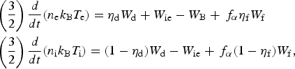 $$\eqalign{& \left( {\displaystyle{3 \over 2}} \right)\displaystyle{d \over {dt}}({n_{\rm e}}{k_{\rm B}}{T_{\rm e}}) = {{\rm \eta} _{\rm d}}{W_{\rm d}} + {W_{{\rm ie}}} - {W_{\rm B}} + {\,f_{\rm \alpha}} {{\rm \eta} _{\rm f}}{W_{\rm f}} \cr & \left( {\displaystyle{3 \over 2}} \right)\displaystyle{d \over {dt}}({n_{\rm i}}{k_{\rm B}}{T_{\rm i}}) = (1 - {{\rm \eta} _{\rm d}}){W_{\rm d}} - {W_{{\rm ie}}} + {\,f_{\rm \alpha}} (1 - {{\rm \eta} _{\rm f}}){W_{\rm f}},} $$
k B is the Boltzmann constant. W d [erg/(cm3·s)] is the power density deposited by the driver (induced by the laser–piston in our case), ηd equals the fraction of the driver energy deposited in the electrons inside the shocked volume, 1 – ηd gives the fraction of the driver energy deposited in the ions inside the shocked volume. W ie [erg/(cm3·s)] is the ion–electron exchange power density, whereas W B [erg/(cm3·s)] describe the electron bremsstrahlung power density losses. As described above, W f [erg/(cm3·s)] equals the fusion power density created in the shocked volume, where f α gives the fraction of the α-particles energy deposited inside the shocked volume with ηf equals the energy fraction that is deposited in the electrons by the α-particles and (1 − ηf) is the energy fraction that is deposited in the ions by the α-particles.
The shock wave velocity (u s) and the flow particle velocity (u p) in this scheme are in the intermediate domain between the relativistic and non-relativistic values (see the Appendix). The shock wave driver considered here is a laser-piston, which pushes the DT plasma to move with velocity u p. The deposition power density W d in this piston model with a constant laser irradiance I L[W/cm2] and laser pulse duration τL is given by
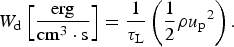 $${W_{\rm d}}\left[ {\displaystyle{{{\rm erg}} \over {{\rm c}{{\rm m}^3} \cdot {\rm s}}}} \right] = \displaystyle{1 \over {{{\rm \tau} _{\rm L}}}}\left( {\displaystyle{1 \over 2}{\rm \rho} {u_{\rm p}}^2} \right).$$
The fraction of the driver energy deposition into the electrons ηd can be estimated as function of λi and λe, the appropriate mean-free paths of the ions and electrons in plasma:
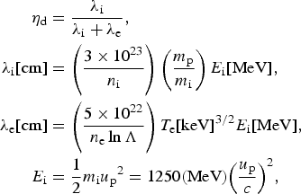 $$\eqalign{{{\rm \eta} _{\rm d}} & = \displaystyle{{{{\rm \lambda} _{\rm i}}} \over {{{\rm \lambda} _{\rm i}} + {{\rm \lambda} _{\rm e}}}}, \cr {{\rm \lambda}_{\rm i}}[{\rm cm}]& = \left( {\displaystyle{{3 \times {{10}^{23}}} \over {{n_{\rm i}}}}} \right)\left( {\displaystyle{{{m_{\rm p}}} \over {{m_{\rm i}}}}} \right){E_{\rm i}}[{\rm MeV}], \cr {{\rm \lambda} _{\rm e}}[{\rm cm}]& = \left( {\displaystyle{{5 \times {{10}^{22}}} \over {{n_{\rm e}}\ln \Lambda}}} \right){T_{\rm e}}{[{\rm keV}]^{3/2}}{E_{\rm i}}[{\rm MeV],} \cr {E_{\rm i}} & = \displaystyle{1 \over 2}{m_{\rm i}}{u_{\rm p}}^2 = 1250({\rm MeV}){\left( {\displaystyle{{{u_{\rm p}}} \over c}} \right)^2},} $$
where the ion mass in our case is m i = 2.5 mp, the ion density n i is defined in Eq. (1) and the plasma logarithmic term lnΛ is
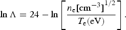 $$\ln \Lambda = 24 - \ln \left[ {\displaystyle{{{n_{\rm e}}{{[{\rm c}{{\rm m}^{ - 3}}]}^{1/2}}} \over {{T_{\rm e}}({\rm eV})}}} \right].$$
It is important to mention that although λi and λe can in general be larger than the time-dependent shocked domain u p·t, the charged particles that heat the shocked region have a velocity u p and therefore are not moving faster than the shock wave since u s > u p. Thus, the shock wave moves into a cold domain not yet heated by the driver energy.
The ion–electron exchange power density is given by
 $$\eqalign{& {W_{{\rm ie}}}\left[ {\displaystyle{{{\rm erg}} \over {{\rm c}{{\rm m}^3} \cdot {\rm s}}}} \right] = \left( {\displaystyle{3 \over 2}} \right)\displaystyle{{{k_{\rm B}}({T_{\rm i}} - {T_{\rm e}})} \over {{{\rm \tau} _{{\rm eq}}}}}, \cr & {{\rm \tau} _{{\rm eq}}} = \displaystyle{{3\,{m_{\rm e}}{m_{\rm i}}} \over {8\sqrt {2{\rm \pi}} {n_{\rm i}}{e^4}{\rm ln\Lambda}}} {\left( {\displaystyle{{{k_{\rm B}}{T_{\rm e}}} \over {{m_{\rm e}}}} + \displaystyle{{{k_{\rm B}}{T_{\rm i}}} \over {{m_{\rm i}}}}} \right)^{3/2}}.} $$
The bremsstrahlung power density losses W B are given by
 $${W_{\rm B}}\left[ {\displaystyle{{{\rm erg}} \over {{\rm c}{{\rm m}^3} \cdot {\rm s}}}} \right] = 8.58 \times {10^{21}}{{\rm \rho} ^2}{T_{\rm e}}{({\rm eV})^{0.5}}\left( {1 + \displaystyle{{2{T_{\rm e}}({\rm eV})} \over {0.511 \times {{10}^6}}}} \right).$$
The α fusion energy is defined in Eq. (3). However, not all of the α fusion energy is deposited into the ignitor; f α is the fraction of the α-particles created and deposited into the ignitor domain, while (1–f α) is the escape fraction to the surrounding cold fuel. The value of f α is (Guskov & Rozanov, Reference Guskov, Rozanov, Velarde, Ronen and Martinez Val1993)
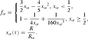 $$\eqalign{{\,f_{\rm \alpha}} & = \left\{ \matrix{\displaystyle{3 \over 2}{x_{\rm \alpha}} - \displaystyle{4 \over 5}{x_{\rm \alpha}} ^2 {\rm,} \; {x_{\rm \alpha}} \lt \displaystyle{1 \over 2}, \hfill \cr 1 - \displaystyle{1 \over {4{x_{\rm \alpha}}}} + \displaystyle{1 \over {160{x_{\rm \alpha}} ^3}} {\rm,} \; {x_{\rm \alpha}} \ge \displaystyle{1 \over 2}, \hfill} \right. \cr & {x_{\rm \alpha}} ({\rm \tau} ) = \displaystyle{R \over {{R_{\rm \alpha}}}}.} $$
The ignitor dimension R in our model is taken to be the length of the shocked cylinder
 $$\; R = {l_{\rm s}} = ({u_{\rm s}}{\rm -} {u_{\rm p}}){{\rm \tau} _{\rm L}},$$
and the α range R α is approximated (Atzeni & Meyer-Ter-Vehn, Reference Atzeni and Meyer-Ter-Vehn2004) by:
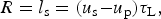
 $${\rm} {R_{\rm \alpha}} [{\rm cm}] = \displaystyle{1 \over {{\rm \kappa} {{\rm \rho} _0}}}\left[ {\displaystyle{{1.5 \times {{10}^{ - 2}}{T_{\rm e}}{{({\rm keV})}^{5/4}}} \over {1 + 8.2 \times {{10}^{ - 3}}{T_{\rm e}}{{({\rm keV})}^{5/4}}}}} \right].$$
The initial density of the pre-compressed target is ρ0 and κ is the shock wave compression.
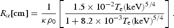
The fusion energy fraction deposited in the electrons by the α-particles is ηf and (1 − ηf) describes the energy fraction that is deposited in the ions. The function ηf for DT fusion is (Chu, Reference Chu1972):
 $${{\rm \eta} _{\rm f}} = \displaystyle{{32} \over {32 + {T_{\rm e}}({\rm keV})}}.$$
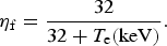
The time-dependent temperatures in Eq. (5) are coupled to equations for the number densities of the ions species. For DT these equations in our case (n D = n T) are:
 $$\displaystyle{{d{n_{\rm D}}} \over {dt}} = \displaystyle{{d{n_{\rm T}}} \over {dt}} = - \displaystyle{{d{n_{\rm \alpha}}} \over {dt}} = - {n_{\rm D}}{n_{\rm T}}{\langle {\rm \sigma} {\rm v}\rangle _{{\rm DT}}},$$
where n D, n T, and n α are number densities of the deuterons, tritium, and α-particles accordingly and 〈σv〉DT is given in Eq. (4).
We solve Eqs. (5) and (15) numerically and the calculated electron and ion temperatures are given in Figure 1, while the number densities of deuterium, tritium, and α are specified in Figure 2. Our input data for these calculations are:
1. A pre-compressed target of DT with initial density ρ0 and shocked density ρ = 3600 g/cm3 and initial temperature (in energy units) of T e = T i = 1 keV.
2. The ratio of heat capacity at constant pressure to heat capacity at constant volume Γ in the laser-induced shock wave is either 3 or 5/3 and Γ = 3 for the detonation wave (Landau & Stanyukovich, Reference Landau and Stanyukovich1945) as described in the next section. Therefore, the compression κ = (Γ + 1)/(Γ − 1) is either 2 or 4 (see the Appendix), equivalent to pre-compressed density ρ0, 1800 or 900 g/cm3 accordingly. As the released fusion energy is dependent on the shocked region density, to compare the ignitor performance corresponding to the above two values of Γ, we choose similar value for the shocked density.
3. For both the values of Γ that we consider, we have a particle flow velocity u p in the shock wave that equals to 0.010c, where c is the speed of light. As shown in the Appendix, the value of laser intensity particle I L (W/cm2), the initial density ρ0 and the equation-of-state (EOS) parameter Γ determines the particle flow velocity and the shock wave velocity as well as the compression (which depends only on Γ in the domain discussed here). The laser pulse duration was adjusted to obtain the required fusion energy Q (see Section 3) for the development of detonation wave at the end of the laser pulse. Assuming a laser spot radius R L = 1.5 l s [see Eq. (12) and the Appendix], the required laser energy can be estimated by
(16) $$W_{\rm L} = {\rm \pi} R_{\rm L}^2I_{\rm L}{\rm \tau}_{\rm L}.$$

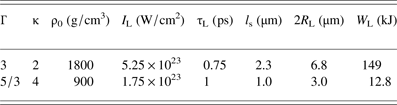
The values of the laser parameters leading to detonation development at the end of the laser pulse for the two values of Γ are given in Table 1.

Fig. 1. Electrons and ions temperatures as a function of time for a shock wave induced by (a) a laser irradiance and energy of I L = 5.25 × 10²³ W/cm2 and 149 kJ accordingly during 0.75 ps assuming Γ = 3, in a pre-compressed target with density 1800 g/cm3, (b) a laser irradiance and energy of I L = 1.75 × 10²³ W/cm2 and 12.8 kJ accordingly during 1.0 ps assuming Γ = 5/3, in a pre-compressed target with density 900 g/cm3.
Fig. 2. The number densities of deuterium (n D), tritium (n T = n D), and α (n α) particles as a function of time in the shocked volume considered in Figure 1 for (a) Γ = 3, and (b) Γ = 5/3.
Table 1. Laser and shocked region parameters enabling the development of detonation at the end of the laser pulse for particle velocity u p = 0.01c.
From the solution of the time-dependent equations for the particles number density and temperatures, the fusion energy Q per unit mass released in the forward direction (defined by the shock front) by the end of the laser pulse duration is calculated. In our 1D piston model, f α is the fraction of the α-particles deposited into the ignitor domain, while (1–f α)/2 is the escape fraction into the forward cold fuel. The α mean-free path R α (front) in the front of the shock wave, with T e = 1 keV from the pre-compressed conditions, is according to Eq. (13)
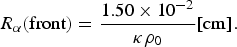 $${R_{\rm \alpha}} ({\rm front}) = \displaystyle{{1.50 \times {{10}^{ - 2}}} \over {{\rm \kappa} {{\rm \rho} _0}}}[{\rm cm}].$$
For a pre-compressed density of 1800 g/cm3, one gets R α (front) = 0.08/κ µm. Since this mean-free path is extremely small, we can assume that by the end of the laser pulse duration we have in the forward direction of the ignitor a fraction [f α + (1–f α/2)] of the fusion created α-particles each with an energy E α = 3.52 MeV. Thus, the α energy per unit mass Q given by
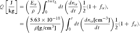 $$\eqalign{Q\left[ {\displaystyle{{\rm J} \over {{\rm kg}}}} \right] & = \left( {\displaystyle{{{E_{\rm \alpha}}} \over {\rm \rho}}} \right)\int_0^{t = {{\rm \tau} _L}} {dt\left( {\displaystyle{{d{n_{\rm \alpha}}} \over {dt}}} \right)} \displaystyle{1 \over 2}(1 + {\,f_{\rm \alpha}} ), \cr & = \left( {\displaystyle{{5.63 \times {{10}^{ - 10}}} \over {{\rm \rho} [{\rm g/c}{{\rm m}^3}]}}} \right)\int_0^t {dt\left( {\displaystyle{{d{n_{\rm \alpha}} [{\rm c}{{\rm m}^{ - 3}}]} \over {dt}}} \right)} \displaystyle{1 \over 2}(1 + {\,f_{\rm \alpha}} ).} $$
Our solutions for f α and Q are given in Figures 3 and 4 accordingly.
Fig. 3. The fusion energy fraction f α deposited in the shocked volume as a function of time in the shocked volume considered in Figure 1 for (a) Γ = 3, and (b) Γ = 5/3.
Fig. 4. The fusion energy Q per unit mass released in the shock wave forward direction as a function of time in the shocked volume considered in Figure 1 for (a) Γ = 3, and (b) Γ = 5/3.
3. THE DETONATION WAVE
At the end of the ignitor laser operation, we have chosen a particle velocity behind the shock front of 1.0% the speed of light. Now we will examine the conditions needed to support a steady detonation wave. The theoretical treatment that we consider is based on 1D plane detonation wave under Chapman–Jouguet (CJ) condition.
In the case of chemical-based detonation, the energetic material entering the shock front is compressed and thus its temperature rises. Under sufficient temperature the material transforms exothermally into gasses products releasing energy per unit mass (Q) that supports the shock. The section at which this reaction undergoes is called the reaction zone, and it is on the order of 0.1 mm for most explosives. The governing parameter effecting reaction rate in the reaction zone are the local density and temperature. Our detonation is analogous to this description where the chemical energy has been changed to nuclear fusion energy. In the DT fusion one gets 17.6 MeV fusion energy per reaction but only the 3.52 Mev of the α-particle is relevant to support the desired steady-state shock condition with a mean-free path <0.1 µm (see Eq. (17)).
The conservation laws of mass (flow of mass), momentum (sum of the flow of momenta), and energy (the sum of the flows of thermal, chemical, and kinetic energies and the work of the pressure force) are given by the following equations, respectively:
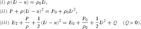 $$\eqalign{ &(i)\;{\rm}{\rm \rho} (D - u) = {{\rm \rho} _0}D, \cr & (ii)\;{\rm} P + {\rm \rho} {(D - u)^2} = {P_0} + {{\rm \rho} _0}{D^2}, \cr & (iii)\;{\rm} {E_{\rm T}} + \displaystyle{P \over {\rm \rho}} + \displaystyle{1 \over 2}{(D - u)^2} = {E_0} + \displaystyle{{{P_0}} \over {{{\rm \rho} _0}}} + \displaystyle{1 \over 2}{D^2} + Q\quad{\rm (}Q{\rm \gt 0)}{\rm.}} $$
P[erg/cm3] is the pressure, ρ[g/cm3] is the density, E T[erg/g] is the thermal energy, Q[erg/g] is the nuclear fusion energy deposited on the wave front, u is the velocity of motion of the fluid [cm/s], and D [cm/s] is the detonation wave velocity.
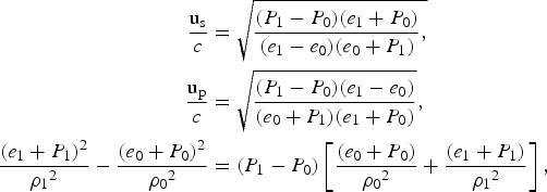
The detonation wave is steadily propagating with velocity D, namely all magnitudes P, ρ, u, and E T are functions of time t and space x only in the form x−D t. By using CJ formalism for the ideal gas case one can obtain from the conservation Eq. (19) some useful relations (Browne et al., Reference Browne, Ziegler and Shepherd2008):
 $$\eqalign{{\left( {\displaystyle{{\rm \rho} \over {{{\rm \rho} _0}}}} \right)_{{\rm CJ}}} & = \displaystyle{{\Gamma + 1} \over \Gamma} ;{P_{{\rm CJ}}} = \displaystyle{{{{\rm \rho} _0}{D^2}} \over {\Gamma + 1}}, \cr \displaystyle{u \over D}& = \displaystyle{1 \over {\Gamma + 1}};\displaystyle{{{c_{\rm s}}} \over D} = \displaystyle{\Gamma \over {\Gamma + 1}}, \cr \displaystyle{Q \over {{D^2}}} &= \displaystyle{{(\Gamma - 1)} \over {2{{(\Gamma + 1)}^2}}},} $$
where c s is the adiabatic sound velocity and Γ = C P/C V is the ratio of heat capacity at constant pressure to heat capacity at constant volume. For the detonation wave, we take Γ = 3 (Landau & Stanyukovich, Reference Landau and Stanyukovich1945) implying
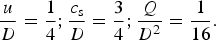 $$\displaystyle{u \over D} = \displaystyle{1 \over 4};\displaystyle{{{c_{\rm s}}} \over D} = \displaystyle{3 \over 4};\displaystyle{Q \over {{D^2}}} = \displaystyle{1 \over {16}}.$$
We can see that by determining the particle velocity u = u p to equal 1.0% the speed of light we have determined the nuclear energy needed to support a steady state CJ condition, Q = 9·1012 J/kg. As one can see from Figure 4, this value of Q is achieved by our laser-induced detonator.
It is interesting to point out that in the detonation wave for u/c = 0.01 we have D/c = 0.04, while the α released in the DT fusion with an energy of 3.5 MeV has a velocity of (u + v α)/c = 0.052. This implies that some of the α-particles will reach the detonation front.
4. CONCLUSION
In this paper, we have shown that a detonation wave can be derived by a laser-induced detonator. The energy in this detonation is supplied by the α-particles created in the fusion of DT. The fusion ignition is triggered by a laser-induced shock wave in a pre-compressed DT fuel that is able to supply the desired steady-state detonation criteria. The shock wave parameters in the detonator are in the intermediate domain between relativistic and non-relativistic hydrodynamics (see the Appendix).
The laser energy is W L = I LτLS L, where I L, τL, and S L are the laser irradiance, the pulse time duration and cross-section accordingly. The laser cross-section S L = πR L2 is chosen in such a way that the 1D laser-induced shock wave is conceivable. In particular, we take R L = 1.5(u s–u p)τL. In our domain of interest, the shock wave is between the relativistic and non-relativistic hydrodynamics, where Eq. (A13) determine the shock velocity u s and particle velocity u p as a function of laser irradiance I L, the initial target density ρ0, and the EOS parameter Γ (see the Appendix).
The laser parameters creating the ignitor depend strongly on the EOS. We consider an ideal gas with Γ = 5/3 and 3. The simulation shows that for the case (a) Γ = 3 and a pre-compressed target at 1800 g/cm3 (equal to an ion density of n i = 4.3 × 1026 cm−3) a laser irradiance I L = 5.25 × 10²³ W/cm2 and energy 149 kJ during 0.75 ps creates an α heating fusion detonation wave; while (b) for Γ = 5/3 and a pre-compressed target 900 g/cm3, the detonation wave requires a laser irradiance I L = 1.75 × 10²³ W/cm2 and energy 13.1 kJ during 1 ps.
Although the detonator EOS may be described by Γ = 5/3 or 3 the detonation wave has Γ = 3 following the original idea of Landau (Landau & Stanyukovich, Reference Landau and Stanyukovich1945). The laser-induced ignitor should supply the steady state CJ conditions as described by Eq. (21). In particular, we get that the α-particles created in the DT fusion by the end of the ignitor produce a power flux of W CJ = Qρ0u = 4.86 × 1025 W/m2, where Q = 9 × 10¹² J/kg.
The nuclear fusion burn is described by Figure 2. We achieve a detonation wave when the numbers of DT reactions are between 15% and 25% with an α density number of about 1026 cm−3.
To conclude we suggest that the detonation wave created by the laser-induced shock wave can ignite a pre-compressed DT pellet. The required ignition criterion of DT ignition and burn are easily satisfied (Atzeni & Meyer-Ter-Vehn, Reference Atzeni and Meyer-Ter-Vehn2004; Eliezer et al., Reference Eliezer, Henis, Nissim, Pinhasi Vinikman and Martinez Val2015) along the detonation wave trajectory.
In Figure 5, we show a schematic view of the detonation trajectory in a pre-compressed pellet. As a numerical example an initial pellet with radius R 0 = 1 mm and DT fuel of density 0.2 g/cm3 with thickness 0.1 mm (i.e., an aspect ratio of 10) is compressed to a density of ρ0 = 900 g/cm3 by the nanosecond lasers. The novel aspect of this ignition is the possibility to ignite the compressed pellet from inside and not from the surface as usually suggested. The compression of a typical pellet as discussed in the literature (Eliezer et al., Reference Eliezer, Murakami and Martinez Val2007) requires between 100 and 300 kJ of energy depending on the EOS, target design, and the final required density. The fast ignition in our case needs about 13 kJ of energy. Such a laser is under development and may be available in the near future (ELI, 2015).
Fig. 5. A schematic view of the detonation trajectory in a pre-compressed pellet. As a numerical example an initial pellet with radius R 0 = 1 mm and DT fuel of density 0.2 g/cm3 with thickness 0.1 mm (i.e., an aspect ratio of 10) is compressed to a density of ρ0 = 1800 g/cm3 by the nanosecond lasers.
APPENDIX
BETWEEN RELATIVISTIC AND NON-RELATIVISTIC SHOCK WAVES
In this appendix, we discuss the intermediate domain between relativistic and non-relativistic shock waves.
The three relativistic shock wave conservation laws (mass, momentum, and energy) in the laboratory frame of reference yield the following relations (Eliezer et al., Reference Eliezer, Nissim, Raicher and Martinez Val2014b):
 $$\eqalign{\displaystyle{{{{\rm u}_{\rm s}}} \over c} & = \sqrt {\displaystyle{{({P_1} - {P_0})({e_1} + {P_0})} \over {({e_1} - {e_0})({e_0} + {P_1})}},} \cr \displaystyle{{{{\rm u}_{\rm p}}} \over c}& = \sqrt {\displaystyle{{({P_1} - {P_0})({e_1} - {e_0})} \over {({e_0} + {P_1})({e_1} + {P_0})}}}, \cr \displaystyle{{{{({e_1} + {P_1})}^2}} \over {{{\rm \rho} _1}^2}} - \displaystyle{{{{({e_0} + {P_0})}^2}} \over {{{\rm \rho} _0}^2}}& = ({P_1} - {P_0})\left[ {\displaystyle{{({e_0} + {P_0})} \over {{{\rm \rho} _0}^2}} + \displaystyle{{({e_1} + {P_1})} \over {{{\rm \rho} _1}^2}}} \right],}$$
where P, e, and ρ are the pressure, energy density, and mass density accordingly, the subscripts 0 and 1 denote the domains before and after the shock arrival, u s is the shock wave velocity, u p is the particle flow velocity in the laboratory frame of reference, and c is the speed of light. We have assumed that in the laboratory the target is initially at rest, u p0 = 0. The last of Eq. (A1) is known as the Hugoniot equation. The EOS taken here in order to calculate the shock wave parameters is the ideal gas EOS
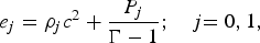 $${e_j} = {{\rm \rho} _j}{c^2} + \displaystyle{{{P_j}} \over {\Gamma - 1}};\quad {\rm} j{\rm = 0,1,}$$
where Γ is the specific heat ratio. We have to solve Eqs. (A1) and (A2) together with our piston model equation (Esirkepov et al., Reference Esirkepov, Borghesi, Bulanov, Mourou and Tajima2004; Eliezer et al., Reference Eliezer, Nissim, Raicher and Martinez Val2014b)
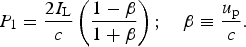 $${P_1} = \displaystyle{{2{I_{\rm L}}} \over c}\left( {\displaystyle{{1 - {\rm \beta}} \over {1 + {\rm \beta}}}} \right);\quad {\rm \beta} \equiv \displaystyle{{{u_{\rm p}}} \over c}.$$
The calculations are conveniently done in the dimensionless units defined by
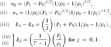
 $${\Pi _{\rm L}} \equiv \displaystyle{{{I_{\rm L}}} \over {{{\rm \rho} _0}{c^3}}};\;{\rm \kappa} \equiv \displaystyle{{{{\rm \rho} _1}} \over {{{\rm \rho} _0}}};\;{{\rm \kappa} _0} \equiv \displaystyle{{\Gamma + 1} \over {\Gamma - 1}};\;\Pi = \displaystyle{{{P_1}} \over {{{\rm \rho} _0}{c^2}}};\;{\Pi _0} = \displaystyle{{{P_0}} \over {{{\rm \rho} _0}{c^2}}}.$$
It is important to emphasize that if we take P 0 = 0, then we get only the κ > 4 solutions (Eliezer et al., Reference Eliezer, Nissim, Pinhasi, Raicher and Martinez Val2014a); therefore, in order to see the behavior at the transition between relativistic and nonrelativistic domains one has to take P 0 ≠ 0! In this case, we get from Eqs. (A1) and (A2) the following equation relating dimensionless shock wave pressure Π with the compression κ, namely the relativistic Hugoniot equation for an ideal gas EOS is
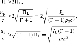
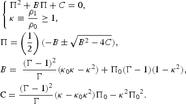 $$\eqalign{& \left\{ \matrix{{\Pi ^2} + B\Pi + C = 0, \hfill \cr {\rm \kappa} \equiv \displaystyle{{{{\rm \rho}_1}} \over {{{\rm \rho} _0}}} \ge 1, \hfill} \right.{\rm} \cr & \Pi = \left( {\displaystyle{1 \over 2}} \right)( - B \pm \sqrt {{B^2} - 4C} ), \cr & B = \;\displaystyle{{{{(\Gamma - 1)}^2}} \over \Gamma} ({{\rm \kappa} _0}{\rm \kappa} - {{\rm \kappa} ^2}) + {\Pi _0}(\Gamma - 1)(1 - {{\rm \kappa} ^2}), \cr & {\rm C =}\; \displaystyle{{{{(\Gamma - 1)}^2}} \over \Gamma} ({\rm \kappa} - {{\rm \kappa} _0}{{\rm \kappa} ^2}){\rm} {\Pi _0} - {{\rm \kappa} ^2}{\Pi _0}^2.}$$
The solution of this equation is shown in Figure 6 for Γ = 5/3. As one can see from Figure 6, the compression κ = ρ/ρ0 is constant in a large domain of the dimensionless pressure Π = P/(ρ0c 2), where P is the shock wave pressure. Therefore, for the intermediate relativistic shock wave, we have to a good (as desired) approximation the following relation:
 $${\rm \kappa} \equiv \displaystyle{{{{\rm \rho} _1}} \over {{{\rm \rho} _0}}} = {{\rm \kappa} _0} = \displaystyle{{\Gamma + 1} \over {\Gamma - 1}}.$$
Fig. 6. The shock wave compression κ = ρ/ρ0 as a function of the dimensionless shock wave pressure Π = P/ρ0c 2 for Γ = 5/3.
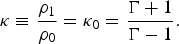
The non-relativistic shock wave equations are obtained from the relativistic Eq. (A1) using e = ρc 2 + ρE, P, and ρE are much smaller than ρc 2 and u/c ≪ 1, where u stands for the velocities under consideration. The appropriate non-relativistic equations describing the shock wave in the laboratory frame of reference are (Zeldovich & Raizer, Reference Zeldovich and Raizer1966).
 $$\eqalign{&(i)\quad u_{\rm p} = ({P_1} - {P_0})^{1/2}(1/{\rm \rho}_0 - 1/{\rm \rho}_1)^{1/2}, \cr & (ii) \quad u_{\rm s} = (1/{\rm \rho}_0)({P_1} - {P_0})^{1/2}(1/{\rm \rho}_0 - 1/{\rm \rho}_1)^{ - 1/2}, \cr & (iii) \quad E_1 - E_0 = \left( {\displaystyle{1 \over 2}} \right)({P_1} + {P_0})(1/{\rm \rho}_0 - 1/{\rm \rho}_1), \cr & \left. \matrix{(iv) \hfill \cr (v) \hfill} \right\}{E_j} = \left( {\displaystyle{1 \over {\Gamma - 1}}} \right)\left( {\displaystyle{{P_j} \over {{\rm \rho}_j}}}\right)\;{\rm for} \;j\;=\; 0,1.}$$
The relativistic Hugoniot equation for an ideal gas EOS is given by Eq. (A5), while the non-relativistic Hugoniot equation for an ideal gas EOS is [from (A7)]
 $$\Pi = \left( {\displaystyle{{{\rm \kappa} {{\rm \kappa} _0} - 1} \over {{{\rm \kappa} _0} - {\rm \kappa}}}} \right){\Pi _0}.$$
Figure 6 describes the transition between the relativistic and non-relativistic Hugoniot, namely the transition between Eqs. (A5) and (A8). In this transition domain, between relativistic and non-relativistic shock waves, we have
 $${10^{ - 9}} \le \Pi \le {10^{ - 3}} \Leftrightarrow {\rm \kappa} = \displaystyle{{\rm \rho} \over {{{\rm \rho} _0}}} = 4.00{\rm \ (for} \ \Gamma = {\rm 5/3)}$$
In the domain defined by Eq. (A6) (yielding (A9) for Γ = 5/3), we can use the first two equations of (A7) for u p/c < 0.03 in order to get
 $$\eqalign{ \displaystyle{{{u_{\rm p}}} \over c} &= \sqrt {\displaystyle{{2\Pi} \over {\Gamma + 1}}} ; \cr & \hskip-10pt\displaystyle{{{u_{\rm s}}} \over c} = \sqrt {\displaystyle{{(\Gamma + 1)\Pi} \over 2}}.}$$
Using now our piston model Eq. (A3) together with Eq. (A10), we obtain
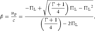 $${\rm \beta} = \displaystyle{{{u_{\rm p}}} \over c} = \displaystyle{{ - {\Pi _{\rm L}} + \sqrt {\left( {\displaystyle{{\Gamma + 1} \over 4}} \right){\Pi _{\rm L}} - {\Pi _{\rm L}}^2}} \over {\left( {\displaystyle{{\Gamma + 1} \over 4}} \right) - 2{\Pi _{\rm L}}}},$$
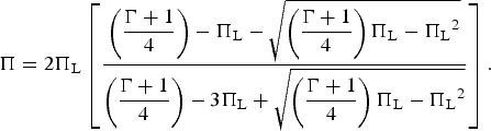 $$\Pi = 2{\Pi _{\rm L}}\left[ {\displaystyle{{\left( {\displaystyle{{\Gamma + 1} \over 4}} \right) - {\Pi _{\rm L}} - \sqrt {\left( {\displaystyle{{\Gamma + 1} \over 4}} \right){\Pi _{\rm L}} - {\Pi _{\rm L}}^2}} \over {\left( {\displaystyle{{\Gamma + 1} \over 4}} \right) - 3{\Pi _{\rm L}} + \sqrt {\left( {\displaystyle{{\Gamma + 1} \over 4}} \right){\Pi _{\rm L}} - {\Pi _{\rm L}}^2}}}} \right].$$
In Figures 7 and 8, we describe appropriately the dimensionless particle shock velocity β = u p/c and the dimensionless pressure Π = P/(ρ0c 2) as a function of the dimensionless laser intensity ΠL = I L/(ρ0c 3) for the two cases Γ = 3 and 5/3. An identical graph for Π as a function of ΠL is derived for Γ = 5/3, since the Γ dependence in this domain is negligible. Since ΠL < 10−2, we have to a good approximation in the domain between relativistic and non-relativistic shock waves the following approximations:
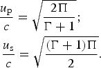
 $$\eqalign{\Pi \approx & 2{\Pi _{\rm L}}, \cr \displaystyle{{{u_{\rm p}}} \over c} \approx & 2\sqrt {\displaystyle{{{\Pi _{\rm L}}} \over {\Gamma + 1}}} = 2\sqrt {\displaystyle{{{I_{\rm L}}} \over {(\Gamma + 1){{\rm \rho} _0}{c^3}}}}, \cr \displaystyle{{{u_{\rm s}}} \over c} \approx & \sqrt {(\Gamma + 1){\Pi _{\rm L}}} = \sqrt {\displaystyle{{{I_{\rm L}}(\Gamma + 1)} \over {{{\rm \rho} _0}{c^3}}}.}}$$
Fig. 7. The dimensionless particle shock velocity β = u p/c as a function of the dimensionless laser intensity ΠL = I L/(ρ0c 3) for the two cases Γ = 3 and Γ = 5/3.
Fig. 8. The dimensionless shock wave pressure Π = P/(ρoc 2) as a function of the dimensionless laser intensity ΠL = I L/(ρ0c 3) for Γ = 3. An identical graph is derived for Γ = 5/3, since the Γ dependence in this domain is negligible.
Under this approximation, the shock wave length l s by the end of the laser pulse is
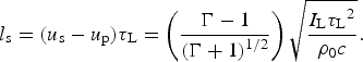 $${l_{\rm s}} = ({u_{\rm s}} - {u_{\rm p}}){{\rm \tau} _{\rm L}} = \left( {\displaystyle{{\Gamma - 1} \over {{{(\Gamma + 1)}^{1/2}}}}} \right)\sqrt {\displaystyle{{{I_{\rm L}}{{\rm \tau} _{\rm L}}^2} \over {{{\rm \rho} _0}c}}}.$$
The laser cross-section S L = πR L2 is chosen R L = 1.5(u s–u p) τL in order that the 1D laser-induced shock wave is conceivable. Therefore for a constant laser irradiation I L, we need a laser energy W L given by
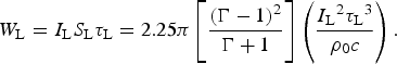 $${W_{\rm L}} = {I_{\rm L}}{S_{\rm L}}{{\rm \tau} _{\rm L}} = 2.25{\rm \pi} \left[ {\displaystyle{{{{(\Gamma - 1)}^2}} \over {\Gamma + 1}}} \right]\left( {\displaystyle{{{I_{\rm L}}^2 {{\rm \tau} _{\rm L}}^3} \over {{{\rm \rho} _0}c}}} \right).$$

