1 Introduction
Flow fields exhibiting shock reflection transition as discussed in this paper are placed in the context of the three-dimensional flow fields obtained when two wedges are placed symmetrically opposite each other in a wind tunnel test section, as shown in figure 1(a). This has become the conventional configuration for studying shock reflection and transition, with the horizontal symmetry plane acting as an idealised reflecting surface. Hornung (Reference Hornung1986) highlights the important effects on reflection transitions of boundary layers resulting from using a flat plate instead of a symmetry plane as well as reflecting surface roughness and porosity for two-dimensional cases. In general, the three-dimensional incident shock surface is swept backwards and downstream of the test pieces. The central regions of interaction may be regular (RR) with the sweep of the incident shock surface eventually transitioning to Mach reflection (MR) towards the peripheral regions of the flow field, as depicted in figure 1(b). This shock configuration is similar to that obtained with a body of revolution (Sears–Haack) in a supersonic free stream in close proximity to a ground plane as in figure 2. In comparison with figure 1(b), the central part of the intersection line is swept backwards to a greater extent. It is now known that the finite aspect ratio of the wedges gives rise to edge Mach cones which comprise edge expansion signals, and which in turn influence both the surface flow (figure 3 a) and shock interactions at the horizontal symmetry plane (Skews Reference Skews1997, Reference Skews2000) as in figure 3(b). An important result of edge effects is the swept portion of the incident wave, coloured yellow in figure 1(b), which is a consequence of the outward flow towards the wedge edges.
Previous works (Skews Reference Skews1997; Ivanov Reference Ivanov2000) have found such effects to be a contributing factor in the discrepancy between theoretical predictions and experimental results regarding two-dimensional shock transition. In such cases where wedge aspect ratios are lower than a certain limit, as specified by Skews (Reference Skews1997), the shock configuration at the vertical symmetry plane is fundamentally altered by these three-dimensional effects. This was confirmed by additional experimental work done by Sudani et al. (Reference Sudani, Sato, Karasawa, Noda, Tate and Watanabe2002). The realisation of the impact of edge effects enabled further advancements in resolving the aforementioned discrepancies noted for two-dimensional reflection transition studies. Perhaps the most important of these was the hysteresis phenomenon associated with the length-scale transition mechanism suggested by Hornung, Oertel & Sandeman (Reference Hornung, Oertel and Sandeman1979), which was experimentally demonstrated by Ivanov et al. (Reference Ivanov, Khotyanovsky, Kudryavtsev, Markelov, Nikiforov and Lu2001). Having understood the nature of influences of a three-dimensional flow field on investigations of two-dimensional reflection phenomena, further study by Kudryavtsev et al. (Reference Kudryavtsev, Khotyanovsky, Ivanov, Hadjadj and Vandromme2002) systematically explored the effects of disturbances on the transitional behaviour of the shock system for two-dimensional computational cases. In recent times, the three-dimensional nature of an interacting shock system has been studied by Huang et al. (Reference Huang, Wang, Pourkashanian, Ma, Ingham, Luo, Lei and Liu2011) in the context of a scramjet isolator. In this case, the nature of transition between Mach reflection and a normal shock regime as a result of back-pressure disturbances and geometrical variations was explored. It is important to note that the flow field depicted in figure 2 is not subjected to three-dimensional perturbations due to there being no edge on the body at which a Mach cone can exist to influence the reflection and transition phenomena.

Figure 1. (a) Overview of double-wedge configuration used in previous works with both symmetry planes indicated. (b) Overview of typical three-dimensional flow field with translucent surfaces marked I for incident wave, R for reflected wave, M for Mach surface, T for the transition point and S for shear surface. The intersection line is traced along the incident wave and Mach surface intersections with the horizontal symmetry plane.
Figure 2. Typical three-dimensional supersonic flow field obtained with a body in close proximity with a ground plane resulting in a highly swept intersection line (figure provided by B. W. Skews).

Figure 3. Mach cone and its effect on the flow in its vicinity. (a) Intersection of the Mach cone with the half-span wedge surface shown with a dotted line OP along the wedge surface with edge vortices indicated. (b) Intersection with incident shock surface shown with dotted line OQ.
For wedge bodies, the transition points further outwards at the peripheral regions (marked T in figure 1 b) are subjected to edge effects. The current work presents a study of flow fields with these transition points; however, the influence of edge effects has been intentionally eliminated. This was as a result of the test pieces used of the type as shown in figure 4(a,b). Figure 4(a) shows the original narrow low-transverse-spread model concept and figure 4(b) shows the formulation of wider models from later design iterations. The models are curved along their transverse length to eliminate the existence of edge Mach cones, with a backward sweep to provide a known geometrical boundary condition with which the sweep of the incident shock surface could be controlled. This resulted in considerable sweep along the entire length of the intersection line as seen in figure 2. The back and lower faces (the latter shown in figure 4 with plan elevations) were each formed using a non-uniform rational B-spline (NURBS) geometrical construction. A blending function was then used to loft and join the back and lower faces. The vertices of the NURBS formed a triangle ABC for the lower faces of all models. For the original concept, three vertices were used (triangle BCD). This was extended to polygons for later models (BCDEFG as in figure 4 b) to provide greater control over localised regions of the back face transverse spread. The blending function between the back and lower faces was implemented in a MATLAB script in order to formulate the codes for numerical control machining. Three models in addition to the original concept were used and designated 8, 10 and 11 in order of increasing transverse spread (see figure 5 a). The model numbers correspond to the design iteration as evolved from the original narrow low-spread concept. The types of flow fields discussed here are as shown in figure 5(b) and, although similar to figure 1, contain no edge perturbations influencing the shock reflections.

Figure 4. (a) Blending surface formation of original model concept. (b) Typical blending surface formation of models from later iterations (model 10 shown here). Dimensions in millimetres and angles in degrees.

Figure 5. (a) Typical test piece geometry for original concept and models 8, 10 and 11 in order of increasing spread. The models are oriented so that their back faces can be seen to give an idea of the geometrical spreads. (b) Typical flow field obtained with test models sketched up until the incident wave intersects the horizontal symmetry plane.
In this work, some fundamentals related to the intersection of planar shock surfaces in three-dimensional space will be considered initially. Next, these considerations are extended to the development of an analytical model describing the flow conditions on either side of the transition point. This is based on compatibility relations required to be satisfied across the transition point for physically tenable flow solutions. Some experimental and numerical results confirming the findings of the analytical model will be discussed. Finally, a discussion on the topology of the flow fields studied will be presented, in specific relation to model geometry and free-stream Mach-number dependences.
2 Regular three-dimensional planar shock interaction
2.1 Fundamentals
The theory of three-dimensional shock interaction is considered here, based primarily on the works of Migotsky & Morkovin (Reference Migotsky and Morkovin1951), Keldysh (Reference Keldysh1966) and Emanuel (Reference Emanuel2000). We consider a portion of a swept shock system the width of which is sufficiently small to approximate the waves as being planar, as shown in figure 6. The planar wave configuration of figure 6 may be realised for an infinitesimal segment of the swept wave surfaces of figure 5(b). The sweep angle
 $\unicode[STIX]{x1D6FD}$
is thus defined as the angle between the shock intersection line and the free-stream flow vector at Mach number
$\unicode[STIX]{x1D6FD}$
is thus defined as the angle between the shock intersection line and the free-stream flow vector at Mach number
 $M_{1}$
. It is emphasised that the definition of sweep used here is complementary to that defined in an aeronautical sense, for example, in relation to the sweep of a wing.
$M_{1}$
. It is emphasised that the definition of sweep used here is complementary to that defined in an aeronautical sense, for example, in relation to the sweep of a wing.

Figure 6. Standard configuration of planar shock wave interaction in three-dimensional space.
Upon reaching the incident shock plane, the free stream is deflected in three directional components, the most relevant of which is that projected onto plane
 $P_{A}$
. This is perpendicular to plane
$P_{A}$
. This is perpendicular to plane
 $P_{B}$
, shown in red and green, respectively, in figure 6. Plane
$P_{B}$
, shown in red and green, respectively, in figure 6. Plane
 $P_{A}$
is normal to the intersection line of the shock planes. Plane
$P_{A}$
is normal to the intersection line of the shock planes. Plane
 $P_{B}$
contains the free-stream vector
$P_{B}$
contains the free-stream vector
 $M_{1}$
and is parallel to the horizontal symmetry plane at which the incident and reflected shock surfaces meet. Plane
$M_{1}$
and is parallel to the horizontal symmetry plane at which the incident and reflected shock surfaces meet. Plane
 $P_{A}$
is of importance, and will be termed the analysis plane. This is because the two-dimensional oblique relations for shock waves and their interaction apply in plane
$P_{A}$
is of importance, and will be termed the analysis plane. This is because the two-dimensional oblique relations for shock waves and their interaction apply in plane
 $P_{A}$
, as long as all relevant quantities are projected onto this plane. Thus, an ostensibly complex three-dimensional interaction can be suitably reduced to an effective two-dimensional one, as per figure 7. The corresponding Mach-number component in this same plane is
$P_{A}$
, as long as all relevant quantities are projected onto this plane. Thus, an ostensibly complex three-dimensional interaction can be suitably reduced to an effective two-dimensional one, as per figure 7. The corresponding Mach-number component in this same plane is
 $M_{1}^{\prime }=M_{1}\sin \unicode[STIX]{x1D6FD}$
. It is important to note that the analysis-plane shock angle (effective shock angle) is defined as
$M_{1}^{\prime }=M_{1}\sin \unicode[STIX]{x1D6FD}$
. It is important to note that the analysis-plane shock angle (effective shock angle) is defined as
 $$\begin{eqnarray}\unicode[STIX]{x1D703}_{1}^{\prime }=\sin ^{-1}\left(\frac{\sin \unicode[STIX]{x1D703}_{1}}{\sin \unicode[STIX]{x1D6FD}}\right),\end{eqnarray}$$
where
 $\unicode[STIX]{x1D703}_{1}$
is the incident shock angle obtained as seen in a vertical slice of the flow field. The primes refer to effective quantities in the analysis plane. Calculations carried out in the analysis plane are analogous to that for two-dimensional oblique shocks in which vector components normal to the shock are considered to effect changes across the shock wave (Anderson Reference Anderson2001).
$\unicode[STIX]{x1D703}_{1}$
is the incident shock angle obtained as seen in a vertical slice of the flow field. The primes refer to effective quantities in the analysis plane. Calculations carried out in the analysis plane are analogous to that for two-dimensional oblique shocks in which vector components normal to the shock are considered to effect changes across the shock wave (Anderson Reference Anderson2001).
A detailed study on the analysis of a single three-dimensional swept wave surface was carried out by Domel (Reference Domel2016), which is applicable here to the incident wave surface and may be extended to apply to the reflected wave surface. Some interesting observations were made by Domel regarding the effect of sweep on the incident wave and post-shock flow deflections with the associated complexities consolidated into a new relation for shock geometry and post-shock parameters as a function of sweep, deflection angle and shock angle. This is analogous to the theta–beta–Mach number relation for a single oblique two-dimensional shock wave. In this study, the incident wave surface was intentionally made to vary in sweep across the entire span of the wave system. Therefore, planar relations for a single shock or system of interacting shocks is valid for an infinitesimal segment of the shock system in this work. The assumption of uniform regions in the analysis plane before and after the incident and reflected waves, usually applied to standard two-dimensional analyses, is considered reasonable for a localised region, especially very close to the symmetry plane and to the reflection point of the shock waves. Attention is now turned to the conditions of existence and transition in the analysis plane following a brief outline of transition phenomena in two-dimensional cases.

Figure 7. Reduction to analysis plane for regular reflection configuration.
2.2 Existence and transition criteria
The three-dimensional shock interaction detailed in this work bears close similarity with Domel’s approach inasmuch as the minimum criteria for the existence of a three-dimensional shock surface and analysis-plane computations are concerned. Two-dimensional reflection transition criteria suggest both the detachment and von Neumann conditions for transition between regular and Mach reflection. The former is reached when the reflected wave cannot turn the flow parallel to the reflecting surface and the shock intersection detaches from the symmetry plane, bridged by a Mach stem. The latter results from the post-reflection pressure for regular reflection reaching the upper limit permissible for a normal shock with the same free-stream flow conditions, after which further increases in angle for the incident shock results in a pressure increase that can only be sustained by the transition to Mach reflection (Ben-Dor Reference Ben-Dor2007).
It is important to note that, because of sweep, the analysis-plane component of the free-stream Mach number (i.e. the effective normal Mach number
 $M_{1}^{\prime }\sin \unicode[STIX]{x1D703}_{1}^{\prime }$
) is required to be high enough for the shocks in the analysis plane to exist. This puts limits on the extent of the sweep angle, or on the minimum free-stream Mach number
$M_{1}^{\prime }\sin \unicode[STIX]{x1D703}_{1}^{\prime }$
) is required to be high enough for the shocks in the analysis plane to exist. This puts limits on the extent of the sweep angle, or on the minimum free-stream Mach number
 $M_{1}$
, which reduce to
$M_{1}$
, which reduce to
 $$\begin{eqnarray}\frac{1}{M_{1}\sin \unicode[STIX]{x1D6FD}}\leqslant \sin \unicode[STIX]{x1D703}_{1}^{\prime }\leqslant \sin \unicode[STIX]{x1D703}_{1\,max}^{\prime },\end{eqnarray}$$
where
 $\unicode[STIX]{x1D703}_{1\,max}^{\prime }$
is to be defined as that wave angle beyond which Mach reflection is formed in the analysis plane, and is analogous to the detachment criterion for two-dimensional reflection transition. From the preceding inequality, two things are important: First, the normal Mach number component in the analysis plane is what governs the reflection transition and determines whether or not the shocks in the analysis plane exist or are so weak as to reduce to Mach waves. Secondly, theoretically the same transition criteria (i.e. von Neumann and detachment) apply to the analysis plane as with a purely two-dimensional interaction. The important difference here is that
$\unicode[STIX]{x1D703}_{1\,max}^{\prime }$
is to be defined as that wave angle beyond which Mach reflection is formed in the analysis plane, and is analogous to the detachment criterion for two-dimensional reflection transition. From the preceding inequality, two things are important: First, the normal Mach number component in the analysis plane is what governs the reflection transition and determines whether or not the shocks in the analysis plane exist or are so weak as to reduce to Mach waves. Secondly, theoretically the same transition criteria (i.e. von Neumann and detachment) apply to the analysis plane as with a purely two-dimensional interaction. The important difference here is that
 $\unicode[STIX]{x1D703}_{1\,max}^{\prime }$
is additionally dependent on
$\unicode[STIX]{x1D703}_{1\,max}^{\prime }$
is additionally dependent on
 $\unicode[STIX]{x1D6FD}$
and thus varies all along the intersection line for the flows considered here.
$\unicode[STIX]{x1D6FD}$
and thus varies all along the intersection line for the flows considered here.
The criteria for existence and transition between regular and Mach reflection in the analysis plane are shown in figure 8 for a free-stream Mach number
 $M_{1}=3.0$
. Higher Mach-number flows are given to a broader range of effective incident shock angles in which the shock waves both exist and are configured in a regular reflection pattern. The incident wave angles of the von Neumann and detachment criteria are denoted by
$M_{1}=3.0$
. Higher Mach-number flows are given to a broader range of effective incident shock angles in which the shock waves both exist and are configured in a regular reflection pattern. The incident wave angles of the von Neumann and detachment criteria are denoted by
 $\unicode[STIX]{x1D703}_{1vN}^{\prime }$
and
$\unicode[STIX]{x1D703}_{1vN}^{\prime }$
and
 $\unicode[STIX]{x1D703}_{1\,max}^{\prime }$
, respectively. It is apparent that these criteria in the analysis plane are not clearly distinguishable for most of the range of sweep angles from approximately
$\unicode[STIX]{x1D703}_{1\,max}^{\prime }$
, respectively. It is apparent that these criteria in the analysis plane are not clearly distinguishable for most of the range of sweep angles from approximately
 $50^{\circ }$
to
$50^{\circ }$
to
 $90^{\circ }$
at
$90^{\circ }$
at
 $M_{1}=3.0$
. The largest difference in effective shock angle is approximately
$M_{1}=3.0$
. The largest difference in effective shock angle is approximately
 $2^{\circ }$
, occurring near a sweep of
$2^{\circ }$
, occurring near a sweep of
 $\unicode[STIX]{x1D6FD}=90^{\circ }$
. This represents a situation in which the free stream is perpendicular to the intersection line of the shock planes.
$\unicode[STIX]{x1D6FD}=90^{\circ }$
. This represents a situation in which the free stream is perpendicular to the intersection line of the shock planes.

Figure 8. Minimum existence criteria and transition criteria (detachment,
 $\unicode[STIX]{x1D703}_{max}^{\prime }$
; von Neumann,
$\unicode[STIX]{x1D703}_{max}^{\prime }$
; von Neumann,
 $\unicode[STIX]{x1D703}_{vN}^{\prime }$
) for three-dimensional shocks,
$\unicode[STIX]{x1D703}_{vN}^{\prime }$
) for three-dimensional shocks,
 $M_{1}=3.0$
.
$M_{1}=3.0$
.
In order to complete the analysis of spatial phenomena by virtue of three-dimensional shock intersections, attention is given to flow deflections as viewed from a plan elevation view of the top of the intersection as shown in figure 9. Although the intersection is viewed from the top, the vectors on this diagram are not the components in the plane of the intersection line and still possess their out-of-plane components where applicable. Again, all quantities with a prime denote the vector component in the analysis plane. The velocity vector emerging from the reflected wave is not parallel to the free-stream vector when viewed in the plan view as in figure 9; however, both vectors are parallel to the symmetry plane (containing the line of intersection) when viewed in the analysis plane or in a vertical plane slice of the flow field. The angular difference between the two vectors is given by
 $$\begin{eqnarray}\unicode[STIX]{x1D70F}=\unicode[STIX]{x1D6FD}-\unicode[STIX]{x1D6FE},\end{eqnarray}$$
where
 $\unicode[STIX]{x1D6FE}$
is the angle between the emergent velocity vector and the line of intersection in the horizontal symmetry plane. From figure 7, the velocity ratio across the entire system of shocks in the analysis plane can be derived as
$\unicode[STIX]{x1D6FE}$
is the angle between the emergent velocity vector and the line of intersection in the horizontal symmetry plane. From figure 7, the velocity ratio across the entire system of shocks in the analysis plane can be derived as
 $$\begin{eqnarray}\frac{V_{3}^{\prime }}{V_{1}^{\prime }}=\frac{\cos \unicode[STIX]{x1D703}_{1}^{\prime }}{\cos (\unicode[STIX]{x1D703}_{1}^{\prime }-\unicode[STIX]{x1D6FF}_{1})}\frac{\cos \unicode[STIX]{x1D703}_{2}^{\prime }}{\cos (\unicode[STIX]{x1D703}_{2}^{\prime }-\unicode[STIX]{x1D6FF}_{1})}.\end{eqnarray}$$
Noting that all tangential velocity components are equal across the shock system, it can be seen that
 $$\begin{eqnarray}\frac{\tan \unicode[STIX]{x1D6FE}}{\tan \unicode[STIX]{x1D6FD}}=\frac{M_{3}^{\prime }}{M_{1}^{\prime }}=\frac{M_{3}\sin \unicode[STIX]{x1D6FE}}{M_{1}\sin \unicode[STIX]{x1D6FD}}=\frac{V_{3}^{\prime }}{V_{1}^{\prime }},\end{eqnarray}$$
which also demonstrates equivalence of the ratios of effective Mach numbers and velocity components in the analysis plane, as deduced from the work of Keldysh (Reference Keldysh1966). In addition, the second equality relates the effective Mach ratio to the actual Mach ratio, which underpins the analysis discussed later. Of importance is the fact that the foregoing analysis can be used to relate the flow conditions and flow geometry in the analysis plane to those found in the top view of figure 9. As such we have
 $$\begin{eqnarray}\tan \unicode[STIX]{x1D6FD}=\frac{\cos (\unicode[STIX]{x1D703}_{1}^{\prime }-\unicode[STIX]{x1D6FF}_{1})}{\cos \unicode[STIX]{x1D703}_{1}^{\prime }}\frac{\cos (\unicode[STIX]{x1D703}_{2}^{\prime }-\unicode[STIX]{x1D6FF}_{1})}{\cos \unicode[STIX]{x1D703}_{2}^{\prime }}\tan \unicode[STIX]{x1D6FE},\end{eqnarray}$$
which is of clear significance to the understanding of regular reflection in three-dimensional space, and not being limited to any one plane. Thus, the fundamentals of regular reflection have been introduced. This requires extension to consider the flow phenomena in the presence of a transition point.
Figure 9. Top view of the intersection of the shock planes.
3 Model of flow in the vicinity of three-dimensional shock interaction transition points
Here, the regions in the immediate vicinity of three-dimensional transition points are considered. Observing the shock system from above, the shock intersection in the horizontal symmetry plane is as shown in figure 10. This depicts transition at the point from which a shear layer emanates, shown as the dotted line in figure 10. To one side of the shear layer there is regular reflection and on the other there is Mach reflection. In the immediate surrounds of the shear layer there should theoretically be compatibility between pressure and flow deflections such that
 $$\begin{eqnarray}\displaystyle & \unicode[STIX]{x1D6FE}_{RR}=\unicode[STIX]{x1D6FE}_{MR}, & \displaystyle\end{eqnarray}$$
 $$\begin{eqnarray}\displaystyle & \unicode[STIX]{x1D70F}_{RR}=\unicode[STIX]{x1D70F}_{MR}, & \displaystyle\end{eqnarray}$$
 $$\begin{eqnarray}\displaystyle & p_{3RR}=p_{4MR}. & \displaystyle\end{eqnarray}$$
Subscripts
 $RR$
and
$RR$
and
 $MR$
denote quantities specific to the respective reflection type along the intersection bow wave. It is important to note that (3.1) is obtained due to the fact that the sweep angle
$MR$
denote quantities specific to the respective reflection type along the intersection bow wave. It is important to note that (3.1) is obtained due to the fact that the sweep angle
 $\unicode[STIX]{x1D6FD}$
for the RR and MR portions on the intersection bow wave are initially assumed identical, and in general
$\unicode[STIX]{x1D6FD}$
for the RR and MR portions on the intersection bow wave are initially assumed identical, and in general
 $\unicode[STIX]{x1D6FE}=\unicode[STIX]{x1D6FD}-\unicode[STIX]{x1D70F}$
. This assumption is now examined further in light of the fact that the compatibility relations (deflections and pressures) should hold for the flows behind both the Mach reflection and the regular reflection portions. This is the main thrust of this work which, as will be discussed later, has important consequences for the shock geometry and physical conditions in the surrounds of the transition points.
$\unicode[STIX]{x1D6FE}=\unicode[STIX]{x1D6FD}-\unicode[STIX]{x1D70F}$
. This assumption is now examined further in light of the fact that the compatibility relations (deflections and pressures) should hold for the flows behind both the Mach reflection and the regular reflection portions. This is the main thrust of this work which, as will be discussed later, has important consequences for the shock geometry and physical conditions in the surrounds of the transition points.

Figure 10. Top view of three-dimensional transition at the symmetry plane.
The flow fields in the analysis planes for the MR and RR configurations need to be considered in the immediate vicinity of their respective interaction points, and the situations considered are shown in figure 11. On the regular reflection side of the transition point
 $T$
, the analysis is constrained to a small vertical distance
$T$
, the analysis is constrained to a small vertical distance
 $\unicode[STIX]{x0394}z$
away from the symmetry plane in the limit
$\unicode[STIX]{x0394}z$
away from the symmetry plane in the limit
 $\unicode[STIX]{x0394}z\rightarrow 0$
.
$\unicode[STIX]{x0394}z\rightarrow 0$
.
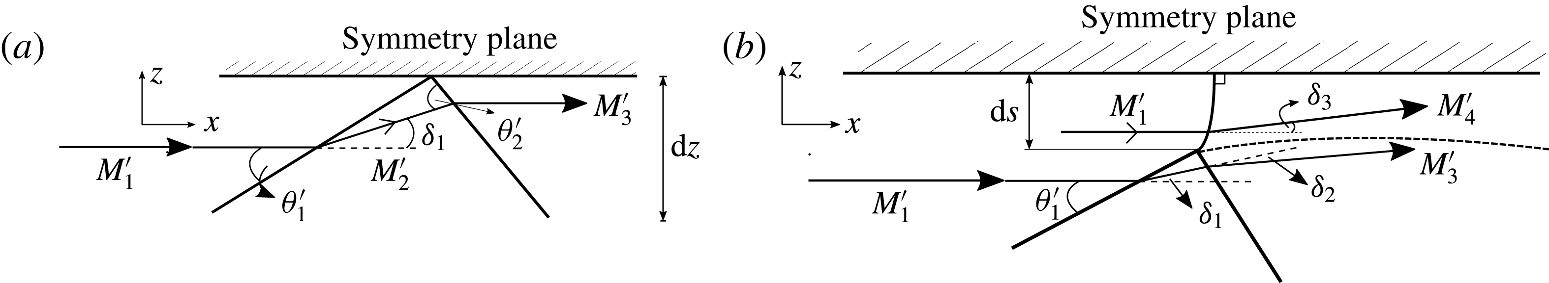
Figure 11. Schematic of analysis-plane slice of flow field on (a) RR side and (b) MR side of the transition point.
Along the entire Mach reflection portion, we consider the finite Mach stem height to be of arclength
 $\unicode[STIX]{x0394}s$
. Note that it is accepted that the Mach stem will have some variation of curvature from where it protrudes at the triple point until where it reaches the symmetry plane at its foot. At this point it is perpendicular to the symmetry plane. Specifically, at the point immediately next to the transition point T, the Mach stem height is taken to be infinitesimally small, and so the situation considered at transition is that in the limit
$\unicode[STIX]{x0394}s$
. Note that it is accepted that the Mach stem will have some variation of curvature from where it protrudes at the triple point until where it reaches the symmetry plane at its foot. At this point it is perpendicular to the symmetry plane. Specifically, at the point immediately next to the transition point T, the Mach stem height is taken to be infinitesimally small, and so the situation considered at transition is that in the limit
 $\unicode[STIX]{x0394}s\rightarrow 0$
.
$\unicode[STIX]{x0394}s\rightarrow 0$
.
Since the boundary condition of the Mach stem foot being perpendicular to the symmetry plane is still required to hold, it is reasonable to assume that the Mach stem is a normal shock in the analysis plane on the MR side of transition point T. The Mach surface just after transition is therefore modelled as a plane oblique shock relative to the oncoming flow when viewed in three-dimensional space.
The analytical procedures for resolving the flow field in figure 11 and the transition between them are now discussed. For the RR section near transition, two-shock theory is applied in the analysis plane with the boundary condition that the flow deflection across each of the shocks (incident and reflected) is identical but in an opposite sense in order to satisfy symmetry. The net flow deflection
 $\unicode[STIX]{x1D70F}_{RR}$
across the RR side of the transition point is obtained by manipulation of (2.3) and (2.6). The overall pressure ratio relating free-stream pressure to that just after the reflection point is given by
$\unicode[STIX]{x1D70F}_{RR}$
across the RR side of the transition point is obtained by manipulation of (2.3) and (2.6). The overall pressure ratio relating free-stream pressure to that just after the reflection point is given by
 $$\begin{eqnarray}\left(\frac{p_{3}}{p_{1}}\right)_{RR}=\frac{p_{3}}{p_{2}}\times \frac{p_{2}}{p_{1}},\end{eqnarray}$$
where the pressure ratio terms on the right-hand side can be generally obtained using
 $$\begin{eqnarray}\frac{p_{i+1}}{p_{i}}=1+\frac{2\unicode[STIX]{x1D712}}{\unicode[STIX]{x1D712}+1}(M_{i}^{\prime 2}\sin ^{2}\unicode[STIX]{x1D703}_{i}^{\prime }-1)\end{eqnarray}$$
for
 $i=1,2$
, where
$i=1,2$
, where
 $\unicode[STIX]{x1D712}$
is the ratio of specific heats for the fluid used (air in this case).
$\unicode[STIX]{x1D712}$
is the ratio of specific heats for the fluid used (air in this case).
For the MR portion near T, only the region at the Mach stem foot is considered. This deflects the free-stream flow by
 $$\begin{eqnarray}\tan \unicode[STIX]{x1D70F}_{MR}=2\cot \unicode[STIX]{x1D6FD}\left(\frac{M_{1}^{2}\sin ^{2}\unicode[STIX]{x1D6FD}-1}{M_{1}^{2}(\unicode[STIX]{x1D712}+\cos (2\unicode[STIX]{x1D6FD}))+2}\right).\end{eqnarray}$$
The model used here thus specifies the flow deflection through the Mach surface near the transition point as being a function of only the free-stream Mach number and the sweep angle.
The pressure ratio relating free-stream pressure with post-Mach surface pressure is obtained as
 $$\begin{eqnarray}\left(\frac{p_{4}}{p_{1}}\right)_{MR}=1+\frac{2\unicode[STIX]{x1D712}}{\unicode[STIX]{x1D712}+1}(M_{1}^{\prime 2}-1).\end{eqnarray}$$
In order for the compatibility relations about the transition point to hold for the RR and MR portions at the same sweep angle, the following conditions must be satisfied: for the flow deflection condition of (3.2),
 $$\begin{eqnarray}\unicode[STIX]{x1D6FD}-\tan ^{-1}\!\left(\frac{\cos \unicode[STIX]{x1D703}_{1}^{\prime }}{\cos (\unicode[STIX]{x1D703}_{1}^{\prime }-\unicode[STIX]{x1D6FF}_{1})}\frac{\cos \unicode[STIX]{x1D703}_{2}^{\prime }}{\cos (\unicode[STIX]{x1D703}_{2}^{\prime }-\unicode[STIX]{x1D6FF}_{1})}\tan \unicode[STIX]{x1D6FD}\right)=\tan ^{-1}\!\left(\!2\cot \unicode[STIX]{x1D6FD}\left(\frac{M_{1}^{2}\sin ^{2}\unicode[STIX]{x1D6FD}-1}{M_{1}^{2}(\unicode[STIX]{x1D712}+\cos (2\unicode[STIX]{x1D6FD}))+2}\right)\right);\end{eqnarray}$$
and for the pressure condition of (3.3),
 $$\begin{eqnarray}\left[1+\frac{2\unicode[STIX]{x1D712}}{\unicode[STIX]{x1D712}+1}(M_{2}^{2\prime }\sin ^{2}\unicode[STIX]{x1D703}_{2}^{\prime }-1)\right]\left[1+\frac{2\unicode[STIX]{x1D712}}{\unicode[STIX]{x1D712}+1}(M_{1}^{2\prime }\sin ^{2}\unicode[STIX]{x1D703}_{1}^{\prime }-1)\right]=1+\frac{2\unicode[STIX]{x1D712}}{\unicode[STIX]{x1D712}+1}(M_{1}^{2}\sin ^{2}\unicode[STIX]{x1D6FD}-1),\end{eqnarray}$$
with the pressure ratio on the regular reflection side being determined as the left-hand side of (3.9).
The results of computations for this formulation, as well as those obtained from numerical models and experiments, are discussed in the next section.
4 Results from analytical, numerical and experimental models
4.1 Results from the analytical and numerical models
It is well known that the sweepback of the three-dimensional shock system accompanies an increase in the angle of the incident shock surface relative to the oncoming flow. The effective incident shock angle
 $\unicode[STIX]{x1D703}_{1}^{\prime }$
at the detachment criterion in the analysis plane was used for sweep angles ranging from the Mach angle to
$\unicode[STIX]{x1D703}_{1}^{\prime }$
at the detachment criterion in the analysis plane was used for sweep angles ranging from the Mach angle to
 $90^{\circ }$
as
$90^{\circ }$
as
 $\unicode[STIX]{x1D6FD}\in [\sin ^{-1}(1/M_{1});90^{\circ }]$
.
$\unicode[STIX]{x1D6FD}\in [\sin ^{-1}(1/M_{1});90^{\circ }]$
.
The associated analysis-plane Mach numbers and shock angles obtained from two-shock theory at detachment are used to compute the net flow deflection
 $\unicode[STIX]{x1D70F}$
and the ratio of post-interaction and free-stream pressure for each of the regular and Mach reflection portions close to the transition point. This was plotted across the range of sweep angles, as shown in figure 12. It is worth noting that near the Mach angle (which is
$\unicode[STIX]{x1D70F}$
and the ratio of post-interaction and free-stream pressure for each of the regular and Mach reflection portions close to the transition point. This was plotted across the range of sweep angles, as shown in figure 12. It is worth noting that near the Mach angle (which is
 $19.47^{\circ }$
for
$19.47^{\circ }$
for
 $M_{1}=3.0$
) the flow deflections tend to zero, as is the case in figure 12(a), as the flow in the symmetry plane effectively passes through a Mach wave – the lower limiting case of strength of an oblique shock. Also, the pressure ratio is unity at a sweep angle equal to the Mach angle as in figure 12(b). At the opposite end of the sweep domain at
$M_{1}=3.0$
) the flow deflections tend to zero, as is the case in figure 12(a), as the flow in the symmetry plane effectively passes through a Mach wave – the lower limiting case of strength of an oblique shock. Also, the pressure ratio is unity at a sweep angle equal to the Mach angle as in figure 12(b). At the opposite end of the sweep domain at
 $\unicode[STIX]{x1D6FD}=90^{\circ }$
the net flow deflections are also zero for both RR and MR portions. In this case the situation is that of a reflection pattern which is fully equivalent to its effective analysis-plane configuration. The corresponding pressure ratios are not equal for
$\unicode[STIX]{x1D6FD}=90^{\circ }$
the net flow deflections are also zero for both RR and MR portions. In this case the situation is that of a reflection pattern which is fully equivalent to its effective analysis-plane configuration. The corresponding pressure ratios are not equal for
 $\unicode[STIX]{x1D6FD}=90^{\circ }$
, but rather the two values for the RR and MR solutions are those for two-dimensional regular reflection and one-dimensional normal shock configurations, respectively.
$\unicode[STIX]{x1D6FD}=90^{\circ }$
, but rather the two values for the RR and MR solutions are those for two-dimensional regular reflection and one-dimensional normal shock configurations, respectively.

Figure 12. (a) Net flow deflection and (b) pressure ratio at various sweep angles for RR and MR portions on either side of transition point,
 $M_{1}=3.0$
. Regular reflection solutions (dotted lines); Mach reflection solutions (solid lines).
$M_{1}=3.0$
. Regular reflection solutions (dotted lines); Mach reflection solutions (solid lines).
Both plots in figure 12 depict the important result that, for the same sweep on the RR and MR portions, the net flow deflections and pressure ratios are both not equivalent on either side of the transition point, and that this is generally the case for all transition sweep angles and all shock configurations conforming to the detachment criterion. This important result means that there must be some other physical mechanism present by which the compatibility equations can be satisfied. This is fundamental to the existence of the transition point along the intersection line. The resolution of this is based on reviewing the fundamental assumption that the sweep angle
 $\unicode[STIX]{x1D6FD}$
is common to both the RR and MR portions on either side of the transition point. If the sweep of one portion could be different from the other, there would be some leeway for the compatibility equations to be satisfied across the transition point.
$\unicode[STIX]{x1D6FD}$
is common to both the RR and MR portions on either side of the transition point. If the sweep of one portion could be different from the other, there would be some leeway for the compatibility equations to be satisfied across the transition point.
Further insights regarding the nature of the flow in the region of the transition points were obtained from examining the numerical analyses. A commercial computational fluid dynamics (CFD) package, ANSYS Fluent 17.2, was used to compute the three-dimensional flow field. The Euler equations were solved using a density-based solver and the grid was adapted during the solution to gradients of pressure, density, velocity magnitude and temperature to capture the shock structures. A review of the numerical analysis results, shown in figure 13, shows the intersection line to develop a sweep cusp at the transition point. This means that the sweep angle does not decrease monotonically along the intersection bow wave – at transition, the cusp momentarily increases the sweep, after which the sweep resumes its monotonic decrease again. Numerical results for all model geometries and for all free-stream Mach numbers (
 $M_{1}=[2.8,3.0,3.2,3.4]$
) show the existence of this cusp. Further inspection of the horizontal symmetry plane streamlines demonstrates the flow deflection compatibility across the transition point, as shown in figure 14. Another important point is the sudden change in streamline deflection before and after the transition point, resulting in a compression of the streamlines along the Mach reflection portion. The divergence of the streamlines just after transition within the Mach reflection portion is due to the increase in sweep angle of the intersection line, owing to there being a cusp at transition. The oblique shock solution to the Mach reflection portion necessitates highly deflected flow downstream of the cusp and gives rise to divergence as seen in figure 14. The deflection then reduces as does the sweep angle towards the domain periphery and this results in compression of the flow behind the Mach surface. Work is currently being done to understand the physical aspects of this, in conjunction with the trajectory of the shear layer edge which emanates from the transition point in the horizontal symmetry plane.
$M_{1}=[2.8,3.0,3.2,3.4]$
) show the existence of this cusp. Further inspection of the horizontal symmetry plane streamlines demonstrates the flow deflection compatibility across the transition point, as shown in figure 14. Another important point is the sudden change in streamline deflection before and after the transition point, resulting in a compression of the streamlines along the Mach reflection portion. The divergence of the streamlines just after transition within the Mach reflection portion is due to the increase in sweep angle of the intersection line, owing to there being a cusp at transition. The oblique shock solution to the Mach reflection portion necessitates highly deflected flow downstream of the cusp and gives rise to divergence as seen in figure 14. The deflection then reduces as does the sweep angle towards the domain periphery and this results in compression of the flow behind the Mach surface. Work is currently being done to understand the physical aspects of this, in conjunction with the trajectory of the shear layer edge which emanates from the transition point in the horizontal symmetry plane.

Figure 13. Intersection lines superimposed on density contours for (a) model 8 at
 $M_{1}=3.0$
and (b) model 10 at
$M_{1}=3.0$
and (b) model 10 at
 $M_{1}=3.0$
. (c) Model 11 Mach contours showing subsonic patches in the vicinity of transition for
$M_{1}=3.0$
. (c) Model 11 Mach contours showing subsonic patches in the vicinity of transition for
 $M_{1}=3.4$
.
$M_{1}=3.4$
.

Figure 14. Streamlines along the symmetry plane showing considerable divergence after the intersection bow wave at transition.
The ability of the three-dimensional transition model to realise the existence of the sweep cusp is now demonstrated by solving the inverse problem, this being to obtain the sweep angle for discrete segments along the intersection line given that the net flow deflection
 $\unicode[STIX]{x1D70F}$
and Mach numbers
$\unicode[STIX]{x1D70F}$
and Mach numbers
 $M_{1}$
and
$M_{1}$
and
 $M_{3}$
could be measured from the numerical results. The analysis is carried out for a case in which the sweep cusp is not immediately evident from examining the numerical model images, i.e. figure 13(a) with similar results obtained from the data of figure 13(b) and for all other test cases not shown in this paper. This was done in order to verify the capability of the analytical three-dimensional transition model to resolve gentle sweep cusps.
$M_{3}$
could be measured from the numerical results. The analysis is carried out for a case in which the sweep cusp is not immediately evident from examining the numerical model images, i.e. figure 13(a) with similar results obtained from the data of figure 13(b) and for all other test cases not shown in this paper. This was done in order to verify the capability of the analytical three-dimensional transition model to resolve gentle sweep cusps.
To arrive at a solution of the aforementioned inverse problem, the system of equations (2.3) and (2.5) was thus solved iteratively, with initial guess values of
 $\unicode[STIX]{x1D6FD}$
ranging from
$\unicode[STIX]{x1D6FD}$
ranging from
 $30^{\circ }$
to
$30^{\circ }$
to
 $90^{\circ }$
as it was clear that the sweep angle did not exceed this range for any of the cases in this work. Equivalently, one may solve for the explicit solution of the sweep angle, obtainable from (2.3) and (2.5) as
$90^{\circ }$
as it was clear that the sweep angle did not exceed this range for any of the cases in this work. Equivalently, one may solve for the explicit solution of the sweep angle, obtainable from (2.3) and (2.5) as
 $$\begin{eqnarray}\unicode[STIX]{x1D6FD}=\tan ^{-1}\!\left(\frac{{\displaystyle \frac{M_{1}}{M_{3}}}-\cos \unicode[STIX]{x1D70F}}{\sin \unicode[STIX]{x1D70F}}\right).\end{eqnarray}$$
The solutions for the sweep angle at various span stations on the intersection line for model 8 are shown in figure 15, which clearly shows the existence of the sweep cusp. The sweep angle is plotted against the
 $y$
-coordinate that has been non-dimensionalised with the half-span of the intersection bow wave. This exercise gives important evidence of the intersection line cusp for which the sweep difference is as small as approximately
$y$
-coordinate that has been non-dimensionalised with the half-span of the intersection bow wave. This exercise gives important evidence of the intersection line cusp for which the sweep difference is as small as approximately
 $1.5^{\circ }$
. More exaggerated sweep cusps are visually evident for other cases, especially so for higher free-stream Mach numbers. One such case is shown in figure 13(c), which was obtained with the highest geometry spread and highest free-stream Mach number of
$1.5^{\circ }$
. More exaggerated sweep cusps are visually evident for other cases, especially so for higher free-stream Mach numbers. One such case is shown in figure 13(c), which was obtained with the highest geometry spread and highest free-stream Mach number of
 $M_{1}=3.4$
. Here, the transition cusp was exaggerated enough to cause subsonic flow in the vicinity of the transition point. The reason for this is the large required sweep difference across the cusp, which results in the Mach reflection portion just after transition to be a strong oblique shock on the horizontal symmetry plane. The strong shock solution persists for a short distance before switching back to a weak shock solution with supersonic post-shock flow.
$M_{1}=3.4$
. Here, the transition cusp was exaggerated enough to cause subsonic flow in the vicinity of the transition point. The reason for this is the large required sweep difference across the cusp, which results in the Mach reflection portion just after transition to be a strong oblique shock on the horizontal symmetry plane. The strong shock solution persists for a short distance before switching back to a weak shock solution with supersonic post-shock flow.

Figure 15. Sweep at non-dimensionalised locations along the half-span of the intersection bow wave, as measured from figure 14.
4.2 Some experimental results
A blow-down supersonic wind tunnel was used for experimental tests with a
 $100~\text{mm}\times 100~\text{mm}$
test section. Tests were done for free-stream Mach numbers ranging from 2.8 to 3.4, with Mach-number changes being effected by a sliding nozzle block. Oblique shadow photography techniques employed to visualise the above flow fields were found to show important information regarding the swept shock configurations. This was implemented by a rotating optics gantry that enables yawed and rolled views of the flow field. A xenon flashlamp and short-exposure system was used, with a duration of approximately
$100~\text{mm}\times 100~\text{mm}$
test section. Tests were done for free-stream Mach numbers ranging from 2.8 to 3.4, with Mach-number changes being effected by a sliding nozzle block. Oblique shadow photography techniques employed to visualise the above flow fields were found to show important information regarding the swept shock configurations. This was implemented by a rotating optics gantry that enables yawed and rolled views of the flow field. A xenon flashlamp and short-exposure system was used, with a duration of approximately
 $1.5~\unicode[STIX]{x03BC}\text{s}$
to prevent image smearing due to tunnel vibrations. The angular orientation of the gantry was set at the start of each test using an inertial measurement unit (IMU) with three-axis gyroscopes and accelerometers the outputs of which were combined with a complementary filter. Yaw (denoted by
$1.5~\unicode[STIX]{x03BC}\text{s}$
to prevent image smearing due to tunnel vibrations. The angular orientation of the gantry was set at the start of each test using an inertial measurement unit (IMU) with three-axis gyroscopes and accelerometers the outputs of which were combined with a complementary filter. Yaw (denoted by
 $\unicode[STIX]{x1D706}$
) and roll (denoted by
$\unicode[STIX]{x1D706}$
) and roll (denoted by
 $\unicode[STIX]{x1D719}$
) of the optics system oriented the optical path relative to the shock system in the manner depicted in figure 16. This is useful for interpreting the images discussed subsequently in this section. In specific relation to the sweep cusps, evidence of a slight perturbation along the intersection line was noted. This is seen in figure 17 for optical orientations in both yaw and roll. Figure 17(a) shows a highly yawed point of view and the optical path passes through the Mach reflection portion on the near side of the tunnel so that it seems that there is Mach reflection in the middle. In fact, the Mach surface is viewed almost head-on along its trajectory around the intersection line. As the Mach surface is swept around the near-side portion of the flow field towards the apex of the intersection line, it decreases in height towards the downward-pointing arrow seen in the image. It is important to note that the image is foreshortened and this height decrease takes place over a much larger distance than this image depicts. The Mach surface then transitions to a regular reflection line towards the right, and this line continues further backwards along its sweep until it too transitions once more to the Mach reflection portion on the far side (right arrow). A better view of the near- and far-side transition points is shown in the zoomed and enhanced images of figure 18, which correspond to the optical orientation of figure 17(a).
$\unicode[STIX]{x1D719}$
) of the optics system oriented the optical path relative to the shock system in the manner depicted in figure 16. This is useful for interpreting the images discussed subsequently in this section. In specific relation to the sweep cusps, evidence of a slight perturbation along the intersection line was noted. This is seen in figure 17 for optical orientations in both yaw and roll. Figure 17(a) shows a highly yawed point of view and the optical path passes through the Mach reflection portion on the near side of the tunnel so that it seems that there is Mach reflection in the middle. In fact, the Mach surface is viewed almost head-on along its trajectory around the intersection line. As the Mach surface is swept around the near-side portion of the flow field towards the apex of the intersection line, it decreases in height towards the downward-pointing arrow seen in the image. It is important to note that the image is foreshortened and this height decrease takes place over a much larger distance than this image depicts. The Mach surface then transitions to a regular reflection line towards the right, and this line continues further backwards along its sweep until it too transitions once more to the Mach reflection portion on the far side (right arrow). A better view of the near- and far-side transition points is shown in the zoomed and enhanced images of figure 18, which correspond to the optical orientation of figure 17(a).

Figure 16. Orientation of optical path trajectories across density isosurfaces for model 8 at
 $M_{1}=3.0$
for yaw (
$M_{1}=3.0$
for yaw (
 $\unicode[STIX]{x1D706}$
) and roll (
$\unicode[STIX]{x1D706}$
) and roll (
 $\unicode[STIX]{x1D719}$
) orientations. Optical paths shown in red dotted lines for yaw, and in orange for roll.
$\unicode[STIX]{x1D719}$
) orientations. Optical paths shown in red dotted lines for yaw, and in orange for roll.

Figure 17. Evidence of sweep cusp from oblique shadowgraphs with yaw (
 $\unicode[STIX]{x1D706}$
) and roll (
$\unicode[STIX]{x1D706}$
) and roll (
 $\unicode[STIX]{x1D719}$
) for
$\unicode[STIX]{x1D719}$
) for
 $M_{1}=3.4$
: (a)
$M_{1}=3.4$
: (a)
 $\unicode[STIX]{x1D706}=40^{\circ }$
,
$\unicode[STIX]{x1D706}=40^{\circ }$
,
 $\unicode[STIX]{x1D719}=0^{\circ }$
; (b)
$\unicode[STIX]{x1D719}=0^{\circ }$
; (b)
 $\unicode[STIX]{x1D706}=25^{\circ }$
,
$\unicode[STIX]{x1D706}=25^{\circ }$
,
 $\unicode[STIX]{x1D719}=5^{\circ }$
.
$\unicode[STIX]{x1D719}=5^{\circ }$
.

Figure 18. Zoomed view of figure 17(a) transition points.
It is in the vicinity of the near-side transition from Mach reflection to regular reflection (left-hand side of the image) that a small bulge is seen as also shown in figure 18(a). This indicates some sort of disturbance in that region, and is attributed to the sweep cusp. Further evidence is seen in figure 17(b), which is at a lower yaw angle but with the optics system rolled by
 $5^{\circ }$
in order to slightly elevate the point of view. Here, the regular reflection portion of the intersection line is seen as the white line just above the reflected wave. As it is swept round towards the transition point on the near side (indicated by the arrow) there appears to be a slight disturbance resembling the cusp. The fact that such a feature is located at the point from which the shear surface edge emanates is further justification of experimental evidence of the sweep cusp.
$5^{\circ }$
in order to slightly elevate the point of view. Here, the regular reflection portion of the intersection line is seen as the white line just above the reflected wave. As it is swept round towards the transition point on the near side (indicated by the arrow) there appears to be a slight disturbance resembling the cusp. The fact that such a feature is located at the point from which the shear surface edge emanates is further justification of experimental evidence of the sweep cusp.
It should be noted that the cusp feature was not clear to see in the orthogonal shadowgraphs of double-wedge experiments taken by Skews (Reference Skews2000), for which edge effects were intentionally allowed to envelope the three-dimensional transition points as well as the central core regions of the flow field. However, the bulge at the near-side transition point was very clearly depicted, as shown in figure 19, which provides tentative evidence of a cusp as well.

Figure 19. Oblique shadowgraph (with
 $M_{1}=3.1$
and optical yaw
$M_{1}=3.1$
and optical yaw
 $\unicode[STIX]{x1D706}\approx 45^{\circ }$
inferred from the work of Skews (Reference Skews2000), roll
$\unicode[STIX]{x1D706}\approx 45^{\circ }$
inferred from the work of Skews (Reference Skews2000), roll
 $\unicode[STIX]{x1D719}=0^{\circ }$
) for a finite-aspect-ratio double-wedge configuration. Transition points are enveloped by edge Mach cones depicting the bulge (indicated with an arrow) at transition more dramatically than for the current results (image provided by B. W. Skews).
$\unicode[STIX]{x1D719}=0^{\circ }$
) for a finite-aspect-ratio double-wedge configuration. Transition points are enveloped by edge Mach cones depicting the bulge (indicated with an arrow) at transition more dramatically than for the current results (image provided by B. W. Skews).
5 Further aspects of three-dimensional transition
A better understanding of three-dimensional transition phenomena in the absence of edge effects is attained through the examination of the intersection line profiles and analysis-plane shock geometries. The spatial sweep variation is derived from the former, while the manner of effective shock angle variation, which governs transition in the analysis plane, is derived from the latter. Three different model geometries were tested, as shown in figure 5(a) for increasing geometrical spreads, which altered the intersection line profile and varied the shock geometry in a controlled manner to produce geometry-dependent transition conditions. Furthermore, the free-stream Mach number was varied from
 $M_{1}=2.8$
to
$M_{1}=2.8$
to
 $M_{1}=3.4$
in 0.2 increments to provide Mach-number-dependent results.
$M_{1}=3.4$
in 0.2 increments to provide Mach-number-dependent results.
There are two main reasons for paying special attention to the intersection line. Firstly, the point at which the reflection configuration undergoes transition is located on this line at the horizontal symmetry plane. It is therefore instructive to obtain the flow properties and investigate the flow physics surrounding this region on the horizontal symmetry plane before and after shock interaction. This idea was used as the basis for demonstrating the existence of the sweep cusp in the previous section, and can be further used to understand other physical aspects of transition based on the fact that it is an idealised reflecting surface. Secondly, the intersection line provides an indication as to the geometrical nature of the incident shock configurations as a whole as the intersection line sweep and overall form are similar to the rest of the incident bow wave. Having established the usefulness of considering the intersection line, its overall shape and the points of transition along it are next investigated.
5.1 Transition point locations and intersection line profiles
5.1.1 Effect of free-stream Mach number
Figure 20 shows the extracted intersection lines at the horizontal symmetry planes for model 8 at various free-stream Mach numbers. A zoomed view is also given which shows the spatial differences for each case more clearly. Also indicated are the transition points (circled) on each intersection line. It can be seen from figure 20 that higher Mach numbers weaken the incident bow wave at all locations due to the intersection lines being swept backwards and downstream to a greater extent than for the lower-Mach-number cases. This is relevant in that it is not exclusively the shock angles in the vertical planes (termed ‘actual’ shock angles here) that reduce, as was observed from the numerical data, but so do the sweep angles
 $\unicode[STIX]{x1D6FD}$
for cases with higher Mach numbers. It was found that the weaker nature of the shock surfaces (incident and reflected) for higher Mach numbers gives rise to higher compression of the flow evidenced by higher post-reflection densities for increasing free-stream Mach numbers. A similar phenomenon is noted for two-dimensional curved shocks where the free-stream flow is turned into itself by means of a curved wedge.
$\unicode[STIX]{x1D6FD}$
for cases with higher Mach numbers. It was found that the weaker nature of the shock surfaces (incident and reflected) for higher Mach numbers gives rise to higher compression of the flow evidenced by higher post-reflection densities for increasing free-stream Mach numbers. A similar phenomenon is noted for two-dimensional curved shocks where the free-stream flow is turned into itself by means of a curved wedge.

Figure 20. Effect of Mach number on extracted intersection line profiles and transition points (TP) for model 8 at
 $M_{1}=3.0$
. (a) Intersection line profiles plotted in space. (b) Zoomed-in view.
$M_{1}=3.0$
. (a) Intersection line profiles plotted in space. (b) Zoomed-in view.
The main point here is that the effect of varying the free-stream Mach number served to highlight the two modes of weakening of the shock system: by the reduction of the sweep angle
 $\unicode[STIX]{x1D6FD}$
and by the reduction of the actual shock angle
$\unicode[STIX]{x1D6FD}$
and by the reduction of the actual shock angle
 $\unicode[STIX]{x1D703}_{1}$
with an increase in the free-stream Mach number. These modes of weakening occur in the streamwise (for the former) and transverse (for the latter) directions and is unlike two-dimensional flows where only a single mode of weakening is available, this being the reduction of shock angle for higher free-stream Mach numbers.
$\unicode[STIX]{x1D703}_{1}$
with an increase in the free-stream Mach number. These modes of weakening occur in the streamwise (for the former) and transverse (for the latter) directions and is unlike two-dimensional flows where only a single mode of weakening is available, this being the reduction of shock angle for higher free-stream Mach numbers.
The dual nature of weakening of the shock system is relevant to the different locations of the transition points as seen in figure 20. The physical processes producing the effect of locating the transition points further downstream for higher Mach numbers is illustrated by figure 21, which shows the interdependences of sweep angle of the intersection line, and actual and effective shock angles. Each mode of weakening of the shock system is considered separately and in succession. As seen in figure 21, the effect of a lower shock angle for a given constant sweep angle is to obtain a reduction in the effective shock angle. If there is next a decrease in the sweep angle, this counters the previous shock angle effect and acts to increase the effective angle. It is the increase in effective angle that brings about transition. This shows the dominance of the sweep angle parameter over the shock angle in creating physical conditions that favour transition, and the variation in free-stream Mach number readily shows this. The requisite processes for increasing the shock angle are more exacerbated for lower Mach numbers and hasten the transition points to be located closer to the apex of the intersection lines as in figure 20.

Figure 21. Interdependences of actual shock angle, effective shock angle and sweep: (a) effect of sweep angle on shock angles (actual and effective); (b) effect of actual shock angle sweep and effective angles.
It is relevant to investigate the way in which the sweep profile along the intersection line may be altered and the way in which it affects the flow field. This was achieved to a limited extent by varying the free-stream Mach number. Larger variations were obtained by testing different models each with a successively wider geometrical spread, as discussed next.
5.1.2 Effect of model geometry
The increase in spread of the model geometry resulted in a wider lower-face boundary condition, as well as a flatter surface for the flow between the incident shock surface and the test piece. Investigation of shock configurations at different spreads is analogous to studying the shock surfaces obtained by an aircraft fuselage, of a similar shape to the test pieces used here, at varying altitudes. The models tested were designated as 8, 10 and 11 in order of increasing spread. Thus, a means for the controlled variation of the geometrical boundary condition, and hence intersection line sweep profile, was developed. A comparison of the various intersection line profiles and transition point locations for
 $M_{1}=3.0$
and
$M_{1}=3.0$
and
 $M_{1}=3.4$
is shown in figure 22. It is clear that the effect of a greater spread is to widen the intersection line, this effect being independent of the Mach numbers shown here. This means that the effect of increasing the spread of the lower face of the test pieces increases the spread of the incident bow wave to the extent that the spread of the intersection line is affected in the same way, thus illustrating the effect of the change in geometrical boundary condition for the flow field at the lower face of the model. Of particular interest here is the spatial location of the transition points (circled in figure 22), which are located closer to the respective intersection line apexes for increased geometrical spread. Further insight into this matter is provided by the fact that there is quite a large net deflection increase of the streamlines behind the shock interaction in the horizontal symmetry plane as the transition points are approached from the centre. This was more accentuated for model 10 (higher spread) than for model 8 (lower spread). The effect of an increase in net flow deflection through the regular intersection of shock surfaces is a decrease in the velocity ratio
$M_{1}=3.4$
is shown in figure 22. It is clear that the effect of a greater spread is to widen the intersection line, this effect being independent of the Mach numbers shown here. This means that the effect of increasing the spread of the lower face of the test pieces increases the spread of the incident bow wave to the extent that the spread of the intersection line is affected in the same way, thus illustrating the effect of the change in geometrical boundary condition for the flow field at the lower face of the model. Of particular interest here is the spatial location of the transition points (circled in figure 22), which are located closer to the respective intersection line apexes for increased geometrical spread. Further insight into this matter is provided by the fact that there is quite a large net deflection increase of the streamlines behind the shock interaction in the horizontal symmetry plane as the transition points are approached from the centre. This was more accentuated for model 10 (higher spread) than for model 8 (lower spread). The effect of an increase in net flow deflection through the regular intersection of shock surfaces is a decrease in the velocity ratio
 $R=V_{3}^{\prime }/V_{1}^{\prime }$
. This results in the decrease of the analysis-plane Mach-number ratio
$R=V_{3}^{\prime }/V_{1}^{\prime }$
. This results in the decrease of the analysis-plane Mach-number ratio
 $M_{3}^{\prime }/M_{1}^{\prime }$
and, since an effective two-shock theory analysis is valid within the analysis plane, this would mean an increase in the effective shock angle
$M_{3}^{\prime }/M_{1}^{\prime }$
and, since an effective two-shock theory analysis is valid within the analysis plane, this would mean an increase in the effective shock angle
 $\unicode[STIX]{x1D703}_{1}^{\prime }$
. This happens at an accelerated rate along the intersection line for high-spread cases compared to lower-spread ones for the same span coordinate. Since the effective angle governs transition, this is thus hastened for the high-spread cases as seen in figure 22. This explains the fact that the transition points for each case of increasing spread are located closer towards the intersection line apex.
$\unicode[STIX]{x1D703}_{1}^{\prime }$
. This happens at an accelerated rate along the intersection line for high-spread cases compared to lower-spread ones for the same span coordinate. Since the effective angle governs transition, this is thus hastened for the high-spread cases as seen in figure 22. This explains the fact that the transition points for each case of increasing spread are located closer towards the intersection line apex.

Figure 22. Comparison of intersection line profiles and transition points (TP) for various model geometrical spreads for (a)
 $M_{1}=3.0$
and (b)
$M_{1}=3.0$
and (b)
 $M_{1}=3.4$
.
$M_{1}=3.4$
.
It is thus seen how the free-stream Mach number and model geometry influence and aid in the control of three-dimensional transition. Next, the analysis of three-dimensional transition is furthered regarding its correspondence to that of two-dimensional flows.
5.2 Correspondence of transition to two-dimensional criteria
Figure 23 shows the three-dimensional transition points, as classified by sweep angle and effective shock angle, in relation to the two-dimensional transition criteria (von Neumann and detachment). All test cases carried out for this work are shown in figure 23 with results based on solutions to the numerical models. It is clear that, for low-spread model geometry, the free-stream Mach-number variation does little to significantly alter the effective Mach number at transition. This is due to the sweep profile of the intersection lines not varying much with an increase in Mach number (see figure 20 a).

Figure 23. Comparison of transition points within an
 $(M_{1}^{\prime },\unicode[STIX]{x1D703}_{1}^{\prime })$
map with two-dimensional transition criteria shown.
$(M_{1}^{\prime },\unicode[STIX]{x1D703}_{1}^{\prime })$
map with two-dimensional transition criteria shown.
It is the effective shock angle at transition that undergoes a larger change with Mach number that is more pronounced for high-spread cases. This is associated with the downstream spatial shift in transition point locations when comparing between the cases of increasing free-stream Mach number. The parameter relations examined in figure 21 in the previous section showed that it required a relatively small change in actual shock angle to effect a significant change in the effective angle for a given sweep orientation, or when comparing cases with very similar sweep profiles. Sweep angle changes could be considered not to play a major role in shifting the transition points for Mach-number variation tests, and therefore transition conditions are brought about by the rate at which the actual shock angle increases along the incident bow wave. The rate of increase of the shock angle with distance from the central regions of the flow field is a lot slower for the higher-Mach-number cases. This is due to the weakening of the incident bow wave and the location of its surface closer to the test models themselves, in the same way as a two-dimensional oblique shock is weakened in the presence of a high-Mach-number free stream. Therefore, the incident actual shock angle has to increase over a larger span distance in order for there to be conditions conducive to transition to be realised, whilst the sweep angle is reduced in such instances. This is the reason for the higher effective shock angle at transition for the cases of increased Mach number in figure 23.
The effect of an increase in geometrical spread (and thereby sweep angle) is a reduction in the effective transition angle, as seen in figure 23, such that higher-spread cases seem to have their effective transition points tend towards the two-dimensional detachment line shown. An important aspect of shock reflection is thus demonstrated through the controlled spread increase methodology used in this work. It is thus suggested that, in the absence of edge effects influencing the reflection plane, and with the opening up of the incident bow wave surface to tend towards planarity with increased geometrical spread, the shock system analysed permits transition to occur in the immediate vicinity of detachment. Following this reasoning, if the incident bow wave is spread to the extent that the spatial rate of incident wave sweep change is low enough along the transverse direction, then transition can be made to occur in the vertical mid-plane at the centre of the flow field such that Mach reflection is obtained for all portions along the horizontal symmetry plane.
Attention must be given to the physics behind the fact that the effective transition angles for the three-dimensional cases significantly exceed those governed by two-dimensional analyses (i.e. the von Neumann and detachment criteria). This was also noted for the three-dimensional studies by Skews (Reference Skews2000) in which the wedge angle (and thus effective shock angle at the vertical mid-plane) was required to be increased to
 $5^{\circ }$
above the detachment condition in order to effect transition to Mach reflection in the central region. The situation encountered here is slightly different in that transition is coupled with the sweep of the incident wave surface, which itself terminates at the reflection plane with an increasing actual shock angle as transition is approached from the regular reflection portion. This requires a closer look at the ways in which the effective angle could be increased and yet permit the incident shock to remain physically attached to the reflection plane beyond those angles predicted by effective two-dimensional theories.
$5^{\circ }$
above the detachment condition in order to effect transition to Mach reflection in the central region. The situation encountered here is slightly different in that transition is coupled with the sweep of the incident wave surface, which itself terminates at the reflection plane with an increasing actual shock angle as transition is approached from the regular reflection portion. This requires a closer look at the ways in which the effective angle could be increased and yet permit the incident shock to remain physically attached to the reflection plane beyond those angles predicted by effective two-dimensional theories.
This is accounted for by the three-dimensional relieving effect occurring within the regular reflection portion of the interaction. This means that, at transverse stations of the incident wave surface, greater transverse deflections are noted. This is attributed to the continually reducing sweep angle of the incident wave surface within the regular reflection portion of the interaction. These effects occur within horizontal planes further away from the horizontal symmetry plane and account for the curvature of the incident wave surface in a sense that reduces its shock angle at the intersection so that it remains attached at the reflecting surface beyond what is predicted by two-dimensional criteria. Along the intersection line prior to transition there is a continual reduction in sweep angle and a relatively small increase in the actual shock angle at stations further along the intersection line towards the periphery. As per (2.1) these result in an increase in the effective angle, and, as seen here, to the point of exceeding two-dimensional criteria. The discrepancy with two-dimensional theories is even more pronounced for bow wave surfaces that are further closed, as opposed to being flatter and open for high-spread and low-Mach-number cases. This is what accounts for the transition conditions for model 11 at
 $M_{1}=3.0$
to tend towards being in agreement with the two-dimensional transition criteria.
$M_{1}=3.0$
to tend towards being in agreement with the two-dimensional transition criteria.
Perhaps a clearer indication of the trends discussed and the extent to which discrepancies between three- and two-dimensional transitions are observed can be obtained from figure 24. This shows the same cases discussed in this work plotted in a non-dimensionalised axis system. The
 $x$
-axis parameter
$x$
-axis parameter
 $\unicode[STIX]{x1D702}$
is a measure of spread of the test piece, defined as the ratio of the back-face NURBS polygon to a rectangle of the same span and height, that is, the equivalent wedge geometry which corresponds to
$\unicode[STIX]{x1D702}$
is a measure of spread of the test piece, defined as the ratio of the back-face NURBS polygon to a rectangle of the same span and height, that is, the equivalent wedge geometry which corresponds to
 $\unicode[STIX]{x1D702}=1$
. The spread factor is multiplied by the Mach ratio
$\unicode[STIX]{x1D702}=1$
. The spread factor is multiplied by the Mach ratio
 $M_{1}^{\prime }/M_{1}$
, which is proportional to the sweep angle at which transition occurs and is also unity for two-dimensional transition. Importantly, the transition correspondence parameter
$M_{1}^{\prime }/M_{1}$
, which is proportional to the sweep angle at which transition occurs and is also unity for two-dimensional transition. Importantly, the transition correspondence parameter
 $\unicode[STIX]{x1D702}(M_{1}^{\prime }/M_{1})$
is transformed to be unity for the two-dimensional transition criteria. This means that any departure from unity of the transition correspondence parameter indicates three-dimensional flow. For such cases, the extent to which the transition correspondence parameter approaches unity is associated with the extent to which three-dimensional transition corresponds to that of two-dimensional flows. The
$\unicode[STIX]{x1D702}(M_{1}^{\prime }/M_{1})$
is transformed to be unity for the two-dimensional transition criteria. This means that any departure from unity of the transition correspondence parameter indicates three-dimensional flow. For such cases, the extent to which the transition correspondence parameter approaches unity is associated with the extent to which three-dimensional transition corresponds to that of two-dimensional flows. The
 $y$
-axis was chosen to contain the ratio of the effective shock angle at transition to the sweep angle at transition (
$y$
-axis was chosen to contain the ratio of the effective shock angle at transition to the sweep angle at transition (
 $\unicode[STIX]{x1D6FD}_{tr}$
). It is expected that sweep angle at which transition occurs would increase for cases approaching conditions of two-dimensional transition, and the effective flow parameter
$\unicode[STIX]{x1D6FD}_{tr}$
). It is expected that sweep angle at which transition occurs would increase for cases approaching conditions of two-dimensional transition, and the effective flow parameter
 $\unicode[STIX]{x1D703}_{1}^{\prime }/\unicode[STIX]{x1D6FD}_{tr}$
reflects this. Figure 24 clearly shows the effect of Mach-number and geometry variation on the extents to which the three-dimensional transition cases studied here differ from two-dimensional criteria.
$\unicode[STIX]{x1D703}_{1}^{\prime }/\unicode[STIX]{x1D6FD}_{tr}$
reflects this. Figure 24 clearly shows the effect of Mach-number and geometry variation on the extents to which the three-dimensional transition cases studied here differ from two-dimensional criteria.

Figure 24. Non-dimensionalisation of figure 23. Two-dimensional transition has a correspondence parameter of unity.
6 Conclusions
An investigation on shock reflection transition has been conducted on three-dimensional supersonic flow fields in the absence of edge effects influencing transition. The analytical model of the shock configuration on both sides of the transition point indicated the presence of a sweep cusp in order that the compatibility conditions across transition be satisfied. The numerical models provide evidence of such cusps on the line of intersection of the incident shock surface with the horizontal symmetry plane. This has been verified by solving the inverse problem with the suggested model to compute the intersection line sweep. Further evidence is provided by experimental oblique shadowgraphs, which indicate a bulge at the transition points indicative of the sweep cusp. It was found that this corresponds to images from double-wedge flows in which the transition points are enveloped by edge Mach cones, which provides tentative evidence of the cusp in such cases.
Further investigation involved elucidating the effect of geometry and free-stream Mach-number variation on the shock topology and transition point location. It was found that considerable variations occur for geometry variation tests, whilst the changes in Mach number served to highlight the physical processes and dual nature of weakening of the three-dimensional shock system.
Finally, consideration was given to the correspondence of the three-dimensional effective transition angles to those suggested by two-dimensional criteria. The three-dimensional transition points considerably exceed those of two-dimensional criteria and this is attributed to the relieving effect which reduces the shock incidence yet keeps it attached to the reflecting surface. Wider spreads and lower free-stream Mach numbers return three-dimensional transition points that tend towards agreement with two-dimensional theories.