


1 Introduction
Dry granular flows down a solid surface at an inclination angle
 $\unicode[STIX]{x1D703}$
have been extensively studied due to their frequent appearance in industrial processes,
$\unicode[STIX]{x1D703}$
have been extensively studied due to their frequent appearance in industrial processes,
 $\!$
geophysical events and rheology tests. Under the action of gravity, constituent grains move towards the base into a dense configuration with multiple enduring contacts so that the flow is often dense and frictional in nature. For a continuous steady dense flow of uniform thickness, experiments and numerical simulations have revealed a minimum flow depth,
$\!$
geophysical events and rheology tests. Under the action of gravity, constituent grains move towards the base into a dense configuration with multiple enduring contacts so that the flow is often dense and frictional in nature. For a continuous steady dense flow of uniform thickness, experiments and numerical simulations have revealed a minimum flow depth,
 $h_{stop}$
, below which the flow stops en masse. This critical thickness is a function of
$h_{stop}$
, below which the flow stops en masse. This critical thickness is a function of
 $\unicode[STIX]{x1D703}$
,
$\unicode[STIX]{x1D703}$
,
 $h_{stop}(\unicode[STIX]{x1D703})$
, that diverges at a lower threshold,
$h_{stop}(\unicode[STIX]{x1D703})$
, that diverges at a lower threshold,
 $\unicode[STIX]{x1D703}_{1}$
, and diminishes monotonically to zero at an upper limit,
$\unicode[STIX]{x1D703}_{1}$
, and diminishes monotonically to zero at an upper limit,
 $\unicode[STIX]{x1D703}_{2}$
(Daerr & Douady Reference Daerr and Douady1999; Pouliquen Reference Pouliquen1999; Silbert, Landry & Grest Reference Silbert, Landry and Grest2003; GDRMidi 2004; Borzsonyi, Halsey & Ecke Reference Borzsonyi, Halsey and Ecke2008; Staron Reference Staron2008). These findings suggest a complex rheological behaviour regarding the manner in which a moving bulk halts upon changes of flow condition. On the other hand, the motion of a finite granular mass is often unsteady, non-uniform and exhibits a finite run-out distance and flow arrest time. For example, Pouliquen & Forterre (Reference Pouliquen and Forterre2002) released finite glass beads down a roughened bed and observed a flow-to-no-flow arresting transition that first developed at the rear and moved towards the front so that the whole bulk formed a solid deposit in a certain period. Similar to most gravity-driven flows, granular incline flows often propagate in a shallow configuration and the small height-to-length aspect ratio can be exploited together with the dense nature of the flow to simplify the conservation equations of mass and momentum into an incompressible shallow flow model. The resulting equations govern the flow depth and depth-averaged streamwise velocity with a phenomenological model for basal friction (Savage & Hutter Reference Savage and Hutter1989; Daerr Reference Daerr2001; Pouliquen & Forterre Reference Pouliquen and Forterre2002; Hogg Reference Hogg2007). In addition, the influence of fluid-to-solid transition on bulk dynamics has also been accounted for by incorporating a deposition scheme in terms of flow depth and internal friction angle (Bouchaud et al.
Reference Bouchaud, Cates, Prakash and Edwards1994), or with further dependence on transition interface velocity (Boutreux, Raphael & de Gennes Reference Boutreux, Raphael and de Gennes1998; Tai & Kuo Reference Tai and Kuo2008; Gray & Ancey Reference Gray and Ancey2009). Owing to the flow-dependent basal friction and deposition scheme, a numerical solution is often required and has been shown to reproduce many flow features observed in laboratory experiments of an inclined flows (Mangeney-Castelnau et al.
Reference Mangeney-Castelnau, Roche, Hungr, Mangold, Faccanoni and Lucas2010) or flows due to a column collapse (Balmforth & Kerswell Reference Balmforth and Kerswell2005; Mangeney-Castelnau et al.
Reference Mangeney-Castelnau, Bouchut, Vilotte, Lajeunesse, Aubertin and Pirulli2005).
$\unicode[STIX]{x1D703}_{2}$
(Daerr & Douady Reference Daerr and Douady1999; Pouliquen Reference Pouliquen1999; Silbert, Landry & Grest Reference Silbert, Landry and Grest2003; GDRMidi 2004; Borzsonyi, Halsey & Ecke Reference Borzsonyi, Halsey and Ecke2008; Staron Reference Staron2008). These findings suggest a complex rheological behaviour regarding the manner in which a moving bulk halts upon changes of flow condition. On the other hand, the motion of a finite granular mass is often unsteady, non-uniform and exhibits a finite run-out distance and flow arrest time. For example, Pouliquen & Forterre (Reference Pouliquen and Forterre2002) released finite glass beads down a roughened bed and observed a flow-to-no-flow arresting transition that first developed at the rear and moved towards the front so that the whole bulk formed a solid deposit in a certain period. Similar to most gravity-driven flows, granular incline flows often propagate in a shallow configuration and the small height-to-length aspect ratio can be exploited together with the dense nature of the flow to simplify the conservation equations of mass and momentum into an incompressible shallow flow model. The resulting equations govern the flow depth and depth-averaged streamwise velocity with a phenomenological model for basal friction (Savage & Hutter Reference Savage and Hutter1989; Daerr Reference Daerr2001; Pouliquen & Forterre Reference Pouliquen and Forterre2002; Hogg Reference Hogg2007). In addition, the influence of fluid-to-solid transition on bulk dynamics has also been accounted for by incorporating a deposition scheme in terms of flow depth and internal friction angle (Bouchaud et al.
Reference Bouchaud, Cates, Prakash and Edwards1994), or with further dependence on transition interface velocity (Boutreux, Raphael & de Gennes Reference Boutreux, Raphael and de Gennes1998; Tai & Kuo Reference Tai and Kuo2008; Gray & Ancey Reference Gray and Ancey2009). Owing to the flow-dependent basal friction and deposition scheme, a numerical solution is often required and has been shown to reproduce many flow features observed in laboratory experiments of an inclined flows (Mangeney-Castelnau et al.
Reference Mangeney-Castelnau, Roche, Hungr, Mangold, Faccanoni and Lucas2010) or flows due to a column collapse (Balmforth & Kerswell Reference Balmforth and Kerswell2005; Mangeney-Castelnau et al.
Reference Mangeney-Castelnau, Bouchut, Vilotte, Lajeunesse, Aubertin and Pirulli2005).
Such a feasible simplification via depth averaging, nonetheless, causes information loss in the method for how a fluid–solid interface may develop across a layer during the deposition process, consequently necessitating further modelling efforts. A two-dimensional non-depth-averaged Coulomb–viscoplastic sliding law with pressure and rate dependence has been proposed and integrated to a shallow flow model so that the temporal and spatial evolution of a solid–liquid interface can be numerically solved (Domnik & Pudasaini Reference Domnik and Pudasaini2012; Domnik et al.
Reference Domnik, Pudasaini, Katzenbach and Miller2013). Different theories have also been proposed to address the
 $h_{stop}$
phenomenon for a continuous steady flow with a uniform thickness. Kinetic theory of a dense gas has been employed to show that solid phase develops when the fluctuation energy generated by particle collisions is insufficient to compensate for the energy dissipated due to inelastic or frictional contact (Louge Reference Louge2003; Jenkins Reference Jenkins2006; Kumaran Reference Kumaran2008). In the non-local self-activation theory (Pouliquen & Forterre Reference Pouliquen and Forterre2009), a flow coming to a halt is explained by grain-level local avalanche events in a thin layer being too rare to self-trigger a continuous flow. Another class of models based on the Ginzburg–Landau phase transition theory, which introduces an order parameter to describe the extent of fluidization of a bulk, can also reproduce the
$h_{stop}$
phenomenon for a continuous steady flow with a uniform thickness. Kinetic theory of a dense gas has been employed to show that solid phase develops when the fluctuation energy generated by particle collisions is insufficient to compensate for the energy dissipated due to inelastic or frictional contact (Louge Reference Louge2003; Jenkins Reference Jenkins2006; Kumaran Reference Kumaran2008). In the non-local self-activation theory (Pouliquen & Forterre Reference Pouliquen and Forterre2009), a flow coming to a halt is explained by grain-level local avalanche events in a thin layer being too rare to self-trigger a continuous flow. Another class of models based on the Ginzburg–Landau phase transition theory, which introduces an order parameter to describe the extent of fluidization of a bulk, can also reproduce the
 $h_{stop}$
phenomenon (Aranson & Tsimring Reference Aranson and Tsimring2002; Kamrin & Henann Reference Kamrin and Henann2015).
$h_{stop}$
phenomenon (Aranson & Tsimring Reference Aranson and Tsimring2002; Kamrin & Henann Reference Kamrin and Henann2015).
Nonetheless, it is noted that the
 $h_{stop}$
phenomenon is first captured by the coherence length model developed by Ertas & Halsey (Reference Ertas and Halsey2002) considering how bulk dynamics depends on the spatial correlation between grains over a length scale of
$h_{stop}$
phenomenon is first captured by the coherence length model developed by Ertas & Halsey (Reference Ertas and Halsey2002) considering how bulk dynamics depends on the spatial correlation between grains over a length scale of
 $l$
owing to their multiple enduring contacts. This coherence length
$l$
owing to their multiple enduring contacts. This coherence length
 $l$
should evolve with the flow and the authors match the time scale of growth by inelastic interaction between grains,
$l$
should evolve with the flow and the authors match the time scale of growth by inelastic interaction between grains,
 $(l|\unicode[STIX]{x2202}_{y}u|/g)f(e)$
, to that of destruction,
$(l|\unicode[STIX]{x2202}_{y}u|/g)f(e)$
, to that of destruction,
 $(l|\unicode[STIX]{x2202}_{yy}u|)^{-1}$
, when the motions of those spatially correlated grains are no longer compatible with bulk shear. A dynamic equation for
$(l|\unicode[STIX]{x2202}_{yy}u|)^{-1}$
, when the motions of those spatially correlated grains are no longer compatible with bulk shear. A dynamic equation for
 $l$
is then formulated as
$l$
is then formulated as
 $$\begin{eqnarray}l^{2}\left|\frac{\unicode[STIX]{x2202}}{\unicode[STIX]{x2202}y}\left[\left(\frac{\unicode[STIX]{x2202}u}{\unicode[STIX]{x2202}y}\right)^{2}\right]\right|=\hat{a}gf(e),\end{eqnarray}$$
where
 $u(y)$
is the downslope velocity profile, with
$u(y)$
is the downslope velocity profile, with
 $y$
measuring the perpendicular distance to the base,
$y$
measuring the perpendicular distance to the base,
 $g$
represents gravity,
$g$
represents gravity,
 $f(e)=(1-e)/e$
is a proposed function that decreases monotonically with the grain coefficient of restitution,
$f(e)=(1-e)/e$
is a proposed function that decreases monotonically with the grain coefficient of restitution,
 $e$
, and
$e$
, and
 $\hat{a}$
is a constant of order unity. When
$\hat{a}$
is a constant of order unity. When
 $l$
is sufficiently smaller than the flow height, momentum transport across a viscous transport length
$l$
is sufficiently smaller than the flow height, momentum transport across a viscous transport length
 $l_{v}$
, which is associated with
$l_{v}$
, which is associated with
 $l$
, during a shear time
$l$
, during a shear time
 $(\unicode[STIX]{x2202}_{y}u)^{-1}$
can result in a stress as
$(\unicode[STIX]{x2202}_{y}u)^{-1}$
can result in a stress as
 $$\begin{eqnarray}\unicode[STIX]{x1D70F}=\unicode[STIX]{x1D70C}l_{v}^{2}\left(\frac{\unicode[STIX]{x2202}u}{\unicode[STIX]{x2202}y}\right)^{2}.\end{eqnarray}$$
This is formulated following the concept of how eddy-induced stress in turbulent flows is modelled in Prandtl’s mixing-length theory. Since the viscous transport length should approach a grain diameter
 $D$
to recover the Bagnold stress
$D$
to recover the Bagnold stress
 $\unicode[STIX]{x1D70C}D^{2}(\unicode[STIX]{x2202}_{y}u)^{2}$
(Bagnold Reference Bagnold1954) in the rapid collisional regime where the correlation between grains diminishes, Ertas & Halsey (Reference Ertas and Halsey2002) proposed the following asymptotic relation:
$\unicode[STIX]{x1D70C}D^{2}(\unicode[STIX]{x2202}_{y}u)^{2}$
(Bagnold Reference Bagnold1954) in the rapid collisional regime where the correlation between grains diminishes, Ertas & Halsey (Reference Ertas and Halsey2002) proposed the following asymptotic relation:
 $$\begin{eqnarray}l_{v}^{2}=l^{2}\left(1+\hat{b}\frac{D}{l}+\cdots \,\right),\end{eqnarray}$$
where
 $\hat{b}$
represents a constant accounting for the first-order correction of such a finite-size effect. Although this constitutive relation is developed via scaling arguments, Ertas & Halsey (Reference Ertas and Halsey2002) demonstrated that its application to steady uniform-thickness flows can qualitatively capture the Bagnold velocity profile (GDRMidi 2004) and Pouliquen’s flow rule (Pouliquen Reference Pouliquen1999). In particular, the coherence length is solved to be
$\hat{b}$
represents a constant accounting for the first-order correction of such a finite-size effect. Although this constitutive relation is developed via scaling arguments, Ertas & Halsey (Reference Ertas and Halsey2002) demonstrated that its application to steady uniform-thickness flows can qualitatively capture the Bagnold velocity profile (GDRMidi 2004) and Pouliquen’s flow rule (Pouliquen Reference Pouliquen1999). In particular, the coherence length is solved to be
 $l\sim D/[\sin \unicode[STIX]{x1D703}-\sin \unicode[STIX]{x1D703}_{r}(e)]$
, which qualitatively captures the monotonically increasing
$l\sim D/[\sin \unicode[STIX]{x1D703}-\sin \unicode[STIX]{x1D703}_{r}(e)]$
, which qualitatively captures the monotonically increasing
 $h_{stop}(\unicode[STIX]{x1D703})$
when
$h_{stop}(\unicode[STIX]{x1D703})$
when
 $l(\unicode[STIX]{x1D703})$
in a decelerating bulk approaches the flow thickness as
$l(\unicode[STIX]{x1D703})$
in a decelerating bulk approaches the flow thickness as
 $\unicode[STIX]{x1D703}$
is diminished towards the predicted repose angle
$\unicode[STIX]{x1D703}$
is diminished towards the predicted repose angle
 $\unicode[STIX]{x1D703}_{r}(e)=\sin ^{-1}[\hat{a}f(e)]$
corresponding to the measured angle
$\unicode[STIX]{x1D703}_{r}(e)=\sin ^{-1}[\hat{a}f(e)]$
corresponding to the measured angle
 $\unicode[STIX]{x1D703}_{1}$
(Ertas & Halsey Reference Ertas and Halsey2002). The speculated correspondence between
$\unicode[STIX]{x1D703}_{1}$
(Ertas & Halsey Reference Ertas and Halsey2002). The speculated correspondence between
 $h_{stop}$
and spatially correlated grain motions has been evidenced in experiments (Pouliquen Reference Pouliquen2004) and numerical simulations (Baran et al.
Reference Baran, Ertaş, Halsey, Grest and Lechman2006; Staron Reference Staron2008). Even more encouraging, the concept of coherence length has also been integrated with the well-accepted
$h_{stop}$
and spatially correlated grain motions has been evidenced in experiments (Pouliquen Reference Pouliquen2004) and numerical simulations (Baran et al.
Reference Baran, Ertaş, Halsey, Grest and Lechman2006; Staron Reference Staron2008). Even more encouraging, the concept of coherence length has also been integrated with the well-accepted
 $\unicode[STIX]{x1D707}(I)$
constitutive relation for shear stress for a gentle slope with smooth particles so that the
$\unicode[STIX]{x1D707}(I)$
constitutive relation for shear stress for a gentle slope with smooth particles so that the
 $h_{stop}(\unicode[STIX]{x1D703})$
function can be analytically solved for steady uniform flows by simply replacing
$h_{stop}(\unicode[STIX]{x1D703})$
function can be analytically solved for steady uniform flows by simply replacing
 $\unicode[STIX]{x1D70F}$
in (1.2) (GDRMidi 2004).
$\unicode[STIX]{x1D70F}$
in (1.2) (GDRMidi 2004).
Hence, this work attempts to apply the coherence length model for the propagation of finite granular mass down a straight rough incline to examine whether the finite run-out distance and arrest time can be captured. This will test if the fluid-to-solid transition across the layer can be effectively inferred by the associated arresting mechanism, which is the primary objective of this work. The second aim is to formulate a theoretical framework on which analytical solutions may be sought to complement the findings from experiments and the numerical solution to a depth-averaged shallow layer model. We focus on the dynamics of a shallow layer in the long run-out down a mild incline so that the influences of initial condition and bulk inertia may be negligible and the small aspect ratio permits asymptotic solutions. The governing equations are formulated in § 2 and the asymptotic flow solutions are derived in § 3 at a fully flowing state (with
 $l\ll h$
) and exploited to estimate how
$l\ll h$
) and exploited to estimate how
 $l$
grows in the flow. A dynamic model is developed to describe how the front of a solid deposition wave propagates downstream in § 4, which is further modified to correct the errors in assuming that the propagation dynamics is decoupled from the deposition process. The final model is then evaluated by comparing the predictions of a transient front trajectory at
$l$
grows in the flow. A dynamic model is developed to describe how the front of a solid deposition wave propagates downstream in § 4, which is further modified to correct the errors in assuming that the propagation dynamics is decoupled from the deposition process. The final model is then evaluated by comparing the predictions of a transient front trajectory at
 $\unicode[STIX]{x1D703}=23^{\circ }$
and the final run-out distances on different slopes to those measured by Pouliquen & Forterre (Reference Pouliquen and Forterre2002). Finally, a summary and discussions on the limitations of the current analysis are given in § 5.
$\unicode[STIX]{x1D703}=23^{\circ }$
and the final run-out distances on different slopes to those measured by Pouliquen & Forterre (Reference Pouliquen and Forterre2002). Finally, a summary and discussions on the limitations of the current analysis are given in § 5.

Figure 1. Illustration and nomenclature of the problem. The black solid and dashed lines depict possible surface profiles of the flow and solid deposit, while an initial packing is shown by the grey solid line. The symbol
 $h(x,t)$
represents the instantaneous flow surface,
$h(x,t)$
represents the instantaneous flow surface,
 $x_{f}(t)$
the location of the flow front, and
$x_{f}(t)$
the location of the flow front, and
 $x_{d}(t)$
and
$x_{d}(t)$
and
 $h_{d}(t)$
represent the location and surface height at the deposit front, respectively. The local coherence length among spatially correlated grains is
$h_{d}(t)$
represent the location and surface height at the deposit front, respectively. The local coherence length among spatially correlated grains is
 $l$
. An undetermined solid–liquid interface depth profile is presented by both the concave and convex dashed lines.
$l$
. An undetermined solid–liquid interface depth profile is presented by both the concave and convex dashed lines.
2 Governing equations
2.1 Problem description
Consider a two-dimensional granular material of total mass
 $M$
being released down a rough incline at a mild angle
$M$
being released down a rough incline at a mild angle
 $\unicode[STIX]{x1D703}$
from the horizontal as shown in figure 1. A Cartesian coordinate system
$\unicode[STIX]{x1D703}$
from the horizontal as shown in figure 1. A Cartesian coordinate system
 $Oxy$
is defined at the rear end of the mass upon initiation, with
$Oxy$
is defined at the rear end of the mass upon initiation, with
 $x$
and
$x$
and
 $y$
being the downslope and the slope-normal coordinates, respectively. The corresponding velocity components are
$y$
being the downslope and the slope-normal coordinates, respectively. The corresponding velocity components are
 $u(x,y,t)$
and
$u(x,y,t)$
and
 $v(x,y,t)$
, the free-surface profile normal to the base is
$v(x,y,t)$
, the free-surface profile normal to the base is
 $h(x,t)$
, and the location of the flow front is
$h(x,t)$
, and the location of the flow front is
 $x_{f}(t)$
. From experimental observations, a static deposit may form in the rear and a flow-to-no-flow transition occurs midstream to create a fluid–solid interface that moves downstream. When the interface eventually reaches the flow front, the entire mass stops at finite run-out distance of
$x_{f}(t)$
. From experimental observations, a static deposit may form in the rear and a flow-to-no-flow transition occurs midstream to create a fluid–solid interface that moves downstream. When the interface eventually reaches the flow front, the entire mass stops at finite run-out distance of
 $L_{d}$
and arrest time
$L_{d}$
and arrest time
 $T_{d}$
(Pouliquen & Forterre Reference Pouliquen and Forterre2002). Here, we use the coherence length model developed by Ertas & Halsey (Reference Ertas and Halsey2002) and their arresting mechanism to determine if these observed flow features may be reproduced analytically.
$T_{d}$
(Pouliquen & Forterre Reference Pouliquen and Forterre2002). Here, we use the coherence length model developed by Ertas & Halsey (Reference Ertas and Halsey2002) and their arresting mechanism to determine if these observed flow features may be reproduced analytically.
2.2 Model formulation
When the flow coherence length is sufficiently small,
 $\!$
bulk motion may be
$\!$
bulk motion may be
 $\!$
approximated by a shallow, isotropic and incompressible flow with a constant bulk density
$\!$
approximated by a shallow, isotropic and incompressible flow with a constant bulk density
 $\unicode[STIX]{x1D70C}$
(Pudasaini & Hutter Reference Pudasaini and Hutter2007; Andreotti, Forterre & Pouliquen Reference Andreotti, Forterre and Pouliquen2013). The conservation equations of mass and momentum are
$\unicode[STIX]{x1D70C}$
(Pudasaini & Hutter Reference Pudasaini and Hutter2007; Andreotti, Forterre & Pouliquen Reference Andreotti, Forterre and Pouliquen2013). The conservation equations of mass and momentum are
 $$\begin{eqnarray}\displaystyle & \displaystyle \frac{\unicode[STIX]{x2202}u}{\unicode[STIX]{x2202}x}+\frac{\unicode[STIX]{x2202}v}{\unicode[STIX]{x2202}y}=0, & \displaystyle\end{eqnarray}$$
 $$\begin{eqnarray}\displaystyle & \displaystyle \unicode[STIX]{x1D70C}\left(\frac{\unicode[STIX]{x2202}u}{\unicode[STIX]{x2202}t}+u\frac{\unicode[STIX]{x2202}u}{\unicode[STIX]{x2202}x}+v\frac{\unicode[STIX]{x2202}u}{\unicode[STIX]{x2202}y}\right)=\frac{\unicode[STIX]{x2202}\unicode[STIX]{x1D70E}_{xx}}{\unicode[STIX]{x2202}x}+\frac{\unicode[STIX]{x2202}\unicode[STIX]{x1D70E}_{yx}}{\unicode[STIX]{x2202}y}+\unicode[STIX]{x1D70C}g\sin \unicode[STIX]{x1D703}, & \displaystyle\end{eqnarray}$$
 $$\begin{eqnarray}\displaystyle & \displaystyle 0=\frac{\unicode[STIX]{x2202}\unicode[STIX]{x1D70E}_{yy}}{\unicode[STIX]{x2202}y}-\unicode[STIX]{x1D70C}g\cos \unicode[STIX]{x1D703}. & \displaystyle\end{eqnarray}$$
The
 $y$
-momentum equation in (2.3) has been simplified, under the condition of flow shallowness, into a balance between the gradient of the normal stress component and the
$y$
-momentum equation in (2.3) has been simplified, under the condition of flow shallowness, into a balance between the gradient of the normal stress component and the
 $y$
-component of gravity (Pudasaini & Hutter Reference Pudasaini and Hutter2007; Andreotti et al.
Reference Andreotti, Forterre and Pouliquen2013). The assumption of flow isotropy gives
$y$
-component of gravity (Pudasaini & Hutter Reference Pudasaini and Hutter2007; Andreotti et al.
Reference Andreotti, Forterre and Pouliquen2013). The assumption of flow isotropy gives
 $\unicode[STIX]{x1D70E}_{xx}=\unicode[STIX]{x1D70E}_{yy}$
and the shear component,
$\unicode[STIX]{x1D70E}_{xx}=\unicode[STIX]{x1D70E}_{yy}$
and the shear component,
 $\unicode[STIX]{x1D70E}_{yx}$
, is described by the coherence length model using (1.1)–(1.3). These governing equations are subject to stress-free and kinematic conditions on the free surface,
$\unicode[STIX]{x1D70E}_{yx}$
, is described by the coherence length model using (1.1)–(1.3). These governing equations are subject to stress-free and kinematic conditions on the free surface,
 $$\begin{eqnarray}\displaystyle & \displaystyle \unicode[STIX]{x1D70E}_{xx}=\unicode[STIX]{x1D70E}_{yy}=\unicode[STIX]{x1D70E}_{yx}=0,\quad \text{at }y=h(x,t), & \displaystyle\end{eqnarray}$$
 $$\begin{eqnarray}\displaystyle & \displaystyle \frac{\unicode[STIX]{x2202}h}{\unicode[STIX]{x2202}t}+u\frac{\unicode[STIX]{x2202}h}{\unicode[STIX]{x2202}x}-v=0,\quad \text{at }y=h(x,t), & \displaystyle\end{eqnarray}$$
and to no-penetration and no-slip boundary conditions at the base,
 $$\begin{eqnarray}\displaystyle & \displaystyle v=0,\quad \text{at }y=0, & \displaystyle\end{eqnarray}$$
 $$\begin{eqnarray}\displaystyle & \displaystyle u=0,\quad \text{at }y=0. & \displaystyle\end{eqnarray}$$
Flow variables are non-dimensionalized by characteristic flow height and length,
 $H$
and
$H$
and
 $L$
, downstream flow speed,
$L$
, downstream flow speed,
 $U$
, and bulk density,
$U$
, and bulk density,
 $\unicode[STIX]{x1D70C}$
, into
$\unicode[STIX]{x1D70C}$
, into
 $$\begin{eqnarray}\displaystyle \left.\begin{array}{@{}c@{}}\displaystyle \left(x,y,h,x_{d},h_{d},L_{d},l,l_{v},D\right)=L(\tilde{x},\unicode[STIX]{x1D716}{\tilde{y}},\unicode[STIX]{x1D716}\tilde{h},\tilde{x}_{d},\unicode[STIX]{x1D716}\tilde{h}_{d},\tilde{L}_{d},\unicode[STIX]{x1D716}\tilde{l},\unicode[STIX]{x1D716}\tilde{l}_{v},\unicode[STIX]{x1D716}\tilde{D}),\\ \displaystyle (u,v)=U(\tilde{u} ,\unicode[STIX]{x1D716}\tilde{v}),\quad (t,T_{d})=(L/U)(\tilde{t},\tilde{T}_{d}),\quad \unicode[STIX]{x1D70E}_{yx}=\unicode[STIX]{x1D70C}U^{2}\tilde{\unicode[STIX]{x1D70E}}_{yx},\quad M=\unicode[STIX]{x1D70C}HL\tilde{M},\end{array}\right\} & & \displaystyle\end{eqnarray}$$
with a small flow aspect ratio,
 $\unicode[STIX]{x1D716}\equiv H/L\ll 1$
. Flow Froude number,
$\unicode[STIX]{x1D716}\equiv H/L\ll 1$
. Flow Froude number,
 $Fr\equiv U/\sqrt{gH}$
, is defined consistently as that used by Ertas & Halsey (Reference Ertas and Halsey2002) on uniform flows and by Pouliquen & Forterre (Reference Pouliquen and Forterre2002), whose experimental results are adopted later to evaluate our model. We have also worked with the conventional and extended Froude number with reduced gravity,
$Fr\equiv U/\sqrt{gH}$
, is defined consistently as that used by Ertas & Halsey (Reference Ertas and Halsey2002) on uniform flows and by Pouliquen & Forterre (Reference Pouliquen and Forterre2002), whose experimental results are adopted later to evaluate our model. We have also worked with the conventional and extended Froude number with reduced gravity,
 $\sqrt{gH\cos \unicode[STIX]{x1D703}}$
(Borzsonyi et al.
Reference Borzsonyi, Halsey and Ecke2008; Domnik et al.
Reference Domnik, Pudasaini, Katzenbach and Miller2013; Edwards & Gray Reference Edwards and Gray2014), so that the resulting equations and the corresponding asymptotic solutions possess complex coefficients with multiple appearances of
$\sqrt{gH\cos \unicode[STIX]{x1D703}}$
(Borzsonyi et al.
Reference Borzsonyi, Halsey and Ecke2008; Domnik et al.
Reference Domnik, Pudasaini, Katzenbach and Miller2013; Edwards & Gray Reference Edwards and Gray2014), so that the resulting equations and the corresponding asymptotic solutions possess complex coefficients with multiple appearances of
 $\cos \unicode[STIX]{x1D703}$
. Since
$\cos \unicode[STIX]{x1D703}$
. Since
 $\cos \unicode[STIX]{x1D703}$
is of order unity on milder slopes, removing
$\cos \unicode[STIX]{x1D703}$
is of order unity on milder slopes, removing
 $\cos \unicode[STIX]{x1D703}$
from these coefficients does not change the nature of the equations, which supports the current
$\cos \unicode[STIX]{x1D703}$
from these coefficients does not change the nature of the equations, which supports the current
 $Fr$
. The dimensionless continuity and
$Fr$
. The dimensionless continuity and
 $x$
-momentum equation become
$x$
-momentum equation become
 $$\begin{eqnarray}\displaystyle & \displaystyle \frac{\unicode[STIX]{x2202}\tilde{u} }{\unicode[STIX]{x2202}\tilde{x}}+\frac{\unicode[STIX]{x2202}\tilde{v}}{\unicode[STIX]{x2202}{\tilde{y}}}=0, & \displaystyle\end{eqnarray}$$
 $$\begin{eqnarray}\displaystyle & \displaystyle \unicode[STIX]{x1D716}Fr^{2}\left(\frac{\unicode[STIX]{x2202}\tilde{u} }{\unicode[STIX]{x2202}\tilde{t}}+\tilde{u} \frac{\unicode[STIX]{x2202}\tilde{u} }{\unicode[STIX]{x2202}\tilde{x}}+\tilde{v}\frac{\unicode[STIX]{x2202}\tilde{u} }{\unicode[STIX]{x2202}{\tilde{y}}}\right)=\unicode[STIX]{x1D716}\cos \unicode[STIX]{x1D703}\frac{\unicode[STIX]{x2202}\tilde{h}}{\unicode[STIX]{x2202}\tilde{x}}+Fr^{2}\frac{\unicode[STIX]{x2202}\tilde{\unicode[STIX]{x1D70E}}_{yx}}{\unicode[STIX]{x2202}{\tilde{y}}}+\sin \unicode[STIX]{x1D703}, & \displaystyle\end{eqnarray}$$
where the normal stress has been obtained from the
 $y$
-momentum equation to give a hydrostatic profile,
$y$
-momentum equation to give a hydrostatic profile,
 $\unicode[STIX]{x1D70E}_{yy}=\unicode[STIX]{x1D70E}_{xx}=\unicode[STIX]{x1D70C}g\cos \unicode[STIX]{x1D703}(h-y)$
, and applied in (2.10). The corresponding constitutive equations (1.1)–(1.3) become
$\unicode[STIX]{x1D70E}_{yy}=\unicode[STIX]{x1D70E}_{xx}=\unicode[STIX]{x1D70C}g\cos \unicode[STIX]{x1D703}(h-y)$
, and applied in (2.10). The corresponding constitutive equations (1.1)–(1.3) become
 $$\begin{eqnarray}\displaystyle & \displaystyle Fr^{2}\,\tilde{l}^{2}\left|\frac{\unicode[STIX]{x2202}}{\unicode[STIX]{x2202}{\tilde{y}}}\left(\frac{\unicode[STIX]{x2202}\tilde{u} }{\unicode[STIX]{x2202}{\tilde{y}}}\right)^{2}\right|=\hat{a}f(e), & \displaystyle\end{eqnarray}$$
 $$\begin{eqnarray}\displaystyle & \displaystyle \tilde{\unicode[STIX]{x1D70E}}_{yx}=\tilde{l}_{v}^{2}\left(\frac{\unicode[STIX]{x2202}\tilde{u} }{\unicode[STIX]{x2202}{\tilde{y}}}\right)^{2}, & \displaystyle\end{eqnarray}$$
 $$\begin{eqnarray}\displaystyle & \displaystyle \tilde{l}_{v}^{2}=\tilde{l}^{2}\left(1+\hat{b}\frac{\tilde{D}}{\tilde{l}}\right). & \displaystyle\end{eqnarray}$$
The dimensionless dynamic and kinematic boundary conditions from (2.4) to (2.7) are
 $$\begin{eqnarray}\displaystyle & \displaystyle \tilde{\unicode[STIX]{x1D70E}}_{xx}=\tilde{\unicode[STIX]{x1D70E}}_{yy}=\tilde{\unicode[STIX]{x1D70E}}_{yx}=0,\quad \text{at }{\tilde{y}}=\tilde{h}(\tilde{x},\tilde{t}), & \displaystyle\end{eqnarray}$$
 $$\begin{eqnarray}\displaystyle & \displaystyle \frac{\unicode[STIX]{x2202}\tilde{h}}{\unicode[STIX]{x2202}\tilde{t}}+\tilde{u} \frac{\unicode[STIX]{x2202}\tilde{h}}{\unicode[STIX]{x2202}\tilde{x}}-\tilde{v}=0,\quad \text{at }{\tilde{y}}=\tilde{h}(\tilde{x},\tilde{t}), & \displaystyle\end{eqnarray}$$
 $$\begin{eqnarray}\displaystyle & \displaystyle \tilde{v}=0,\quad \text{at }{\tilde{y}}=0, & \displaystyle\end{eqnarray}$$
 $$\begin{eqnarray}\displaystyle & \displaystyle \tilde{u} =0,\quad \text{at }{\tilde{y}}=0. & \displaystyle\end{eqnarray}$$
Note that we have adopted the gravity wave speed,
 $\sqrt{gH}$
, to scale the propagating velocity down mild slopes as in Gray & Edwards (Reference Gray and Edwards2014), which is different from the fast scale,
$\sqrt{gH}$
, to scale the propagating velocity down mild slopes as in Gray & Edwards (Reference Gray and Edwards2014), which is different from the fast scale,
 $\sqrt{gL}$
, used by Savage & Hutter (Reference Savage and Hutter1989) for motions on steep slopes. Limiting to flows with
$\sqrt{gL}$
, used by Savage & Hutter (Reference Savage and Hutter1989) for motions on steep slopes. Limiting to flows with
 $Fr$
of order unity, the corresponding coherence length scale would also be of order unity by (2.11) so that the essential deposition mechanism can be revealed. As a result, the inertial term in (2.10) scaled by
$Fr$
of order unity, the corresponding coherence length scale would also be of order unity by (2.11) so that the essential deposition mechanism can be revealed. As a result, the inertial term in (2.10) scaled by
 $\unicode[STIX]{x1D716}Fr^{2}$
becomes negligible when
$\unicode[STIX]{x1D716}Fr^{2}$
becomes negligible when
 $\unicode[STIX]{x1D716}\rightarrow 0$
. Such a simplification has been justified for the depth-averaged model adopted in Pouliquen & Forterre (Reference Pouliquen and Forterre2002) where the propagating inertia was reported to drop faster than the other terms shortly after the onset of an avalanche. Although the gradient of normal stress is also scaled by
$\unicode[STIX]{x1D716}\rightarrow 0$
. Such a simplification has been justified for the depth-averaged model adopted in Pouliquen & Forterre (Reference Pouliquen and Forterre2002) where the propagating inertia was reported to drop faster than the other terms shortly after the onset of an avalanche. Although the gradient of normal stress is also scaled by
 $\unicode[STIX]{x1D716}$
, it can be a non-negligible mechanism for local momentum balance when
$\unicode[STIX]{x1D716}$
, it can be a non-negligible mechanism for local momentum balance when
 $\unicode[STIX]{x2202}\tilde{h}/\unicode[STIX]{x2202}\tilde{x}$
is large and hence it is kept. So, for non-inertial and critical (
$\unicode[STIX]{x2202}\tilde{h}/\unicode[STIX]{x2202}\tilde{x}$
is large and hence it is kept. So, for non-inertial and critical (
 $Fr\sim 1$
) flows, (2.10) becomes
$Fr\sim 1$
) flows, (2.10) becomes
 $$\begin{eqnarray}0\simeq \unicode[STIX]{x1D716}\cos \unicode[STIX]{x1D703}\frac{\unicode[STIX]{x2202}\tilde{h}}{\unicode[STIX]{x2202}\tilde{x}}+\frac{\unicode[STIX]{x2202}\tilde{\unicode[STIX]{x1D70E}}_{yx}}{\unicode[STIX]{x2202}{\tilde{y}}}+\sin \unicode[STIX]{x1D703}.\end{eqnarray}$$
When a flow accelerates on a steep incline with
 $\unicode[STIX]{x1D703}>\unicode[STIX]{x1D703}_{2}$
, equation (2.18) is no longer valid and the fast velocity scale,
$\unicode[STIX]{x1D703}>\unicode[STIX]{x1D703}_{2}$
, equation (2.18) is no longer valid and the fast velocity scale,
 $\sqrt{gL}$
, should be adopted so that
$\sqrt{gL}$
, should be adopted so that
 $Fr\sim \unicode[STIX]{x1D716}^{-1}$
to preserve the inertial term in the leading-order momentum balance. Based on (2.11), the coherence length scale in such an accelerating flow would be greatly reduced (
$Fr\sim \unicode[STIX]{x1D716}^{-1}$
to preserve the inertial term in the leading-order momentum balance. Based on (2.11), the coherence length scale in such an accelerating flow would be greatly reduced (
 ${\sim}\unicode[STIX]{x1D716}^{2}$
) so that the arresting mechanism is weak and the bulk propagates downstream without any deposit.
${\sim}\unicode[STIX]{x1D716}^{2}$
) so that the arresting mechanism is weak and the bulk propagates downstream without any deposit.
Equations (2.11)–(2.13) and (2.18) with the boundary conditions (2.15) can be solved jointly to determine the coherence length (see appendix A),
 $$\begin{eqnarray}\tilde{l}=\frac{\sin \unicode[STIX]{x1D703}_{r}\,\hat{b}\tilde{D}}{F(\unicode[STIX]{x1D703},\unicode[STIX]{x1D703}_{r},\tilde{h})},\end{eqnarray}$$
and the shear rate
 $$\begin{eqnarray}\frac{\unicode[STIX]{x2202}\tilde{u} }{\unicode[STIX]{x2202}{\tilde{y}}}=\frac{F(\unicode[STIX]{x1D703},\unicode[STIX]{x1D703}_{r},\tilde{h})}{\sqrt{\sin \unicode[STIX]{x1D703}_{r}}\,\hat{b}\tilde{D}}(\tilde{h}-{\tilde{y}})^{1/2},\end{eqnarray}$$
with
 $$\begin{eqnarray}F(\unicode[STIX]{x1D703},\unicode[STIX]{x1D703}_{r},\tilde{h})=\sin \unicode[STIX]{x1D703}-\unicode[STIX]{x1D716}\cos \unicode[STIX]{x1D703}\frac{\unicode[STIX]{x2202}\tilde{h}}{\unicode[STIX]{x2202}\tilde{x}}-\sin \unicode[STIX]{x1D703}_{r}\quad \text{where }\sin \unicode[STIX]{x1D703}_{r}=\hat{a}f(e).\end{eqnarray}$$
The solution of the shear rate from (2.20) is further integrated with the no-slip condition, equation (2.17), to give the following Bagnold-like streamwise velocity profile:
 $$\begin{eqnarray}\tilde{u} =\frac{2}{3}\frac{F(\unicode[STIX]{x1D703},\unicode[STIX]{x1D703}_{r},\tilde{h})}{\sqrt{\sin \unicode[STIX]{x1D703}_{r}}\,\hat{b}\tilde{D}}[\tilde{h}^{3/2}-(\tilde{h}-{\tilde{y}})^{3/2}].\end{eqnarray}$$
The dimensionless continuity equation, equation (2.9), can then be integrated along
 ${\tilde{y}}$
with (2.22) to give the velocity component normal to the slope:
${\tilde{y}}$
with (2.22) to give the velocity component normal to the slope:
 $$\begin{eqnarray}\tilde{v}=-\frac{2}{3}\frac{\unicode[STIX]{x2202}}{\unicode[STIX]{x2202}\tilde{x}}\left\{\frac{F(\unicode[STIX]{x1D703},\unicode[STIX]{x1D703}_{r},\tilde{h})}{\sqrt{\sin \unicode[STIX]{x1D703}_{r}}\,\hat{b}\tilde{D}}\left[\tilde{h}^{3/2}{\tilde{y}}-\frac{2}{5}(\tilde{h}-{\tilde{y}})^{5/2}-\frac{2}{5}\tilde{h}^{5/2}\right]\right\}.\end{eqnarray}$$
The dependence of streamwise velocity and its dependence on
 $\tilde{h}$
are similar to that derived for steady uniform flows (GDRMidi 2004), but the terms
$\tilde{h}$
are similar to that derived for steady uniform flows (GDRMidi 2004), but the terms
 $\unicode[STIX]{x2202}\tilde{h}/\unicode[STIX]{x2202}\tilde{x}$
and
$\unicode[STIX]{x2202}\tilde{h}/\unicode[STIX]{x2202}\tilde{x}$
and
 $\tilde{v}$
are non-zero for the current flow of varying thickness. The factor
$\tilde{v}$
are non-zero for the current flow of varying thickness. The factor
 $F(\unicode[STIX]{x1D703},\unicode[STIX]{x1D703}_{r},\tilde{h})$
in
$F(\unicode[STIX]{x1D703},\unicode[STIX]{x1D703}_{r},\tilde{h})$
in
 $u$
and
$u$
and
 $v$
represents the local driving force after the gravity component is balanced by the hydraulic pressure gradient and the inelastic resistance force
$v$
represents the local driving force after the gravity component is balanced by the hydraulic pressure gradient and the inelastic resistance force
 $\hat{a}f(e)$
. For a steady flow of uniform thickness,
$\hat{a}f(e)$
. For a steady flow of uniform thickness,
 $\unicode[STIX]{x2202}\tilde{h}/\unicode[STIX]{x2202}\tilde{x}=0$
and
$\unicode[STIX]{x2202}\tilde{h}/\unicode[STIX]{x2202}\tilde{x}=0$
and
 $F=0$
(when
$F=0$
(when
 $\tilde{u} =0$
) determines
$\tilde{u} =0$
) determines
 $\unicode[STIX]{x1D703}_{r}=\sin ^{-1}[\hat{a}f(e)]$
, which should be correlated to the lowest threshold angle
$\unicode[STIX]{x1D703}_{r}=\sin ^{-1}[\hat{a}f(e)]$
, which should be correlated to the lowest threshold angle
 $\unicode[STIX]{x1D703}_{1}$
for a continuous uniform surface flow observed in recovering the experimental phenomenon in Pouliquen (Reference Pouliquen1999), as discussed in § 1. It should be noted that (2.22) and (2.23) and the following analysis are valid only when
$\unicode[STIX]{x1D703}_{1}$
for a continuous uniform surface flow observed in recovering the experimental phenomenon in Pouliquen (Reference Pouliquen1999), as discussed in § 1. It should be noted that (2.22) and (2.23) and the following analysis are valid only when
 $F(\unicode[STIX]{x1D703},\unicode[STIX]{x1D703}_{r},\tilde{h})>0$
; otherwise, a back-flow with negative
$F(\unicode[STIX]{x1D703},\unicode[STIX]{x1D703}_{r},\tilde{h})>0$
; otherwise, a back-flow with negative
 $\tilde{u}$
and
$\tilde{u}$
and
 $\tilde{v}$
can occur, for which the current scaling needs re-examination. In the limit of vanishing
$\tilde{v}$
can occur, for which the current scaling needs re-examination. In the limit of vanishing
 $\unicode[STIX]{x1D716}$
, the requirement of positive
$\unicode[STIX]{x1D716}$
, the requirement of positive
 $F(\unicode[STIX]{x1D703},\unicode[STIX]{x1D703}_{r},\tilde{h})$
may be simplified to
$F(\unicode[STIX]{x1D703},\unicode[STIX]{x1D703}_{r},\tilde{h})$
may be simplified to
 $\unicode[STIX]{x1D703}>\unicode[STIX]{x1D703}_{r}$
.
$\unicode[STIX]{x1D703}>\unicode[STIX]{x1D703}_{r}$
.
Substitution of (2.22) and (2.23) into the free-surface kinematic condition, equation (2.15), leads to a nonlinear advection–diffusion equation for
 $\tilde{h}$
as
$\tilde{h}$
as
 $$\begin{eqnarray}\frac{\unicode[STIX]{x2202}\tilde{h}}{\unicode[STIX]{x2202}\tilde{t}}+\mathscr{C}(\tilde{h})\frac{\unicode[STIX]{x2202}\tilde{h}}{\unicode[STIX]{x2202}\tilde{x}}=\unicode[STIX]{x1D716}\frac{\unicode[STIX]{x2202}}{\unicode[STIX]{x2202}\tilde{x}}\left[\mathscr{D}(\tilde{h})\frac{\unicode[STIX]{x2202}\tilde{h}}{\unicode[STIX]{x2202}\tilde{x}}\right],\end{eqnarray}$$
where
 $$\begin{eqnarray}\displaystyle \left.\begin{array}{@{}c@{}}\displaystyle \mathscr{C}(\tilde{h})=\unicode[STIX]{x1D6FC}(\unicode[STIX]{x1D703})\tilde{h}^{3/2}\quad \text{with }\unicode[STIX]{x1D6FC}(\unicode[STIX]{x1D703})=\frac{\sin \unicode[STIX]{x1D703}-\sin \unicode[STIX]{x1D703}_{r}}{\hat{b}\sqrt{\sin \unicode[STIX]{x1D703}_{r}}\,\tilde{D}},\\ \displaystyle \mathscr{D}(\tilde{h})=\frac{2}{5}\unicode[STIX]{x1D6FE}(\unicode[STIX]{x1D703})\tilde{h}^{5/2}\quad \text{with }\unicode[STIX]{x1D6FE}(\unicode[STIX]{x1D703})=\frac{\cos \unicode[STIX]{x1D703}}{\hat{b}\sqrt{\sin \unicode[STIX]{x1D703}_{r}}\,\tilde{D}}.\end{array}\right\} & & \displaystyle\end{eqnarray}$$
Such a wave equation has been derived for surface debris flow in a more general conservation form with its solution in Pudasaini (Reference Pudasaini2011) and for water surface flows (Ancey, Cochard & Andreini Reference Ancey, Cochard and Andreini2009). An alternative treatment with a nonlinear Burgers equation has also been attempted (Whitham Reference Whitham1974; Borzsonyi et al.
Reference Borzsonyi, Halsey and Ecke2008). In (2.25), both the kinematic wave speed
 $\mathscr{C}(\tilde{h})$
and the diffusion coefficient
$\mathscr{C}(\tilde{h})$
and the diffusion coefficient
 $\mathscr{D}(\tilde{h})$
vary nonlinearly with local flow thickness, where the wave speed increases with
$\mathscr{D}(\tilde{h})$
vary nonlinearly with local flow thickness, where the wave speed increases with
 $\unicode[STIX]{x1D703}$
above the repose angle
$\unicode[STIX]{x1D703}$
above the repose angle
 $\unicode[STIX]{x1D703}_{r}$
. The small aspect ratio
$\unicode[STIX]{x1D703}_{r}$
. The small aspect ratio
 $\unicode[STIX]{x1D716}$
in front of the diffusion term makes it negligible under the general flow condition, as already described in earlier works (Savage & Hutter Reference Savage and Hutter1989; Iverson Reference Iverson1997; Gray, Wieland & Hutter Reference Gray, Wieland and Hutter1999; Pudasaini & Hutter Reference Pudasaini and Hutter2003; Pudasaini, Wang & Hutter Reference Pudasaini, Wang and Hutter2005; Pudasaini & Hutter Reference Pudasaini and Hutter2007). However, it is shown in § 3 that local dissipation may become important when a shock forms near the front.
$\unicode[STIX]{x1D716}$
in front of the diffusion term makes it negligible under the general flow condition, as already described in earlier works (Savage & Hutter Reference Savage and Hutter1989; Iverson Reference Iverson1997; Gray, Wieland & Hutter Reference Gray, Wieland and Hutter1999; Pudasaini & Hutter Reference Pudasaini and Hutter2003; Pudasaini, Wang & Hutter Reference Pudasaini, Wang and Hutter2005; Pudasaini & Hutter Reference Pudasaini and Hutter2007). However, it is shown in § 3 that local dissipation may become important when a shock forms near the front.
The advection–diffusion equation can be solved by the method of characteristic lines as follows:
 $$\begin{eqnarray}\frac{\text{d}\tilde{h}}{\text{d}\tilde{t}}=\unicode[STIX]{x1D716}\frac{\unicode[STIX]{x2202}}{\unicode[STIX]{x2202}\tilde{x}}\left[\mathscr{D}(\tilde{h})\frac{\unicode[STIX]{x2202}\tilde{h}}{\unicode[STIX]{x2202}\tilde{x}}\right]\quad \text{along}\quad \frac{\text{d}\tilde{x}}{\text{d}\tilde{t}}=\mathscr{C}(\tilde{h}),\end{eqnarray}$$
which specifies the temporal evolution of the surface profile with the diffusive term in a reference moving along the trajectory characteristic lines,
 $\tilde{x}(\tilde{t})$
.
$\tilde{x}(\tilde{t})$
.
3 Asymptotic solutions for flow dynamics and coherence length
Under the assumption that a static deposit does not modify the shear stress model and hence the predicted flow motion, the same governing equations remain valid for
 $\tilde{x}>\tilde{x}_{d}$
. Since (2.24) degenerates when
$\tilde{x}>\tilde{x}_{d}$
. Since (2.24) degenerates when
 $\unicode[STIX]{x1D716}\rightarrow 0$
, the solution is sought by the matched asymptotic method (Hunt Reference Hunt1994; Ancey et al.
Reference Ancey, Cochard and Andreini2009) in terms of an outer and an inner solution that will be distinguished by the subscripts ‘
$\unicode[STIX]{x1D716}\rightarrow 0$
, the solution is sought by the matched asymptotic method (Hunt Reference Hunt1994; Ancey et al.
Reference Ancey, Cochard and Andreini2009) in terms of an outer and an inner solution that will be distinguished by the subscripts ‘
 $o$
’ and ‘
$o$
’ and ‘
 $i$
’ hereinafter.
$i$
’ hereinafter.
3.1 Outer solution
As
 $\unicode[STIX]{x1D716}\rightarrow 0$
, equation (2.24) is degenerated into the following nonlinear advection equation,
$\unicode[STIX]{x1D716}\rightarrow 0$
, equation (2.24) is degenerated into the following nonlinear advection equation,
 $$\begin{eqnarray}\frac{\unicode[STIX]{x2202}\tilde{h}_{o}}{\unicode[STIX]{x2202}\tilde{t}}+\unicode[STIX]{x1D6FC}(\unicode[STIX]{x1D703})\tilde{h}_{o}^{3/2}\frac{\unicode[STIX]{x2202}\tilde{h}_{o}}{\unicode[STIX]{x2202}\tilde{x}}=0,\end{eqnarray}$$
which can be transformed into
 $$\begin{eqnarray}\frac{\text{d}\tilde{h}_{o}}{\text{d}\tilde{t}}=0\quad \text{along}\quad \frac{\text{d}\tilde{x}}{\text{d}\tilde{t}}=\unicode[STIX]{x1D6FC}(\unicode[STIX]{x1D703})\tilde{h}_{o}^{3/2}.\end{eqnarray}$$
An implicit solution is thus found,
 $\tilde{h}_{o}$
being a constant along the characteristic lines,
$\tilde{h}_{o}$
being a constant along the characteristic lines,
 $\tilde{x}=\tilde{x}_{0}+\unicode[STIX]{x1D6FC}(\unicode[STIX]{x1D703})\tilde{h}_{o}^{3/2}\tilde{t}$
, with
$\tilde{x}=\tilde{x}_{0}+\unicode[STIX]{x1D6FC}(\unicode[STIX]{x1D703})\tilde{h}_{o}^{3/2}\tilde{t}$
, with
 $\tilde{x}_{0}$
denoting the initiation location. If the mass propagates a sufficiently long distance downstream, the influence of the initial condition is degraded and the leading-order flow surface profile can be approximated by
$\tilde{x}_{0}$
denoting the initiation location. If the mass propagates a sufficiently long distance downstream, the influence of the initial condition is degraded and the leading-order flow surface profile can be approximated by
 $$\begin{eqnarray}\tilde{h}_{o}=\left(\frac{\tilde{x}-\tilde{x}_{0}}{\unicode[STIX]{x1D6FC}(\unicode[STIX]{x1D703})\tilde{t}}\right)^{2/3}\simeq \left(\frac{\tilde{x}}{\unicode[STIX]{x1D6FC}(\unicode[STIX]{x1D703})\tilde{t}}\right)^{2/3}\quad \text{for }\tilde{x}\gg \tilde{x}_{0}.\end{eqnarray}$$
The result is dynamically equivalent to equation (9) in Pudasaini (Reference Pudasaini2011) derived in a more general context. The flow front in the outer solution is located by considering the conservation of total mass,
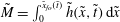 $\tilde{M}=\int _{0}^{\tilde{x}_{fo}(\tilde{t})}\tilde{h}(\tilde{x},\tilde{t})\,\text{d}\tilde{x}$
, which gives
$\tilde{M}=\int _{0}^{\tilde{x}_{fo}(\tilde{t})}\tilde{h}(\tilde{x},\tilde{t})\,\text{d}\tilde{x}$
, which gives
 $$\begin{eqnarray}\tilde{x}_{fo}(\tilde{t})=({\textstyle \frac{5}{3}})^{3/5}\unicode[STIX]{x1D6FC}(\unicode[STIX]{x1D703})^{2/5}\tilde{M}^{3/5}\tilde{t}^{2/5},\end{eqnarray}$$
and a front depth, determined by using (3.4) in (3.3), as
 $$\begin{eqnarray}\tilde{h}_{fo}(\tilde{t})=({\textstyle \frac{5}{3}})^{2/5}\unicode[STIX]{x1D6FC}(\unicode[STIX]{x1D703})^{-2/5}\tilde{M}^{2/5}\tilde{t}^{-2/5}.\end{eqnarray}$$
A bulk flow down an incline at
 $\unicode[STIX]{x1D703}=23^{\circ }$
with
$\unicode[STIX]{x1D703}=23^{\circ }$
with
 $\unicode[STIX]{x1D716}=0.1$
and
$\unicode[STIX]{x1D716}=0.1$
and
 $\tilde{D}=0.01$
,
$\tilde{D}=0.01$
,
 $\tilde{h}_{o}(\tilde{x},\tilde{t})$
at
$\tilde{h}_{o}(\tilde{x},\tilde{t})$
at
 $\tilde{t}=2$
, 4 and 6 is plotted by the dashed line in figure 2. It shows monotonic growth with
$\tilde{t}=2$
, 4 and 6 is plotted by the dashed line in figure 2. It shows monotonic growth with
 $\tilde{x}$
and a shock-like front where
$\tilde{x}$
and a shock-like front where
 $\tilde{h}_{0}$
drops abruptly to zero to generate an unrealistically high slope gradient. A similar height drop at the front has also been reported for more general flow settings in Pudasaini (Reference Pudasaini2011) that later smoothed out by further considering the diffusion term that produced more realistic solutions.
$\tilde{h}_{0}$
drops abruptly to zero to generate an unrealistically high slope gradient. A similar height drop at the front has also been reported for more general flow settings in Pudasaini (Reference Pudasaini2011) that later smoothed out by further considering the diffusion term that produced more realistic solutions.

Figure 2. Scaled surface profile by the outer solution,
 $\tilde{h}$
, the composite solution,
$\tilde{h}$
, the composite solution,
 $\tilde{h}_{c}$
, and the composite coherence length,
$\tilde{h}_{c}$
, and the composite coherence length,
 $\tilde{l}_{c}$
, at
$\tilde{l}_{c}$
, at
 $\tilde{t}=2$
, 4 and 6 (
$\tilde{t}=2$
, 4 and 6 (
 $\unicode[STIX]{x1D703}=23^{\circ }$
,
$\unicode[STIX]{x1D703}=23^{\circ }$
,
 $\unicode[STIX]{x1D703}_{r}=21^{\circ }$
,
$\unicode[STIX]{x1D703}_{r}=21^{\circ }$
,
 $\unicode[STIX]{x1D716}=0.1$
,
$\unicode[STIX]{x1D716}=0.1$
,
 $\tilde{D}=0.01$
).
$\tilde{D}=0.01$
).
3.2 Inner solution and the composite surface profile
According to the matched asymptotic method, the inner solution is sought on a stretched coordinate system moving with
 $\tilde{x}_{fo}(\tilde{t})$
as sketched in figure 3(a). The dimensionless inner variables are denoted by a subscript
$\tilde{x}_{fo}(\tilde{t})$
as sketched in figure 3(a). The dimensionless inner variables are denoted by a subscript
 $i$
as
$i$
as
 $$\begin{eqnarray}\tilde{x}_{i}=\frac{\tilde{x}-\tilde{x}_{fo}(\tilde{t})}{\unicode[STIX]{x1D716}}\quad \text{and}\quad \tilde{h}_{i}=\tilde{h}.\end{eqnarray}$$
The advection–diffusion equation (2.24) in terms of the inner variables becomes
 $$\begin{eqnarray}\unicode[STIX]{x1D716}\frac{\unicode[STIX]{x2202}\tilde{h}_{i}}{\unicode[STIX]{x2202}\tilde{t}}+[\unicode[STIX]{x1D6FC}(\unicode[STIX]{x1D703})\tilde{h}_{i}^{3/2}-\dot{\tilde{x}}_{fo}(\tilde{t})]\frac{\unicode[STIX]{x2202}\tilde{h}_{i}}{\unicode[STIX]{x2202}\tilde{x}_{i}}=\frac{2}{5}\frac{\unicode[STIX]{x2202}}{\unicode[STIX]{x2202}\tilde{x}_{i}}\left(\unicode[STIX]{x1D6FE}(\unicode[STIX]{x1D703})\tilde{h}_{i}^{5/2}\frac{\unicode[STIX]{x2202}\tilde{h}_{i}}{\unicode[STIX]{x2202}\tilde{x}_{i}}\right),\end{eqnarray}$$
which appears quasi-steady on the moving reference frame to the leading order as
 $\unicode[STIX]{x1D716}\rightarrow 0$
. Integration with respect to
$\unicode[STIX]{x1D716}\rightarrow 0$
. Integration with respect to
 $\tilde{x}_{i}$
leads to
$\tilde{x}_{i}$
leads to
 $$\begin{eqnarray}\left\{\frac{2}{5}\left[\unicode[STIX]{x1D6FC}(\unicode[STIX]{x1D703})-\unicode[STIX]{x1D6FE}(\unicode[STIX]{x1D703})\frac{\unicode[STIX]{x2202}\tilde{h}_{i}}{\unicode[STIX]{x2202}\tilde{x}_{i}}\right]\tilde{h}_{i}^{3/2}-\dot{\tilde{x}}_{fo}(\tilde{t})\right\}\tilde{h}_{i}=G(\tilde{t}),\end{eqnarray}$$
for which
 $G(\tilde{t})=0$
is required to ensure a vanished flow height at the front. Excluding the trivial solution of
$G(\tilde{t})=0$
is required to ensure a vanished flow height at the front. Excluding the trivial solution of
 $\tilde{h}_{i}=0$
, we obtain
$\tilde{h}_{i}=0$
, we obtain
 $(2/5)[\unicode[STIX]{x1D6FC}(\unicode[STIX]{x1D703})-\unicode[STIX]{x2202}\tilde{h}_{i}/\unicode[STIX]{x2202}\tilde{x}_{i}]\tilde{h}^{3/2}-\dot{\tilde{x}}_{fo}(\tilde{t})=0$
. If expressing
$(2/5)[\unicode[STIX]{x1D6FC}(\unicode[STIX]{x1D703})-\unicode[STIX]{x2202}\tilde{h}_{i}/\unicode[STIX]{x2202}\tilde{x}_{i}]\tilde{h}^{3/2}-\dot{\tilde{x}}_{fo}(\tilde{t})=0$
. If expressing
 $\dot{\tilde{x}}_{fo}(t)$
in terms of
$\dot{\tilde{x}}_{fo}(t)$
in terms of
 $\tilde{h}_{fo}(\tilde{t})$
by (3.4) and (3.5), we obtain
$\tilde{h}_{fo}(\tilde{t})$
by (3.4) and (3.5), we obtain
 $$\begin{eqnarray}\frac{\unicode[STIX]{x2202}\tilde{h}_{i}}{\unicode[STIX]{x2202}\tilde{x}_{i}}=\frac{\unicode[STIX]{x1D6FC}(\unicode[STIX]{x1D703})}{\unicode[STIX]{x1D6FE}(\unicode[STIX]{x1D703})}\left[1-\left(\frac{\tilde{h}_{fo}(\tilde{t})}{\tilde{h}_{i}}\right)^{3/2}\right].\end{eqnarray}$$
Another integration of (3.9) with respect to the stretched coordinate yields an implicit solution for the inner flow surface profile, with
 $Z=\tilde{h}_{i}/\tilde{h}_{fo}(\tilde{t})$
and
$Z=\tilde{h}_{i}/\tilde{h}_{fo}(\tilde{t})$
and
 $X=\tilde{x}_{i}/\tilde{h}_{fo}(\tilde{t})$
, as
$X=\tilde{x}_{i}/\tilde{h}_{fo}(\tilde{t})$
, as
 $$\begin{eqnarray}Z+\frac{2}{\sqrt{3}}\arctan \left(\frac{1+2\sqrt{Z}}{\sqrt{3}}\right)+\frac{1}{3}\ln \left[\frac{(1-\sqrt{Z})^{2}}{1+\sqrt{Z}+Z}\right]=\frac{\unicode[STIX]{x1D6FC}(\unicode[STIX]{x1D703})}{\unicode[STIX]{x1D6FE}(\unicode[STIX]{x1D703})}X+C_{0}.\end{eqnarray}$$
The integration constant
 $C_{0}$
is determined by the mass redistribution condition with respect to
$C_{0}$
is determined by the mass redistribution condition with respect to
 $\tilde{x}_{i}=0$
(Huang & Garcia Reference Huang and Garcia1998) as
$\tilde{x}_{i}=0$
(Huang & Garcia Reference Huang and Garcia1998) as
 $$\begin{eqnarray}\int _{-\infty }^{0}(\tilde{h}_{fo}-\tilde{h}_{i})\,\text{d}\tilde{x}_{i}=\int _{0}^{\unicode[STIX]{x1D6FF}}\tilde{h}_{i}\,\text{d}\tilde{x}_{i},\end{eqnarray}$$
where
 $\unicode[STIX]{x1D6FF}$
denotes the displaced inner flow front as marked in figure 3(a). By changing the integration variable from
$\unicode[STIX]{x1D6FF}$
denotes the displaced inner flow front as marked in figure 3(a). By changing the integration variable from
 $\tilde{h}_{i}(\tilde{x}_{i},\tilde{t})$
to
$\tilde{h}_{i}(\tilde{x}_{i},\tilde{t})$
to
 $\tilde{x}_{i}(\tilde{h}_{i},\tilde{t})$
, equation (3.11) becomes
$\tilde{x}_{i}(\tilde{h}_{i},\tilde{t})$
, equation (3.11) becomes
 $\int _{0}^{\tilde{h}_{fo}(\tilde{t})}\tilde{x}_{i}\,\text{d}\tilde{h}_{i}=0$
or, equivalently,
$\int _{0}^{\tilde{h}_{fo}(\tilde{t})}\tilde{x}_{i}\,\text{d}\tilde{h}_{i}=0$
or, equivalently,
 $\int _{0}^{1}X(Z)\,\text{d}Z=0$
, which determines
$\int _{0}^{1}X(Z)\,\text{d}Z=0$
, which determines
 $C_{0}=-3/2+\unicode[STIX]{x03C0}/\sqrt{3}$
.
$C_{0}=-3/2+\unicode[STIX]{x03C0}/\sqrt{3}$
.

Figure 3. (a) Schematic diagram of the inner coordinate system and the inner free-surface profile. (b) The illustration of the outer, inner and composite free-surface profiles (
 $\unicode[STIX]{x1D703}=25^{\circ }$
,
$\unicode[STIX]{x1D703}=25^{\circ }$
,
 $\tilde{t}=2$
,
$\tilde{t}=2$
,
 $\unicode[STIX]{x1D703}_{r}=21^{\circ }$
,
$\unicode[STIX]{x1D703}_{r}=21^{\circ }$
,
 $\unicode[STIX]{x1D716}=0.1$
,
$\unicode[STIX]{x1D716}=0.1$
,
 $\tilde{D}=0.01$
).
$\tilde{D}=0.01$
).
Next, a composite solution is constructed by patching the outer and the inner solutions and then removing their overlap. From (3.11), it is straightforward to show that the inner solution asymptotes to
 $\tilde{h}_{fo}(\tilde{t})$
, so that it automatically matches the outer solution,
$\tilde{h}_{fo}(\tilde{t})$
, so that it automatically matches the outer solution,
 $$\begin{eqnarray}\lim _{\tilde{x}_{i}\rightarrow -\infty }\tilde{h}_{i}=\lim _{\tilde{x}\rightarrow \tilde{x}_{fo}(\tilde{t})}\tilde{h}=\tilde{h}_{fo}(\tilde{t}).\end{eqnarray}$$
Hence, their overlap is simply
 $\tilde{h}_{fo}(\tilde{t})$
and the final composite solution, denoted by a subscript ‘
$\tilde{h}_{fo}(\tilde{t})$
and the final composite solution, denoted by a subscript ‘
 $c$
’, is found as
$c$
’, is found as
 $$\begin{eqnarray}\tilde{h}_{c}(\tilde{x},\tilde{t})=\tilde{h}_{o}(\tilde{x},\tilde{t})+\tilde{h}_{i}(\tilde{x},\tilde{t})-\tilde{h}_{fo}(\tilde{t}),\end{eqnarray}$$
as illustrated for a typical flow case in figure 3(b). The composite surface profile exhibits smoother variation across the spreading length than the outer solution.
The modified flow-front composite trajectory is determined by adding the shifted inner flow front to the outer solution as
 $\tilde{x}_{fc}(\tilde{t})=\tilde{x}_{fo}(\tilde{t})+\unicode[STIX]{x1D716}\unicode[STIX]{x1D6FF}$
, with
$\tilde{x}_{fc}(\tilde{t})=\tilde{x}_{fo}(\tilde{t})+\unicode[STIX]{x1D716}\unicode[STIX]{x1D6FF}$
, with
 $\unicode[STIX]{x1D6FF}$
being determined specifically by where the inner flow surface diminishes smoothly to zero,
$\unicode[STIX]{x1D6FF}$
being determined specifically by where the inner flow surface diminishes smoothly to zero,
 $\unicode[STIX]{x1D6FF}=\tilde{x}_{i}(\tilde{h}_{i}=0)$
, to obtain
$\unicode[STIX]{x1D6FF}=\tilde{x}_{i}(\tilde{h}_{i}=0)$
, to obtain
 $$\begin{eqnarray}\tilde{x}_{fc}(\tilde{t})=\left(\frac{5}{3}\right)^{3/5}\unicode[STIX]{x1D6FC}(\unicode[STIX]{x1D703})^{2/5}\tilde{t}^{2/5}+\unicode[STIX]{x1D716}\left(\frac{3}{2}+\frac{2\unicode[STIX]{x03C0}}{3\sqrt{3}}\right)\left(\frac{5}{3}\right)^{2/5}\unicode[STIX]{x1D6FC}(\unicode[STIX]{x1D703})^{-7/5}\unicode[STIX]{x1D6FE}(\unicode[STIX]{x1D703})\tilde{t}^{-2/5}.\end{eqnarray}$$
The composite solution for the front trajectory is compared to the outer solution in figure 4 for the motion studied in figure 2. The composite front
 $\tilde{x}_{fc}(\tilde{t})$
is found to advance
$\tilde{x}_{fc}(\tilde{t})$
is found to advance
 $\tilde{x}_{fo}(\tilde{t})$
at a seemingly too drastic manner at small times due to the diverging nature of
$\tilde{x}_{fo}(\tilde{t})$
at a seemingly too drastic manner at small times due to the diverging nature of
 $\unicode[STIX]{x1D6FF}\sim \tilde{t}^{-2/5}$
when
$\unicode[STIX]{x1D6FF}\sim \tilde{t}^{-2/5}$
when
 $\tilde{t}\rightarrow 0$
. Such a singularity is inevitable since the assumption of
$\tilde{t}\rightarrow 0$
. Such a singularity is inevitable since the assumption of
 $\unicode[STIX]{x1D716}\ll 1$
is seldom met shortly after the onset of motion and is degraded when the mass propagates into a shallow configuration at later times.
$\unicode[STIX]{x1D716}\ll 1$
is seldom met shortly after the onset of motion and is degraded when the mass propagates into a shallow configuration at later times.

Figure 4. Comparison of the scaled flow-front trajectory by the outer, composite and modified solutions as
 $\tilde{x}_{f}$
,
$\tilde{x}_{f}$
,
 $\tilde{x}_{fc}$
and
$\tilde{x}_{fc}$
and
 $\tilde{x}_{fm}$
, respectively. The deposit-front trajectory,
$\tilde{x}_{fm}$
, respectively. The deposit-front trajectory,
 $\tilde{x}_{d}$
, is also shown with the run-out,
$\tilde{x}_{d}$
, is also shown with the run-out,
 $\tilde{L}_{d}$
, and the arrest time,
$\tilde{L}_{d}$
, and the arrest time,
 $\tilde{T}_{d}$
, marked (
$\tilde{T}_{d}$
, marked (
 $\unicode[STIX]{x1D703}=23^{\circ }$
,
$\unicode[STIX]{x1D703}=23^{\circ }$
,
 $\unicode[STIX]{x1D703}_{r}=21^{\circ }$
,
$\unicode[STIX]{x1D703}_{r}=21^{\circ }$
,
 $\unicode[STIX]{x1D716}=0.1$
,
$\unicode[STIX]{x1D716}=0.1$
,
 $\tilde{D}=0.01$
).
$\tilde{D}=0.01$
).
3.3 Local coherence length and flow regimes
The composite flow solution is now employed to investigate how the coherence length,
 $l$
, develops with the flow. In the limit of
$l$
, develops with the flow. In the limit of
 $\unicode[STIX]{x1D716}\rightarrow 0$
, equations (2.19) and (2.21) give
$\unicode[STIX]{x1D716}\rightarrow 0$
, equations (2.19) and (2.21) give
 $$\begin{eqnarray}\tilde{l}_{o}=\frac{\sin \unicode[STIX]{x1D703}_{r}\,\hat{b}\tilde{D}}{\sin \unicode[STIX]{x1D703}-\sin \unicode[STIX]{x1D703}_{r}},\end{eqnarray}$$
which is the outer solution of the coherence length valid for
 $\tilde{x}\ll \tilde{x}_{f}(\tilde{t})$
. When
$\tilde{x}\ll \tilde{x}_{f}(\tilde{t})$
. When
 $\tilde{x}\sim \tilde{x}_{f}(\tilde{t})$
, equation (2.19) gives
$\tilde{x}\sim \tilde{x}_{f}(\tilde{t})$
, equation (2.19) gives
 $\tilde{l}_{i}=\sin \unicode[STIX]{x1D703}_{r}\,\hat{b}\tilde{D}(\sin \unicode[STIX]{x1D703}-\cos \unicode[STIX]{x1D703}\,\unicode[STIX]{x2202}\tilde{h}_{i}/\unicode[STIX]{x2202}\tilde{x}_{i}-\sin \unicode[STIX]{x1D703}_{r})^{-1}$
in the inner coordinate system and the local
$\tilde{l}_{i}=\sin \unicode[STIX]{x1D703}_{r}\,\hat{b}\tilde{D}(\sin \unicode[STIX]{x1D703}-\cos \unicode[STIX]{x1D703}\,\unicode[STIX]{x2202}\tilde{h}_{i}/\unicode[STIX]{x2202}\tilde{x}_{i}-\sin \unicode[STIX]{x1D703}_{r})^{-1}$
in the inner coordinate system and the local
 $\unicode[STIX]{x2202}\tilde{h}_{i}/\unicode[STIX]{x2202}\tilde{x}_{i}$
can be replaced by (3.9) to give
$\unicode[STIX]{x2202}\tilde{h}_{i}/\unicode[STIX]{x2202}\tilde{x}_{i}$
can be replaced by (3.9) to give
 $$\begin{eqnarray}\tilde{l}_{i}=\frac{\sqrt{\sin \unicode[STIX]{x1D703}_{r}}}{\unicode[STIX]{x1D6FC}(\unicode[STIX]{x1D703})}\left(\frac{\tilde{h}_{i}}{\tilde{h}_{fo}}\right)^{3/2}.\end{eqnarray}$$
It is straightforward to show that the inner coherence length asymptotes to the outer solution,
 $\lim _{\tilde{x}_{i}\rightarrow -\infty }\tilde{l}_{i}=\tilde{l}_{o}$
, so that the overlap solution is, again, the outer solution and the composite solution can be found readily as
$\lim _{\tilde{x}_{i}\rightarrow -\infty }\tilde{l}_{i}=\tilde{l}_{o}$
, so that the overlap solution is, again, the outer solution and the composite solution can be found readily as
 $\tilde{l}_{c}=\tilde{l}_{o}+\tilde{l}_{i}-\tilde{l}_{o}=\tilde{l}_{i}$
. By expressing (3.16) in terms of
$\tilde{l}_{c}=\tilde{l}_{o}+\tilde{l}_{i}-\tilde{l}_{o}=\tilde{l}_{i}$
. By expressing (3.16) in terms of
 $\tilde{l}_{o}$
, we obtain
$\tilde{l}_{o}$
, we obtain
 $$\begin{eqnarray}\tilde{l}_{c}=Z^{3/2}\tilde{l}_{o},\end{eqnarray}$$
clearly showing that the profile of
 $\tilde{l}_{c}$
is governed by the implicit solution of
$\tilde{l}_{c}$
is governed by the implicit solution of
 $Z=\tilde{h}_{i}/\tilde{h}_{fo}$
from (3.10) near the front but asymptotes to constant
$Z=\tilde{h}_{i}/\tilde{h}_{fo}$
from (3.10) near the front but asymptotes to constant
 $\tilde{l}_{o}$
when
$\tilde{l}_{o}$
when
 $\tilde{x}\ll \tilde{x}_{f}(\tilde{t})$
. When the instantaneous coherence length profile for the flow cases examined in figure 2 are shown by the solid grey lines on the same plot,
$\tilde{x}\ll \tilde{x}_{f}(\tilde{t})$
. When the instantaneous coherence length profile for the flow cases examined in figure 2 are shown by the solid grey lines on the same plot,
 $\tilde{l}_{c}(\tilde{x},\tilde{t})$
is found to increase monotonically from zero at the flow front onto a plateau of
$\tilde{l}_{c}(\tilde{x},\tilde{t})$
is found to increase monotonically from zero at the flow front onto a plateau of
 $\tilde{l}_{o}$
in the rear.
$\tilde{l}_{o}$
in the rear.
The relative magnitude of
 $\tilde{l}_{c}(\tilde{x},\tilde{t})$
and
$\tilde{l}_{c}(\tilde{x},\tilde{t})$
and
 $\tilde{h}_{c}(\tilde{x},\tilde{t})$
can be utilized to categorize bulk motion into different regimes as follows. When
$\tilde{h}_{c}(\tilde{x},\tilde{t})$
can be utilized to categorize bulk motion into different regimes as follows. When
 $\tilde{h}_{c}\gg \tilde{l}_{c}$
in the front, the majority of the material is in the flowing state and the diminished
$\tilde{h}_{c}\gg \tilde{l}_{c}$
in the front, the majority of the material is in the flowing state and the diminished
 $\tilde{l}_{c}$
at the front signals free and agitated grain motions therein, which agrees qualitatively with the experimental observations at a surging front (Pouliquen & Forterre Reference Pouliquen and Forterre2002; Kokelaar et al.
Reference Kokelaar, Graham, Gray and Vallance2014). When
$\tilde{l}_{c}$
at the front signals free and agitated grain motions therein, which agrees qualitatively with the experimental observations at a surging front (Pouliquen & Forterre Reference Pouliquen and Forterre2002; Kokelaar et al.
Reference Kokelaar, Graham, Gray and Vallance2014). When
 $\tilde{l}_{c}$
grows comparable to
$\tilde{l}_{c}$
grows comparable to
 $\tilde{h}_{c}$
in the rear, effective spatial correlation across the layer develops to transmit the bulk-arresting decelerating impulse due to basal friction, so that the deposit develops from the base as shown by Pudasaini (Reference Pudasaini2011). Such a fluid-to-solid transition first takes place in the rear where
$\tilde{h}_{c}$
in the rear, effective spatial correlation across the layer develops to transmit the bulk-arresting decelerating impulse due to basal friction, so that the deposit develops from the base as shown by Pudasaini (Reference Pudasaini2011). Such a fluid-to-solid transition first takes place in the rear where
 $\tilde{h}_{c}(\tilde{t})\sim \tilde{l}_{c}$
and propagates towards the front as
$\tilde{h}_{c}(\tilde{t})\sim \tilde{l}_{c}$
and propagates towards the front as
 $\tilde{h}_{c}$
diminishes when the mass evolves downstream (see figure 1). Such a deposition wave phenomenon has been observed in experiments (Borzsonyi et al.
Reference Borzsonyi, Halsey and Ecke2008; Edwards & Gray Reference Edwards and Gray2014).
$\tilde{h}_{c}$
diminishes when the mass evolves downstream (see figure 1). Such a deposition wave phenomenon has been observed in experiments (Borzsonyi et al.
Reference Borzsonyi, Halsey and Ecke2008; Edwards & Gray Reference Edwards and Gray2014).
4 Propagation of the deposit front and the arrested state
4.1 Leading-order solutions
As stated in § 3, the current model assumes that a static deposit develops from the base when
 $\tilde{l}$
becomes comparable to
$\tilde{l}$
becomes comparable to
 $\tilde{h}$
at
$\tilde{h}$
at
 $\tilde{x}_{d}$
. Hence, the flow solutions remain unaffected for
$\tilde{x}_{d}$
. Hence, the flow solutions remain unaffected for
 $\tilde{x}>\tilde{x}_{d}$
and the local flow height as well as the propagation speed of the deposition front at
$\tilde{x}>\tilde{x}_{d}$
and the local flow height as well as the propagation speed of the deposition front at
 $\tilde{x}_{d}$
can be described by (2.26) as
$\tilde{x}_{d}$
can be described by (2.26) as
 $$\begin{eqnarray}\displaystyle & \displaystyle \frac{\text{d}\tilde{h}_{d}}{\text{d}\tilde{t}}=\unicode[STIX]{x1D716}\left.\frac{\unicode[STIX]{x2202}}{\unicode[STIX]{x2202}\tilde{x}}\left[\frac{2}{5}\unicode[STIX]{x1D6FE}(\unicode[STIX]{x1D703})\tilde{h}^{5/2}\frac{\unicode[STIX]{x2202}\tilde{h}}{\unicode[STIX]{x2202}\tilde{x}}\right]\right|_{\tilde{x}=\tilde{x}_{d}(\tilde{t})}, & \displaystyle\end{eqnarray}$$
 $$\begin{eqnarray}\displaystyle & \displaystyle \dot{\tilde{x}}_{d}(\tilde{t})=\unicode[STIX]{x1D6FC}(\unicode[STIX]{x1D703})\tilde{h}_{d}^{3/2}(\tilde{t}), & \displaystyle\end{eqnarray}$$
assuming that
 $\tilde{x}_{d}$
is known a priori. Hence, we follow Ertas & Halsey (Reference Ertas and Halsey2002) to determine an instantaneous
$\tilde{x}_{d}$
is known a priori. Hence, we follow Ertas & Halsey (Reference Ertas and Halsey2002) to determine an instantaneous
 $\tilde{x}_{d}(\tilde{t})$
by
$\tilde{x}_{d}(\tilde{t})$
by
 $$\begin{eqnarray}\tilde{h}_{d}(\tilde{t})={\hat{c}}\tilde{l}(\tilde{x}_{d}(\tilde{t}),\tilde{t}).\end{eqnarray}$$
Here, the coefficient constant
 ${\hat{c}}$
is set to the value in the dimensional relation
${\hat{c}}$
is set to the value in the dimensional relation
 $h_{stop}(\unicode[STIX]{x1D703})={\hat{c}}l(\unicode[STIX]{x1D703})$
used by Ertas & Halsey (Reference Ertas and Halsey2002) to specify the relationship between the coherence length in a uniform surface flow and the thickness threshold
$h_{stop}(\unicode[STIX]{x1D703})={\hat{c}}l(\unicode[STIX]{x1D703})$
used by Ertas & Halsey (Reference Ertas and Halsey2002) to specify the relationship between the coherence length in a uniform surface flow and the thickness threshold
 $h_{stop}$
. This is because the two relations in uniform steady and non-uniform unsteady flows are conceptually equivalent and only differ in how the flow-to-no-flow transition develops with the flow. For steady flows of uniform thickness, the transition takes place immediately across the layer and the flow stops en masse. When the bulk surface is non-uniform and changes with time, a static layer can develop gradually from the bed to the free surface although in a manner yet unresolved from the current model. That is why the solid–fluid interface is sketched schematically by both a concave and another convex dashed line in figure 1 to show its undetermined nature. Nonetheless, a leading-order estimation of the total mass run-out and arrest time can still be attempted using the assumed unaffected flow solutions above the just-formed deposit at
$h_{stop}$
. This is because the two relations in uniform steady and non-uniform unsteady flows are conceptually equivalent and only differ in how the flow-to-no-flow transition develops with the flow. For steady flows of uniform thickness, the transition takes place immediately across the layer and the flow stops en masse. When the bulk surface is non-uniform and changes with time, a static layer can develop gradually from the bed to the free surface although in a manner yet unresolved from the current model. That is why the solid–fluid interface is sketched schematically by both a concave and another convex dashed line in figure 1 to show its undetermined nature. Nonetheless, a leading-order estimation of the total mass run-out and arrest time can still be attempted using the assumed unaffected flow solutions above the just-formed deposit at
 $\tilde{x}=\tilde{x}_{d}$
as follows.
$\tilde{x}=\tilde{x}_{d}$
as follows.
Firstly, an arrest time,
 $\tilde{T}_{d}$
, for the total mass to halt can be estimated by requiring total mass conservation,
$\tilde{T}_{d}$
, for the total mass to halt can be estimated by requiring total mass conservation,
 $$\begin{eqnarray}\tilde{M}=\int _{0}^{\tilde{T}_{d}}\dot{\tilde{x}}_{d}(\tilde{t})\tilde{h}_{d}(\tilde{t})\,\text{d}\tilde{t},\end{eqnarray}$$
where
 $\dot{\tilde{x}}_{d}(\tilde{t})\tilde{h}_{d}(\tilde{t})$
is the mass flux across a normal plane at
$\dot{\tilde{x}}_{d}(\tilde{t})\tilde{h}_{d}(\tilde{t})$
is the mass flux across a normal plane at
 $\tilde{x}_{d}(\tilde{t})$
. We now seek the leading-order solution of the above deposit-front model. In the limit of
$\tilde{x}_{d}(\tilde{t})$
. We now seek the leading-order solution of the above deposit-front model. In the limit of
 $\unicode[STIX]{x1D716}\rightarrow 0$
, equation (4.1) gives
$\unicode[STIX]{x1D716}\rightarrow 0$
, equation (4.1) gives
 $$\begin{eqnarray}\frac{\text{d}\tilde{h}_{d}}{\text{d}\tilde{t}}=0,\end{eqnarray}$$
and hence a time-invariant constant may be estimated to the leading order using the outer constant solution in (3.15) as
 $$\begin{eqnarray}\tilde{h}_{d}={\hat{c}}\tilde{l}_{o}.\end{eqnarray}$$
This in turn gives a constant speed for the deposition front by (4.2). Hence, the integrand in (4.4) is independent of
 $\tilde{t}$
, to the leading order, so that it is straightforward to obtain
$\tilde{t}$
, to the leading order, so that it is straightforward to obtain
 $$\begin{eqnarray}\tilde{T}_{d}=\tilde{M}\hat{b}^{-3/2}{\hat{c}}^{-3/2}\tilde{D}^{-3/2}\sqrt{\sin \unicode[STIX]{x1D703}_{r}}\,(\sin \unicode[STIX]{x1D703}-\sin \unicode[STIX]{x1D703}_{r})^{3/2}.\end{eqnarray}$$
With
 $\dot{\tilde{x}}_{d}$
and
$\dot{\tilde{x}}_{d}$
and
 $\tilde{T}_{d}$
, a leading-order estimation of the total run-out distance can be found readily as
$\tilde{T}_{d}$
, a leading-order estimation of the total run-out distance can be found readily as
 $$\begin{eqnarray}\tilde{L}_{d}=\int _{0}^{\tilde{T}_{d}}\dot{\tilde{x}}_{d}(\tilde{t})\,\text{d}\tilde{t}=\tilde{M}\hat{b}^{-1}\tilde{D}^{-1}(\sin \unicode[STIX]{x1D703}-\sin \unicode[STIX]{x1D703}_{r}).\end{eqnarray}$$
4.2 Modified flow-front solution
It is apparent that the finite
 $\tilde{L}_{d}$
given by (4.8) is inconsistent with the front trajectory profiles found in the outer and the composite solution in (3.4) and (3.14) that give an unstoppable solution and hence an infinite run-out as also found in Pudasaini (Reference Pudasaini2011). The discrepancy is attributed to the assumptions that the solid deposit does not affect the flow solutions. The current stress model may underestimate flow resistance since internal friction at the fluid-to-solid interface is not considered and neither is the possible momentum loss during the deposition process. To construct a more realistic front trajectory profile within the current framework, we try to adapt the asymptotic solution to meet the requirement that the flow front arrests as soon as it travels over
$\tilde{L}_{d}$
given by (4.8) is inconsistent with the front trajectory profiles found in the outer and the composite solution in (3.4) and (3.14) that give an unstoppable solution and hence an infinite run-out as also found in Pudasaini (Reference Pudasaini2011). The discrepancy is attributed to the assumptions that the solid deposit does not affect the flow solutions. The current stress model may underestimate flow resistance since internal friction at the fluid-to-solid interface is not considered and neither is the possible momentum loss during the deposition process. To construct a more realistic front trajectory profile within the current framework, we try to adapt the asymptotic solution to meet the requirement that the flow front arrests as soon as it travels over
 $\tilde{L}_{d}$
at
$\tilde{L}_{d}$
at
 $\tilde{t}=\tilde{T}_{d}$
. For simplicity, such a modification is proposed for the outer solution (3.4) by imposing an ad hoc prefactor to generate the modified front trajectory as
$\tilde{t}=\tilde{T}_{d}$
. For simplicity, such a modification is proposed for the outer solution (3.4) by imposing an ad hoc prefactor to generate the modified front trajectory as
 $$\begin{eqnarray}\tilde{x}_{fm}(\tilde{t})=\left[1-\hat{f}\left(\frac{\tilde{t}}{\tilde{T}_{d}}\right)^{{\hat{g}}}\right]\tilde{x}_{fo}(\tilde{t}),\end{eqnarray}$$
with two unknown constants
 $\hat{f}$
and
$\hat{f}$
and
 ${\hat{g}}$
. By requiring
${\hat{g}}$
. By requiring
 $\tilde{x}_{fm}(\tilde{T}_{d})=\tilde{L}_{d}$
and
$\tilde{x}_{fm}(\tilde{T}_{d})=\tilde{L}_{d}$
and
 $\dot{\tilde{x}}_{fm}(\tilde{T}_{d})=0$
,
$\dot{\tilde{x}}_{fm}(\tilde{T}_{d})=0$
,
 $\hat{f}=1-(3/5)^{3/5}$
and
$\hat{f}=1-(3/5)^{3/5}$
and
 ${\hat{g}}=(2/5)(1-\hat{f})/\hat{f}$
. A similar solution may be constructed using the composite front trajectory (3.14), which leads to more complex results. When the modified front trajectory is presented on figure 4,
${\hat{g}}=(2/5)(1-\hat{f})/\hat{f}$
. A similar solution may be constructed using the composite front trajectory (3.14), which leads to more complex results. When the modified front trajectory is presented on figure 4,
 $\tilde{x}_{fm}(\tilde{t})$
is observed to asymptote to
$\tilde{x}_{fm}(\tilde{t})$
is observed to asymptote to
 $\tilde{x}_{fo}(\tilde{t})$
at early times but decelerate smoothly to the run-out
$\tilde{x}_{fo}(\tilde{t})$
at early times but decelerate smoothly to the run-out
 $\tilde{L}_{d}$
at the intersection of
$\tilde{L}_{d}$
at the intersection of
 $\tilde{x}_{fm}(\tilde{t})$
and
$\tilde{x}_{fm}(\tilde{t})$
and
 $\tilde{x}_{d}(\tilde{t})$
at
$\tilde{x}_{d}(\tilde{t})$
at
 $\tilde{t}=\tilde{T}_{d}$
. The trajectories of
$\tilde{t}=\tilde{T}_{d}$
. The trajectories of
 $\tilde{x}_{fm}(\tilde{t})$
and
$\tilde{x}_{fm}(\tilde{t})$
and
 $\tilde{x}_{d}(\tilde{t})$
for flows under different
$\tilde{x}_{d}(\tilde{t})$
for flows under different
 $\unicode[STIX]{x1D703}$
are plotted in figure 5, showing longer deposits and arrest time on steeper inclines.
$\unicode[STIX]{x1D703}$
are plotted in figure 5, showing longer deposits and arrest time on steeper inclines.

Figure 5. Comparison of the modified front trajectory
 $\tilde{x}_{fm}$
(thick solid line) with
$\tilde{x}_{fm}$
(thick solid line) with
 $\tilde{x}_{d}$
(thin solid line) for
$\tilde{x}_{d}$
(thin solid line) for
 $\unicode[STIX]{x1D703}=23^{\circ },24^{\circ },25^{\circ }$
, where
$\unicode[STIX]{x1D703}=23^{\circ },24^{\circ },25^{\circ }$
, where
 $\unicode[STIX]{x1D703}_{r}=21^{\circ }$
,
$\unicode[STIX]{x1D703}_{r}=21^{\circ }$
,
 $\unicode[STIX]{x1D716}=0.1$
,
$\unicode[STIX]{x1D716}=0.1$
,
 $\tilde{D}=0.01$
.
$\tilde{D}=0.01$
.
4.3 Comparison with experimental data
The current results of the modified flow front in (4.9) and the leading-order arrest time and run-out in (4.7) and (4.8) are evaluated by comparison with the experimental data reported in Pouliquen & Forterre (Reference Pouliquen and Forterre2002). Those authors studied the spreading of finite glass beads (
 $D=0.5~\text{mm}$
) from spherical caps of different sizes down a rough incline at different inclination angles, and the results for the medium cap are considered here. Since the current analysis is two-dimensional, justification and explanations are given below for how we interpreted the three-dimensional experimental data in the reference.
$D=0.5~\text{mm}$
) from spherical caps of different sizes down a rough incline at different inclination angles, and the results for the medium cap are considered here. Since the current analysis is two-dimensional, justification and explanations are given below for how we interpreted the three-dimensional experimental data in the reference.
Judging from figures 5(a), 6 and 7(a) in Pouliquen & Forterre (Reference Pouliquen and Forterre2002) for the top view of a granular mass down an incline at
 $\unicode[STIX]{x1D703}=23^{\circ }$
, the instantaneous flow width in the consecutive snapshots shortly after the release remains nearly constant. The final deposit widths for releases on different slopes are also close to each other. Both observations suggest that the lateral spreading mechanism is rather insensitive to changes in the examined flow conditions and hence is assumed here to be much weaker than streamwise propagation. As a result, the flow can be fairly regarded as quasi-two-dimensional with a total volume per unit width of
$\unicode[STIX]{x1D703}=23^{\circ }$
, the instantaneous flow width in the consecutive snapshots shortly after the release remains nearly constant. The final deposit widths for releases on different slopes are also close to each other. Both observations suggest that the lateral spreading mechanism is rather insensitive to changes in the examined flow conditions and hence is assumed here to be much weaker than streamwise propagation. As a result, the flow can be fairly regarded as quasi-two-dimensional with a total volume per unit width of
 $M/\unicode[STIX]{x1D70C}\simeq 13~\text{cm}^{2}$
. This value is estimated here by the projection area of the deposit at
$M/\unicode[STIX]{x1D70C}\simeq 13~\text{cm}^{2}$
. This value is estimated here by the projection area of the deposit at
 $\unicode[STIX]{x1D703}=23^{\circ }$
shown in their figure 6(c), which may be overestimated since the transverse surface curvature is neglected. A closer look at the surface contour lines provided therein reveals that such approximation of a quasi-two-dimensional block mass is more feasible at later times. However, the effect of the varying degree of an overestimated mass falls beyond the scope of this work and is not further addressed.
$\unicode[STIX]{x1D703}=23^{\circ }$
shown in their figure 6(c), which may be overestimated since the transverse surface curvature is neglected. A closer look at the surface contour lines provided therein reveals that such approximation of a quasi-two-dimensional block mass is more feasible at later times. However, the effect of the varying degree of an overestimated mass falls beyond the scope of this work and is not further addressed.

Figure 6. Comparison of the current prediction with the experimental data reported in Pouliquen & Forterre (Reference Pouliquen and Forterre2002): (a) front trajectory at
 $\unicode[STIX]{x1D703}=23^{\circ }$
with
$\unicode[STIX]{x1D703}=23^{\circ }$
with
 $x_{f}=25$
, 30, 35, 40 and 45 cm extracted here for
$x_{f}=25$
, 30, 35, 40 and 45 cm extracted here for
 $t=0.24$
, 0.48, 0.96, 2.4 and 6 s. (b) Run-out distance under different inclination angles, where
$t=0.24$
, 0.48, 0.96, 2.4 and 6 s. (b) Run-out distance under different inclination angles, where
 $\unicode[STIX]{x1D703}_{r}=21^{\circ }$
is taken to be
$\unicode[STIX]{x1D703}_{r}=21^{\circ }$
is taken to be
 $\unicode[STIX]{x1D703}_{1}$
in Pouliquen & Forterre (Reference Pouliquen and Forterre2002).
$\unicode[STIX]{x1D703}_{1}$
in Pouliquen & Forterre (Reference Pouliquen and Forterre2002).
As suggested by Ertas & Halsey (Reference Ertas and Halsey2002), bulk material constants are evaluated by comparing the model prediction for uniform flows with Pouliquen’s flow rule and
 $h_{stop}$
in the limit of
$h_{stop}$
in the limit of
 $\unicode[STIX]{x1D703}\rightarrow \unicode[STIX]{x1D703}_{r}$
to yield
$\unicode[STIX]{x1D703}\rightarrow \unicode[STIX]{x1D703}_{r}$
to yield
 $$\begin{eqnarray}\unicode[STIX]{x1D703}_{r}=\unicode[STIX]{x1D703}_{1},\quad \hat{b}=\frac{2\mathscr{L}(\tan \unicode[STIX]{x1D703}_{2}-\tan \unicode[STIX]{x1D703}_{1})\cos \unicode[STIX]{x1D703}_{1}}{5\unicode[STIX]{x1D6FD}\sqrt{\sin \unicode[STIX]{x1D703}_{1}}\,D},\quad {\hat{c}}=\frac{5\unicode[STIX]{x1D6FD}}{2\sqrt{\sin \unicode[STIX]{x1D703}_{1}}},\end{eqnarray}$$
where
 $\unicode[STIX]{x1D6FD}=0.136$
,
$\unicode[STIX]{x1D6FD}=0.136$
,
 $\unicode[STIX]{x1D703}_{1}=21^{\circ }$
,
$\unicode[STIX]{x1D703}_{1}=21^{\circ }$
,
 $\unicode[STIX]{x1D703}_{2}=30.7^{\circ }$
,
$\unicode[STIX]{x1D703}_{2}=30.7^{\circ }$
,
 $\mathscr{L}=0.65~\text{mm}$
and
$\mathscr{L}=0.65~\text{mm}$
and
 $D=0.5~\text{mm}$
. Equations (4.9), (4.7) and (4.8) are expressed in dimensional forms as
$D=0.5~\text{mm}$
. Equations (4.9), (4.7) and (4.8) are expressed in dimensional forms as
 $$\begin{eqnarray}x_{fm}(t)=\left(\frac{5}{3}\right)^{3/5}\left(\frac{M}{\unicode[STIX]{x1D70C}}\right)^{3/5}\left(\sqrt{\frac{g}{\sin \unicode[STIX]{x1D703}_{r}}}\frac{\sin \unicode[STIX]{x1D703}-\sin \unicode[STIX]{x1D703}_{r}}{\hat{b}D}\right)^{2/5}\left[1-\hat{f}\left(\frac{t}{T_{d}}\right)^{{\hat{g}}}\right]t^{2/5},\end{eqnarray}$$
with
 $$\begin{eqnarray}T_{d}(\unicode[STIX]{x1D703})=\left(\frac{M}{\unicode[STIX]{x1D70C}}\right)\sqrt{\frac{\sin \unicode[STIX]{x1D703}_{r}}{\hat{b}^{3}{\hat{c}}^{3}D^{3}g}}(\sin \unicode[STIX]{x1D703}-\sin \unicode[STIX]{x1D703}_{r})^{3/2}\end{eqnarray}$$
and
 $$\begin{eqnarray}L_{d}(\unicode[STIX]{x1D703})=\left(\frac{M}{\unicode[STIX]{x1D70C}}\right)\hat{b}^{-1}D^{-1}(\sin \unicode[STIX]{x1D703}-\sin \unicode[STIX]{x1D703}_{r}).\end{eqnarray}$$
Focusing on the flow-front dynamics at
 $\unicode[STIX]{x1D703}=23^{\circ }$
(in the valid range
$\unicode[STIX]{x1D703}=23^{\circ }$
(in the valid range
 $\unicode[STIX]{x1D703}_{r}<\unicode[STIX]{x1D703}<\unicode[STIX]{x1D703}_{2}$
for the current model), the successive front locations are extracted from figure 5(c) in Ertas & Halsey (Reference Ertas and Halsey2002) and compared to the prediction by (4.11a
) in figure 6(a). Qualitative agreement on the nonlinear front trajectory is observed and the predicted arrest time,
$\unicode[STIX]{x1D703}_{r}<\unicode[STIX]{x1D703}<\unicode[STIX]{x1D703}_{2}$
for the current model), the successive front locations are extracted from figure 5(c) in Ertas & Halsey (Reference Ertas and Halsey2002) and compared to the prediction by (4.11a
) in figure 6(a). Qualitative agreement on the nonlinear front trajectory is observed and the predicted arrest time,
 $T_{d}=6.27$
s, is within a 4.5
$T_{d}=6.27$
s, is within a 4.5
 $\%$
overestimation from the measured 6 s. A shorter
$\%$
overestimation from the measured 6 s. A shorter
 $L_{d}$
is therefore predicted throughout the process, which may further result from the following reasons. First, the ad hoc modification is constructed on the outer solution for order consistency and hence does not incorporate the inner flow-front advancement by
$L_{d}$
is therefore predicted throughout the process, which may further result from the following reasons. First, the ad hoc modification is constructed on the outer solution for order consistency and hence does not incorporate the inner flow-front advancement by
 $\unicode[STIX]{x1D6FF}$
in (3.14). Further, the current flow solution neglects the influence of the initial boundary condition on the characteristic line in the derivation of
$\unicode[STIX]{x1D6FF}$
in (3.14). Further, the current flow solution neglects the influence of the initial boundary condition on the characteristic line in the derivation of
 $\tilde{h}_{o}$
in (3.3). Inclusion of
$\tilde{h}_{o}$
in (3.3). Inclusion of
 $\tilde{x}_{0}$
therein should give a greater
$\tilde{x}_{0}$
therein should give a greater
 $\tilde{x}_{fo}(\tilde{t})$
and hence
$\tilde{x}_{fo}(\tilde{t})$
and hence
 $L_{d}$
to reflect the influence of initial packing shape, especially on the slower motion near
$L_{d}$
to reflect the influence of initial packing shape, especially on the slower motion near
 $\unicode[STIX]{x1D703}_{r}$
with shorter run-outs. Finally, the run-outs on different slopes reported in figure 7(b) of Ertas & Halsey (Reference Ertas and Halsey2002) and from the current predictions are also compared in figure 6(b), showing satisfactory agreement when
$\unicode[STIX]{x1D703}_{r}$
with shorter run-outs. Finally, the run-outs on different slopes reported in figure 7(b) of Ertas & Halsey (Reference Ertas and Halsey2002) and from the current predictions are also compared in figure 6(b), showing satisfactory agreement when
 $\unicode[STIX]{x1D703}>23^{\circ }$
. The growing degree of underestimation when
$\unicode[STIX]{x1D703}>23^{\circ }$
. The growing degree of underestimation when
 $\unicode[STIX]{x1D703}\rightarrow \unicode[STIX]{x1D703}_{r}$
clearly illustrates the limitation of the current shear stress model in (1.2) and is further discussed in § 5.
$\unicode[STIX]{x1D703}\rightarrow \unicode[STIX]{x1D703}_{r}$
clearly illustrates the limitation of the current shear stress model in (1.2) and is further discussed in § 5.
5 Summary and discussion
The coherence length model of shear stress and the arresting mechanism proposed by Ertas & Halsey (Reference Ertas and Halsey2002) for steady uniform granular flows down a rough inclined surface are adopted to theoretically solve the propagation dynamics of a finite dry granular mass in a shallow configuration down an incline. The analysis focuses on the dynamics in long run-outs so that the influences of initial packing shape and bulk inertia are both neglected. The free-surface height,
 $h(x,t)$
, is governed by a nonlinear advection–diffusion equation for which the matched asymptotic solution is derived with respect to a small height-to-length aspect ratio. The solutions are used to determine the flow-front trajectory under a total mass conservation condition. The streamwise velocity component shows a Bagnold-like depth profile with a magnitude varying with the net driving force after the gravity component along the incline is balanced by internal resistance and the normal pressure force induced by
$h(x,t)$
, is governed by a nonlinear advection–diffusion equation for which the matched asymptotic solution is derived with respect to a small height-to-length aspect ratio. The solutions are used to determine the flow-front trajectory under a total mass conservation condition. The streamwise velocity component shows a Bagnold-like depth profile with a magnitude varying with the net driving force after the gravity component along the incline is balanced by internal resistance and the normal pressure force induced by
 $\unicode[STIX]{x2202}h/\unicode[STIX]{x2202}x$
. Variation of surface flow height further induces a non-zero normal velocity. According to Ertas & Halsey (Reference Ertas and Halsey2002), the arresting impulse acts across a coherence length scale
$\unicode[STIX]{x2202}h/\unicode[STIX]{x2202}x$
. Variation of surface flow height further induces a non-zero normal velocity. According to Ertas & Halsey (Reference Ertas and Halsey2002), the arresting impulse acts across a coherence length scale
 $l(x,t)$
that varies with
$l(x,t)$
that varies with
 $h(x,t)$
and is found to grow from zero at the flow front to a constant. It is then postulated that the local flow is arrested when
$h(x,t)$
and is found to grow from zero at the flow front to a constant. It is then postulated that the local flow is arrested when
 $h_{d}(x,t)={\hat{c}}l_{o}(x,t)$
, with
$h_{d}(x,t)={\hat{c}}l_{o}(x,t)$
, with
 ${\hat{c}}$
evaluated from uniform flow dynamics, and the deposit front,
${\hat{c}}$
evaluated from uniform flow dynamics, and the deposit front,
 $x_{d}(t)$
, is determined and found to propagate in time towards the flow front when the finite mass spreads in time into thinner shapes. However, since we assume that a solid deposit has a negligible decelerating effect on the flow solution obtained when it is applied to derive a front trajectory profile, the
$x_{d}(t)$
, is determined and found to propagate in time towards the flow front when the finite mass spreads in time into thinner shapes. However, since we assume that a solid deposit has a negligible decelerating effect on the flow solution obtained when it is applied to derive a front trajectory profile, the
 $x_{f}(t)$
obtained is overestimated. Modification into
$x_{f}(t)$
obtained is overestimated. Modification into
 $x_{fm}(t)$
is proposed using the outer solutions so that it meets
$x_{fm}(t)$
is proposed using the outer solutions so that it meets
 $x_{d}(t)$
when the entire running mass is brought to a halt at the finite arrest time
$x_{d}(t)$
when the entire running mass is brought to a halt at the finite arrest time
 $T_{d}$
. With the modified model, the predictions of the transient front trajectory and the run-out distance show satisfactory agreement with the measurements in Pouliquen & Forterre (Reference Pouliquen and Forterre2002) for
$T_{d}$
. With the modified model, the predictions of the transient front trajectory and the run-out distance show satisfactory agreement with the measurements in Pouliquen & Forterre (Reference Pouliquen and Forterre2002) for
 $\unicode[STIX]{x1D703}>23^{\circ }$
.
$\unicode[STIX]{x1D703}>23^{\circ }$
.
It should be noted that the present analysis is valid for
 $\unicode[STIX]{x1D703}_{r}<\unicode[STIX]{x1D703}<\unicode[STIX]{x1D703}_{2}$
. When
$\unicode[STIX]{x1D703}_{r}<\unicode[STIX]{x1D703}<\unicode[STIX]{x1D703}_{2}$
. When
 $\unicode[STIX]{x1D703}>\unicode[STIX]{x1D703}_{2}$
, the coherence length is degraded to approximately one particle diameter and the flow can accelerate downstream as mentioned in § 1, invalidating the inertia-free kinematic wave equation in (2.18), which necessitates a fast velocity scaling to preserve the full
$\unicode[STIX]{x1D703}>\unicode[STIX]{x1D703}_{2}$
, the coherence length is degraded to approximately one particle diameter and the flow can accelerate downstream as mentioned in § 1, invalidating the inertia-free kinematic wave equation in (2.18), which necessitates a fast velocity scaling to preserve the full
 $x$
-momentum equation. On the other hand, when
$x$
-momentum equation. On the other hand, when
 $\unicode[STIX]{x1D703}$
decreases to approximately
$\unicode[STIX]{x1D703}$
decreases to approximately
 $\unicode[STIX]{x1D703}_{1}$
, the model prediction underestimates the experimental data as shown in figure 6(b) to give a zero velocity and run-out right at
$\unicode[STIX]{x1D703}_{1}$
, the model prediction underestimates the experimental data as shown in figure 6(b) to give a zero velocity and run-out right at
 $\unicode[STIX]{x1D703}_{r}$
. This latter phenomenon shows that no flow is possible for
$\unicode[STIX]{x1D703}_{r}$
. This latter phenomenon shows that no flow is possible for
 $\unicode[STIX]{x1D703}<\unicode[STIX]{x1D703}_{r}$
, which contradicts the common observation that an avalanche can occur on any slope. This discrepancy results from the fact that the shear stress model (1.2) only accounts for the long-range collisional momentum transfer across the length scale
$\unicode[STIX]{x1D703}<\unicode[STIX]{x1D703}_{r}$
, which contradicts the common observation that an avalanche can occur on any slope. This discrepancy results from the fact that the shear stress model (1.2) only accounts for the long-range collisional momentum transfer across the length scale
 $l_{v}(l,D)$
. When
$l_{v}(l,D)$
. When
 $l_{v}$
, or equivalently the coherence length, approaches
$l_{v}$
, or equivalently the coherence length, approaches
 $h$
, the direct and hence more effective pathway to transmit decelerating impulse through contacting grains is not taken into account in the current formulation. This also explains why the current analysis cannot provide an unsteady fluid-to-solid transition process for
$h$
, the direct and hence more effective pathway to transmit decelerating impulse through contacting grains is not taken into account in the current formulation. This also explains why the current analysis cannot provide an unsteady fluid-to-solid transition process for
 $x<x_{d}(t)$
, which requires a more refined stress model that addresses the effects of flow thickness through a rate- and pressure-dependent Coulomb–viscoplastic model (Domnik & Pudasaini Reference Domnik and Pudasaini2012; Domnik et al.
Reference Domnik, Pudasaini, Katzenbach and Miller2013) or size-dependent boundary effect that is also known as the non-local effect (GDRMidi 2004; Aranson et al.
Reference Aranson, Tsimring, Malloggi and Clément2008; Pouliquen & Forterre Reference Pouliquen and Forterre2009; Staron et al.
Reference Staron, Lagre, Josserand and Lhuillier2010; Reddy, Forterre & Pouliquen Reference Reddy, Forterre and Pouliquen2011; Kamrin & Koval Reference Kamrin and Koval2012; Bouzid et al.
Reference Bouzid, Trulsson, Claudin, Clément and Andreotti2013). There is also a different approach that directly accounts for the transient configuration of force chains and their interaction with the ambient flow in formulating bulk shear stress (Mills, Loggia & Tixier Reference Mills, Loggia and Tixier1999).
$x<x_{d}(t)$
, which requires a more refined stress model that addresses the effects of flow thickness through a rate- and pressure-dependent Coulomb–viscoplastic model (Domnik & Pudasaini Reference Domnik and Pudasaini2012; Domnik et al.
Reference Domnik, Pudasaini, Katzenbach and Miller2013) or size-dependent boundary effect that is also known as the non-local effect (GDRMidi 2004; Aranson et al.
Reference Aranson, Tsimring, Malloggi and Clément2008; Pouliquen & Forterre Reference Pouliquen and Forterre2009; Staron et al.
Reference Staron, Lagre, Josserand and Lhuillier2010; Reddy, Forterre & Pouliquen Reference Reddy, Forterre and Pouliquen2011; Kamrin & Koval Reference Kamrin and Koval2012; Bouzid et al.
Reference Bouzid, Trulsson, Claudin, Clément and Andreotti2013). There is also a different approach that directly accounts for the transient configuration of force chains and their interaction with the ambient flow in formulating bulk shear stress (Mills, Loggia & Tixier Reference Mills, Loggia and Tixier1999).
Although the numerical solution of the depth-averaged model by Pouliquen & Forterre (Reference Pouliquen and Forterre2002) can capture actual run-outs over a range of slope angles close to the angle of repose, the current analysis provides an explicit formula with fair accuracy while suggesting two distinct deposition mechanisms in view of the flow height scale
 $H$
and the maximum coherence length
$H$
and the maximum coherence length
 $l_{o}(\unicode[STIX]{x1D703})$
in (3.15). When
$l_{o}(\unicode[STIX]{x1D703})$
in (3.15). When
 $H/l_{o}(\unicode[STIX]{x1D703})\gg 1$
often at
$H/l_{o}(\unicode[STIX]{x1D703})\gg 1$
often at
 $\unicode[STIX]{x1D703}>\unicode[STIX]{x1D703}_{r}$
, the deposition process appears as consecutive jamming of weakly correlated structure. In contrast, when
$\unicode[STIX]{x1D703}>\unicode[STIX]{x1D703}_{r}$
, the deposition process appears as consecutive jamming of weakly correlated structure. In contrast, when
 $H/l_{o}(\unicode[STIX]{x1D703})\sim 1$
at
$H/l_{o}(\unicode[STIX]{x1D703})\sim 1$
at
 $\unicode[STIX]{x1D703}>\unicode[STIX]{x1D703}_{r}$
or when
$\unicode[STIX]{x1D703}>\unicode[STIX]{x1D703}_{r}$
or when
 $l_{o}(\unicode[STIX]{x1D703})$
diverges at
$l_{o}(\unicode[STIX]{x1D703})$
diverges at
 $\unicode[STIX]{x1D703}\leqslant \unicode[STIX]{x1D703}_{r}$
, an avalanche may be interpreted as a local event on steeper internal structure formed by the strongly correlated grain motions near the base. It will be an interesting extension to incorporate size dependence or boundary effect into the coherence length model in both the stress formulation and the arresting mechanism. However, it is likely that the governing equations obtained would require numerical solutions like most studies in the literature.
$\unicode[STIX]{x1D703}\leqslant \unicode[STIX]{x1D703}_{r}$
, an avalanche may be interpreted as a local event on steeper internal structure formed by the strongly correlated grain motions near the base. It will be an interesting extension to incorporate size dependence or boundary effect into the coherence length model in both the stress formulation and the arresting mechanism. However, it is likely that the governing equations obtained would require numerical solutions like most studies in the literature.
Acknowledgement
This project was supported by the Ministry of Science and Technology of Taiwan through the grant 103-2221-E-002-174-MY2.
Appendix A. Derivation of equations (2.19) and (2.20)
Integration of (2.18) with respect to
 ${\tilde{y}}$
with the boundary condition in (2.14) gives the shear stress profile across the depth as
${\tilde{y}}$
with the boundary condition in (2.14) gives the shear stress profile across the depth as
 $$\begin{eqnarray}\tilde{\unicode[STIX]{x1D70E}}_{yx}=\left(\sin \unicode[STIX]{x1D703}-\unicode[STIX]{x1D716}\cos \unicode[STIX]{x1D703}\frac{\unicode[STIX]{x2202}\tilde{h}}{\unicode[STIX]{x2202}\tilde{x}}\right)(\tilde{h}-{\tilde{y}}).\end{eqnarray}$$
By eliminating
 $\tilde{l}_{v}$
using (2.12) and (2.13), we obtain
$\tilde{l}_{v}$
using (2.12) and (2.13), we obtain
 $$\begin{eqnarray}\tilde{\unicode[STIX]{x1D70E}}_{yx}=\tilde{l}^{2}\left(1+\hat{b}\frac{\tilde{D}}{\tilde{l}}\right)\left(\frac{\unicode[STIX]{x2202}\tilde{u} }{\unicode[STIX]{x2202}{\tilde{y}}}\right)^{2}.\end{eqnarray}$$
When (A 2) is employed to express
 $\unicode[STIX]{x2202}\tilde{u} /\unicode[STIX]{x2202}{\tilde{y}}$
in terms of
$\unicode[STIX]{x2202}\tilde{u} /\unicode[STIX]{x2202}{\tilde{y}}$
in terms of
 $\tilde{l}$
, equation (2.11) can be rewritten as
$\tilde{l}$
, equation (2.11) can be rewritten as
 $$\begin{eqnarray}\tilde{l}^{2}\left|\frac{\unicode[STIX]{x2202}}{\unicode[STIX]{x2202}{\tilde{y}}}\left(\frac{\tilde{\unicode[STIX]{x1D70E}}_{yx}}{\tilde{l}^{2}+\hat{b}\tilde{D}\tilde{l}}\right)\right|=\hat{a}f(e).\end{eqnarray}$$
Equation (A 1) is then substituted into (A 3) to find the equation for
 $\tilde{l}$
and
$\tilde{l}$
and
 ${\tilde{y}}$
as
${\tilde{y}}$
as
 $$\begin{eqnarray}\frac{2\tilde{l}+R}{(S-A)\tilde{l}^{2}+(S-2A)R\tilde{l}-AB^{2}}\frac{\unicode[STIX]{x2202}\tilde{l}}{\unicode[STIX]{x2202}{\tilde{y}}}=S^{-1}(\tilde{h}-{\tilde{y}})^{-1},\end{eqnarray}$$
with
 $$\begin{eqnarray}S=\sin \unicode[STIX]{x1D703}-\unicode[STIX]{x1D716}\cos \unicode[STIX]{x1D703}\frac{\unicode[STIX]{x2202}\tilde{h}}{\unicode[STIX]{x2202}\tilde{x}}>0,\quad A=\hat{a}f(e)\quad \text{and}\quad R=\hat{b}\tilde{D}.\end{eqnarray}$$
Equation (A 4) is then integrated with respect to
 ${\tilde{y}}$
to give
${\tilde{y}}$
to give
 $$\begin{eqnarray}(\tilde{l}+R)[(S-A)\tilde{l}-AR]^{(S+A/S-A)}(\tilde{h}-{\tilde{y}})=C,\end{eqnarray}$$
for which we determine
 $C=C(\tilde{x},\tilde{t})=0$
by requiring
$C=C(\tilde{x},\tilde{t})=0$
by requiring
 ${\tilde{y}}=\tilde{h}$
. Since
${\tilde{y}}=\tilde{h}$
. Since
 $\tilde{l}\geqslant 0$
, the terms within the square brackets must vanish in (A 6) so that
$\tilde{l}\geqslant 0$
, the terms within the square brackets must vanish in (A 6) so that
 $\tilde{l}=AR/(S-A)$
, or
$\tilde{l}=AR/(S-A)$
, or
 $$\begin{eqnarray}\tilde{l}=\frac{\hat{a}f(e)\hat{b}\tilde{D}}{\sin \unicode[STIX]{x1D703}-\unicode[STIX]{x1D716}\cos \unicode[STIX]{x1D703}\,\unicode[STIX]{x2202}\tilde{h}/\unicode[STIX]{x2202}\tilde{x}-\hat{a}f(e)}.\end{eqnarray}$$
Substitution of (A 1) and (A 7) to (A 2) returns the shear rate in (2.20) after some straightforward manipulations.


