


1. Introduction
The shortage of biosamples is constantly increasing, and the requirements for their quality are becoming more stringent. This is due to an increase in the number of medical research conducted in epidemiology and microbiology. All this requires the introduction of new technological solutions.
It is difficult to overestimate the importance of the quality of biosamples deposited in the biobank and subsequently used for high-precision research. It is necessary to improve the preanalytical stage of the investigation to ensure the proper quality of biosamples. This can be achieved using robotization [Reference Glazunov, Lastochkin, Shalyukhin and Danilin1]. A robotic system (RS) will eliminate manual errors. The first stage of automation in the aliquot process is to move the tubes using a robotic gripper. The gripper must be of sufficient precision and rigidity [Reference Krug, Stoyanov, Tincani, Andreasson, Mosberger, Fantoni and Lilienthal2, Reference Abdul Rahman, Mohamad Husni, Jalil Zainuddin, Hanafi, Ksm Kader Ibrahim, Saiful Huq and Ahmmad3, Reference Nakamoto, Eto, Sonoura, Tanaka and Ogawa4, Reference Bilancia, Baggetta, Berselli, Bruzzone and Fanghella5, Reference Rathmann, Raatz and Hesselbach6, Reference Tai, El-Sayed, Shahriari, Biglarbegian and Mahmud7, Reference Angeles and Park8] to place the tubes in their intended locations. There is a wide variety of gripper kinematic structures that can be applied for this purpose [Reference Noureddine, Noureddine and Benamar9, Reference Ding, Liu and Wang10]. Often, the choice of gripping device is determined by the object to be gripped. There are several ways to capture an object, taking into account the shape and material [Reference Morales, Prats and Felip11]– [Reference Luo15]. The tube has a simple geometry, and the clamping at three points is sufficient for a secure grip. The known design of the gripping device with a large number of gripping points is achieved through the use of an array of cylinders [Reference Scott16]. However, a system of this type has a complex structure and is suitable for gripping objects of different shapes. The structure of the gripper can provide gripping of objects of complex shapes having four points of contact [Reference Su, Ou and Qiao17]. This gripper has a movable link that is not required to grip objects of regular geometric shape. Also known is the original gecko-like gripper, which uses the surface of the sponges to hold the object [Reference Modabberifar18]. The device uses an optimal, three-fingered structure, but mainly the gripper is used to grip flat objects. The gripper for laboratory test tubes is in contact with glass most of the time, and for fragile materials, it is possible to use grips that do not have a rigid structure [Reference Jeong19]. This gripper is suitable for handling fragile objects, but not suitable for work in high-risk areas, including for aliquoting biological material due to its low gripping force.
This article presents the development of a final effector capable of capturing cylindrical test tubes. This gripper demonstrates suitable functioning for carefully gripping and moving biological fluid vials. Section 2 analyzes the aliquoting process to determine the requirements for a suitable gripper. Section 3 describes the prototype and the selected design, and then its mechanical design optimized and developed for rapid prototyping. A method for constructing a helical surface with calculated characteristics using three-dimensional modeling is presented. Section 4 presents the experimental tests made with the built prototype and the calculation results. Finally, Section 5 contains concluding remarks on this work and possible future developments.
2. Formulation of technical requirements
The aliquoting process involves the dispensing of biological material from a split-fraction tube Fig. 1(a) into small-volume tubes Fig. 1(b). To do this, it is necessary to move the tube from the rack to the dirty area (working) where dosing into aliquots takes place Fig. 1(c).

Figure 1. Examples of performing aliquots.
The main task is to exclude human work in the dirty area; this is supposed to use the universal 3 to move the tubes to the dirty area where the delta robot will perform the aliquot process (Table I).
The movement of the test tube should be smooth and without sudden accelerations of no more than 0.1 m/ s, since at this stage, the biological material in the test tubes is divided into two fractions, and they should not be mixed Fig. 1(a). However, the speed of movement of the tube in the calculation can be neglected due to its relatively small value. The gripping device must securely hold a glass or plastic tube with a biological fluid weighing up to 25 g. The weight of the gripper with a payload should not exceed 3 kg, as this is not stipulated by the technical characteristics of the universal robot 3. The body of the gripper should be equipped with a flange for attachment to the end-effector of the robot with a diameter of 0.042 m. The closing speed of the fingers of the gripper should not take longer rather than moving the tube from the tripod to the dirty area by the robot. Full dilution or closing of the fingers should be ensured in 2–3 s. The gripper must securely hold a tube with a diameter of 10–15 mm.
To obtain a design adaptable to different scenarios, the gripper was developed by considering the following requirements:
-
(1) ability to grasp test tube from top;
-
(2) ability to grasp test tubes located relative to each other at a distance of 40 mm or more;
-
(3) ability to grasp test tube with a diameter ranging from 10 to 15 mm;
-
(4) the weight of the gripper device with a payload must not exceed 3 kg;
-
(5) The gripper device must hold a glass or plastic test tube with a biological liquid weighing up to 25 g
-
(6) the closing speed of the fingers of the grip should not exceed 3 s
-
(7) the gripping device must have a flange for a diameter of 0.042 m.
3. Design model of gripper device
Prototyping a tube gripper is an important task when designing a system for aliquoting biological liquid. This grip must ensure high accuracy and reliability of the grip. Backlash occurs in each of the moving parts of the mechanism. Therefore, the mechanism must contain a minimum number of moving parts to increase accuracy.
The gripping surface on the tube must be accessible for gripping. In our case, any retentions using the side surface of the tube are impossible since, most often, the tubes are installed at a short distance from each other. It is necessary to ensure that the top of the tube is gripped and to ensure a good contact patch. The gripper should have three or more contact patches with the surface. There is a wide variety of such manipulators. A gripper (Fig. 2) with a crank-sliding mechanism is considered in the article [Reference Russo20].
Table I. Specification WR3 specs and delta robot.

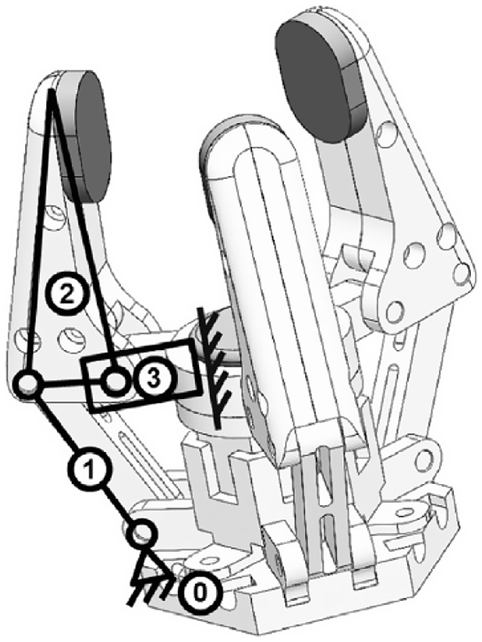
Figure 2. Three-finger handle based on a crank-sliding mechanism.
This mechanism is widely applied to capture various objects. It is necessary to achieve a high degree of reliability for aliquoting tasks. To do this, it is necessary to reduce the number of moving elements. Capturing a similar configuration (Fig. 3) is described in one of the patents [Reference Belyaev21]. A worm gear is applied in this gripper to ensure that the levers are closed. However, the proposed scheme has four joints for each gripper lever (finger). This negatively affects the smoothness and reliability of the system.

Figure 3. Prototype of a gripping device.
This gripper was chosen as the prototype of a new gripping device. The number of rotational joints in each finger has been reduced from four to one. At the same time, the number of fingers is increased to three for gripping the test tube in the upper part. The clenching and unclenching of the fingers are provided due to the radial trajectory of movement (Fig. 4(a)).

Figure 4. (a) Diagram of the developed sample. 1 - Radius of rotation of the lever, 2 - lever, 3 - rotary joint, 4 - axis of rotation, 5 - spherical part of the lever, 6 - globoid worm, 7 - mechanism base, 8 - spring, 9 - position of the lever when the spring is compressed. (b) Globoid worm.
The system works as follows: The engine drives a triple globoid worm. The spherical part of the lever moves along the helical surface of the globoid and rotates the lever relative to the joint along an arc of a circle. The lever is secured to the base of the mechanism by means of a rotational joint. The spherical part of the lever is pressed against the helical surface of the globoid due to the spring. The spherical part of the lever moves along the helical surface of a triple globoid worm. The gripping device provides gripping as a result of the radial movement of the lever along the path 1 (Fig. 4(a)).
An analog of a globoid grip is a well-known transmission mechanism – a globoid gear transmission (Fig. 4(b)). This type of transmission is applied to transfer rotary motion between crossing shafts. Globoid transmission will provide the necessary force, smoothness and reliability of the gripper, and this is due to the worm gear device.
The globoid transmission ensures the transmission of significant torques, which will provide reliable holding with a relatively low cost of drive energy and small dimensions. However, in the case of the developed gripper, this is not required, so a simpler surface is applied instead of a gear wheel. Let’s define the main parameters of the proposed globoid worm in accordance with the scheme (Fig. 5).

Figure 5. Calculation scheme of the globoid transmission.
The main parameters of the globoid transmission, such as half the pitch diameter of the pin:
 \begin{equation} r_{A}=r_{a 2}-2 h_{a 2}=S-\frac{d_{1}}{2} \end{equation}
where
 $r_{a2}$
is the radius of rotation of the lever,
$r_{a2}$
is the radius of rotation of the lever,
 $h_{a2}$
is the height of the pitch diameter from the base of the helical surface,
$h_{a2}$
is the height of the pitch diameter from the base of the helical surface,
 $S$
is the center distance, and
$S$
is the center distance, and
 $d_1$
is the minimum pitch diameter of the globoid;
$d_1$
is the minimum pitch diameter of the globoid;
 $C=S-0.1h_{a2}$
– minimum radial clearance;
$C=S-0.1h_{a2}$
– minimum radial clearance;
 $R_{a1}=S-0.5d_{a1}$
, the radius of the vertices of the worm turns in the axial plane, where
$R_{a1}=S-0.5d_{a1}$
, the radius of the vertices of the worm turns in the axial plane, where
 $d_{a1}$
is the minimum globoid diameter and is defined as
$d_{a1}$
is the minimum globoid diameter and is defined as
 $d_{a1}=d_1+2h_{a2}$
;
$d_{a1}=d_1+2h_{a2}$
;
 $R_{}=r_{a2}+C$
, the radius of the globoid worm depressions in the axial plane.
$R_{}=r_{a2}+C$
, the radius of the globoid worm depressions in the axial plane.

Figure 6. Calculation scheme.
The height of the globoid depends on the angle
 $\alpha$
(Fig. 6). An increase in the
$\alpha$
(Fig. 6). An increase in the
 $\alpha$
angle of deflection of the lever leads to an increase in the height of the globoid. The friction force arises between the lever and the helical surface of the globoid when the globoid gear rotates. The contact patch is a point, not a curve, because of the radial clearance
$\alpha$
angle of deflection of the lever leads to an increase in the height of the globoid. The friction force arises between the lever and the helical surface of the globoid when the globoid gear rotates. The contact patch is a point, not a curve, because of the radial clearance
 $C$
. The frictional force has a significant effect on the performance of the gripper and is calculated by the formula:
$C$
. The frictional force has a significant effect on the performance of the gripper and is calculated by the formula:
 \begin{equation} F_{\mu A}=\mu N_{A} \cos \beta \end{equation}
where
 $\mu$
is the coefficient of friction taken from 0.2 to 0.6 depending on the roughness of the helical surface,
$\mu$
is the coefficient of friction taken from 0.2 to 0.6 depending on the roughness of the helical surface,
 $N_A$
is the force exerting pressure on the helical surface of the globoid, which is directed tangentially relative to
$N_A$
is the force exerting pressure on the helical surface of the globoid, which is directed tangentially relative to
 $r_A$
. In this case,
$r_A$
. In this case,
 $N_A$
can be determined by the formula:
$N_A$
can be determined by the formula:
 \begin{equation} N_{A}=N_{B} \frac{r_{B}}{r_{A}} \end{equation}
where
 $r_B$
is the radius (distance) of the spring and
$r_B$
is the radius (distance) of the spring and
 $N_B$
is determined by the formula:
$N_B$
is determined by the formula:
 \begin{equation} N_{B}=-k\!\left (\left (\sqrt{\left (-r_{B}-x_{P}\right )^{2}+\left (r_{B}-y_{P}\right )^{2}}\right )-\right. \left .\left (\sqrt{\left (-r_{B} \sin \alpha -x_{P}\right )^{2}+\left (r_{B} \cos \alpha -y_{P}\right )^{2}}\right )\right ) \!\sin a \end{equation}
where
 $k$
is the coefficient of elasticity of the spring and
$k$
is the coefficient of elasticity of the spring and
 $x_P$
and
$x_P$
and
 $y_P$
are the coordinates of the point p relative to the center
$y_P$
are the coordinates of the point p relative to the center
 $O$
. The spring in the mechanism is required to ensure a constant tension of the gripper. The spring is stretched when the angle
$O$
. The spring in the mechanism is required to ensure a constant tension of the gripper. The spring is stretched when the angle
 $\alpha$
changes. The angle
$\alpha$
changes. The angle
 $\alpha$
takes values from 10 to 100 degrees, and this is due to the fact that the radius of the outer surface of the globoid is limited by a segment of the circle equal to
$\alpha$
takes values from 10 to 100 degrees, and this is due to the fact that the radius of the outer surface of the globoid is limited by a segment of the circle equal to
 $90^{\circ }$
.
$90^{\circ }$
.
Consider a gripper with n levers. It is necessary to provide a moment greater than the resistance force of the mechanisms to rotate the globoid. To do this, we determine the minimum torque using the following formula:
 \begin{equation} M_{1}=\frac{F_{\mu A} n P_{g}}{2 \pi\eta } \end{equation}
where
 $\eta$
efficiency, taken for the worm gear 0.8,
$\eta$
efficiency, taken for the worm gear 0.8,
 $P_g$
pitch of the helical surface of the globoid, which can be found by the formula
$P_g$
pitch of the helical surface of the globoid, which can be found by the formula
 \begin{equation} P_{g}=2 \pi d \tan \beta \end{equation}
where
 $d$
is the diameter of the globoid, which can be found by the formula
$d$
is the diameter of the globoid, which can be found by the formula
 \begin{equation} d=2\!\left (S-r_{A} \sin \alpha \right ) \end{equation}
Due to the curvature of the surface, the diameter of the globoid decreases from the base to the center and increases from the center to the upper end. In order to maintain a constant step value, it is necessary to change the angle of the helical surface according to the following relationship
 \begin{equation} \text{tg} \beta =\frac{P_{g}}{2 \pi 2\!\left (S-r_{A} \sin \alpha \right )} \end{equation}
Thus, taking into account formulas 2– 7, the torque of the engine can be determined by the formula
 \begin{equation} M_{1}=\frac{F_{\mu A} n 2\!\left (S-r_{A} \sin \alpha \right )\! \tan \beta }{\eta } \end{equation}
In order for the grip to ensure the retention of the tube, it is necessary to take into account the compressive force on each grip finger. The condition under which the tube is held by the gripper can be defined as
 \begin{equation} n F_{\mu C}=G_{C} \end{equation}
where
 \begin{equation} G_{C}=m g \end{equation}
where
 $m_C$
is the mass of the test tube with liquid and g is the force of gravity.
$m_C$
is the mass of the test tube with liquid and g is the force of gravity.
The frictional force that arises as a result of the closing of the gripper fingers is determined by the formula
 \begin{equation} F_{\mu C}=\mu _{C} N_{C} \cos \gamma \end{equation}
where
 $r_C$
is the radius of rotation of the finger,
$r_C$
is the radius of rotation of the finger,
 $N_C$
is the closing force of the gripper fingers,
$N_C$
is the closing force of the gripper fingers,
 $\mu _C$
is the coefficient of friction of the finger against the test tube, for glass and plastic we take from 0.2 to 0.5.
$\mu _C$
is the coefficient of friction of the finger against the test tube, for glass and plastic we take from 0.2 to 0.5.
To determine the dependence of the gripping force on the diameter of the tube, it is necessary to express the angle of application of the force in accordance with Fig. 6. The angle is equal to:
 \begin{equation} \cos \gamma =\sqrt{1-\left (\frac{S-0.5 D}{r_{C}}\right )^{2}} \end{equation}
where
 $D$
is the diameter of the test tube.
$D$
is the diameter of the test tube.
The ratio of the force transmitted from the globoid to the gripping finger can be determined by
 \begin{equation} N_{C}=\frac{N_{M} r_{A}}{r_{C}} \end{equation}
where
 $N_M$
is the force acting on the lever as a result of the globoid rotation.
$N_M$
is the force acting on the lever as a result of the globoid rotation.
Based on Eqs. (10)–(14), we express the force required to hold the test tube by the grip
 \begin{equation} N_{M}=\frac{m g r_{C}}{n \mu _{C} r_{A} \sqrt{1-\left (\frac{S-0.5 D}{r_{C}}\right )^{2}}} \end{equation}
Therefore, the minimum motor torque for capturing the tubes can be determined by the formula
 \begin{equation} M=\frac{2 n\left (N_{M}+F_{\mu A}\right )\!\left (S-r_{A} \sin \alpha \right )\! \tan \beta }{\eta } \end{equation}
The design-in-context method is applied to develop a capture prototype. To do this, add the robot model to the modeling workspace, and then, using its dimensions, develop a gripper prototype as shown in Fig. 7.

Figure 7. Creating the gripper housing. (a) Developing the flange, (b) pulling the housing, (c) developing the housing pockets.
The body of the gripper is designed to remain stationary relative to the end-effector of the robot. The inlet link of the gripper is divided into two elements as shown in Fig. 8. The first part is a flange with a rigidly fixed screw, and the second part is a globoid with a threaded hole inside.

Figure 8. Gripper input link, (a) flange, (b) globoid surface.
The creation of the surface of the globoid largely depends on the height and radius of curvature [Reference Tanaka, Ogawa, Nakamoto, Sonoura and Eto22]–[Reference Fontanelli, Ficuciello, Villani and Siciliano25], as can be seen from formulas (2)–(7) and (13). The curvature of the surface was determined based on the trajectory of the lever movement and was 30 mm. The height of the globoid provides a deflection angle of the capture within 100 degrees. The development of the globoid was carried out graphically using the Computer Aided Design (CAD) system as follows (Fig. 9):

Figure 9. Graphic process of constructing a globoid, (a) sketch of a curved trajectory, (b) division of the globoids into parts of equal height, (c) creation of a curved surface.
-
(1) set the height of the initial cylinder based on the required curvature,
-
(2) develop a globoid with the required radius (Fig. 9(a)),
-
(3) divide the surface into 10 segments equal in height and depending on the required step, we build on each of them a point offset from the previous one by the required angle and connect the points (Fig. 9(b))
-
(4) develop a screw of the required profile using the resulting trajectory (Fig. 9(c))
As a result, a 3D capture model was developed (Fig. 10) according to which a layout was made using 3D printing (Fig. 11).

Figure 10. 3D model of the gripper device.

Figure 11. Mockup motion frames, (a), (b), (c) capture motion sequence.
The article proposes a schematic and technical solution of a gripper, which is necessary for aliquoting biological material. In the proposed configuration (Fig. 12), two modules of different topologies are used. The first is a parallel DeLi manipulator based on a delta robot. It has four degrees of freedom and an end-effector in the form of a dispenser, which provides the basic operations of liquid transfer. The second is the Uni module based on a serial collaborative robot for handling plate and tube transport operations. Stationary manipulator Uni is based on a serial robot with six rotary joints and a gripper.

Figure 12. A robotic system for aliquoting biological material.
The RS includes: housing 1, which contains a parallel manipulator 2. The parallel manipulator moves the dispenser 3, which aliquots the biomaterial. It has a replaceable tip 4. The serial 6-DoF Uni robot is stationary on a fixed base 6 and provides lifting of racks with test tubes 7. The racks are lifted using a specialized gripper designed for loading and unloading racks with test tubes within the working area 8. The aliquot process takes place in the working area.
The gripper is driven by the rotation of the last drive rotational joint of the Uni robot. The gripper allows the movement of tubes within the working area of the robot. Medical blood sample tubes were used for the experiment. The tubes are half filled with liquid to approximate the actual mass (Fig. 13).

Figure 13. Moving test tubes with liquid.
An experiment was conducted to assess the repeatability. To do this, a program was written in which the manipulator performed the opening and closing of the fingers before and after the load. At each moment of stopping shooting in the extreme position, photographs of his position were taken by a camera on a tripod. Images were obtained, which were subsequently superimposed on each other with a transparency effect (Fig. 14). This made it possible to determine the position of the points of the same name during each finger compression cycle. The distance between the points was circled by a circle of the corresponding diameter. There are points in the photo that go beyond the boundaries of the designated circles, but in these photos there was a displacement of the entire gripper device, which is due to the deformation of the plastic case. The offset points were also evaluated taking into account the X offset error. Thus, conclusions were drawn about the repeatability of the gripper device, which was no more than 1.1 mm.

Figure 14. Repeatability assessment.
The curved surface of the globoid determines the angle of deviation of the grip fingers from the closed to the open position. Then the pitch and the number of turns of the helical surface of the globoid determine the closing speed of the gripping fingers. In the layout, the parameters are selected at which the pitch of the helical surface of the globoid is equal to the height of the curved surface and has one turn, then one rotation of the motor shaft is required to close the grip fingers. The end-effector of the robot makes 30 revolutions per minute, which corresponds to the closing of the fingers of the grip in 2 seconds. At the same time, the minimum distance between the tubes with biological fluid for the safe operation of the gripper device, taking into account the repeatability of the manipulator, was 38 mm. This value was determined as the radius of the hole into which the manipulator should get with a gripper device with open fingers to grab a test tube with a diameter of 15 mm.
From the point of view of grip stability, the gripper device is optimally designed to perform a narrowly focused task. There is a metric describing the reliability of the gripper device [Reference Sato and Yoshikawa26]. The magnitude of the force at the capture points is always the same due to the simultaneous movement of the fingers and the features of the globoidal transmission. The manipulator will always grab a laboratory test tube standing on a tripod, and therefore the points of application of force will be evenly distributed over the surface of the cylinder at an equal distance. At the same time, the gripping fingers have cylindrical grooves that facilitate the centering of the test tube when closing the fingers. An increase in the contact points would have a positive effect on the reliability of the grip, but with the addition of one approach, the helical surface of the globoid will significantly increase in diameter. There are factors such as the repeatability of the manipulator, errors in determining the position of the motor shaft, which should be taken into account when designing a motion control system.
4. Results and discussions
The dependence of the angles of deflection of the lever
 $\alpha$
, as well as the angles of approach of the helical surface of the globoid
$\alpha$
, as well as the angles of approach of the helical surface of the globoid
 $\beta$
, on the required engine torque has been investigated.
$\beta$
, on the required engine torque has been investigated.
The initial parameters of the mechanism were selected to reveal the dependence of the deflection of the lever by an angle
 $\alpha$
when turning the globoid. The parameters of the mechanism, selected in accordance with the dimensions of the robot:
$\alpha$
when turning the globoid. The parameters of the mechanism, selected in accordance with the dimensions of the robot:
 $S$
= 21 mm,
$S$
= 21 mm,
 $r_A$
= 12 mm,
$r_A$
= 12 mm,
 $r_B$
= 6 mm. The ratio
$r_B$
= 6 mm. The ratio
 $r_A/r_B = 2/1$
, the height of the sliding body
$r_A/r_B = 2/1$
, the height of the sliding body
 $h_{a2}$
= 0.1 mm, the pitch of the helical surface of the globoid
$h_{a2}$
= 0.1 mm, the pitch of the helical surface of the globoid
 $P_g$
=16 mm, and the coordinates
$P_g$
=16 mm, and the coordinates
 $x_P$
= 3 mm,
$x_P$
= 3 mm,
 $y_P$
= 12 mm are chosen arbitrarily. The coefficient
$y_P$
= 12 mm are chosen arbitrarily. The coefficient
 $k$
is assumed to be 5. The roughness of the surface during 3D printing of the layout is Ra 3.2; therefore, the coefficient of friction
$k$
is assumed to be 5. The roughness of the surface during 3D printing of the layout is Ra 3.2; therefore, the coefficient of friction
 $\mu$
is assumed to be 0.3.
$\mu$
is assumed to be 0.3.
The effect of spring elasticity k on the force of spring action
 $N_B$
is shown in Fig. 15(d). The spring elasticity index should be minimized; however, the plastic joint of the layout does not allow to effectively press the lever at low values. Based on this, values with an equal step from 3 to 7 n were selected, while an average value of 5 n was selected for calculating other parameters in Table II.
$N_B$
is shown in Fig. 15(d). The spring elasticity index should be minimized; however, the plastic joint of the layout does not allow to effectively press the lever at low values. Based on this, values with an equal step from 3 to 7 n were selected, while an average value of 5 n was selected for calculating other parameters in Table II.
Table II. Summary table of calculation parameters.


Figure 15. Graph of the dependence of the coefficient of elasticity on the force of the spring action.
Thus, as the angle
 $\alpha$
increases, the pressure on the globoid also increases, thereby increasing the friction between the lever and the sliding surface of the globoid (Fig. 16(a)). This is due to the fact that with an increase in the angle
$\alpha$
increases, the pressure on the globoid also increases, thereby increasing the friction between the lever and the sliding surface of the globoid (Fig. 16(a)). This is due to the fact that with an increase in the angle
 $\alpha$
, the elongation of the spring also increases, thereby increasing the elastic force
$\alpha$
, the elongation of the spring also increases, thereby increasing the elastic force
 $F_{\mu A}$
.
$F_{\mu A}$
.

Figure 16. Influence of the angles
 $\alpha$
and
$\alpha$
and
 $\beta$
on the calculation system, (a) the friction force depending on the angle of rotation of the lever, (b) the friction force depending on the angle of approach of the helical surface of the globoid.
$\beta$
on the calculation system, (a) the friction force depending on the angle of rotation of the lever, (b) the friction force depending on the angle of approach of the helical surface of the globoid.
The linear increase in friction depending on the rotation of the angle
 $\alpha$
is associated with an increase in the force of action of the spring during tension, so it can be argued that it is the compression spring, and not the tension spring, that will be most effective. This will reduce the friction at the time of holding the tube, while increasing the grip when opening.
$\alpha$
is associated with an increase in the force of action of the spring during tension, so it can be argued that it is the compression spring, and not the tension spring, that will be most effective. This will reduce the friction at the time of holding the tube, while increasing the grip when opening.
At the same time, at different angles
 $\beta$
of the globoid surface, there is a change in the friction force 2 (Fig. 16(b)). It was determined that the friction force
$\beta$
of the globoid surface, there is a change in the friction force 2 (Fig. 16(b)). It was determined that the friction force
 $F_{(\mu A)}$
changes depending on the deflection angle of the lever
$F_{(\mu A)}$
changes depending on the deflection angle of the lever
 $\alpha$
. The moment
$\alpha$
. The moment
 $M_1$
on the motor shaft required for the movement of the mechanism takes the values shown in Fig. 17.
$M_1$
on the motor shaft required for the movement of the mechanism takes the values shown in Fig. 17.

Figure 17. Graph of the moment at different angles
 $\alpha$
and
$\alpha$
and
 $\beta$
.
$\beta$
.
Let us calculate the minimum motor torque for gripping the tubes depending on their diameter using formulas (10)–(16). We take the coefficient
 $\mu$
equal to
$\mu$
equal to
 $\mu$
= 0.5. The calculation results are presented in Table III.
$\mu$
= 0.5. The calculation results are presented in Table III.
Table III. Summary table of calculation parameters.

A feature of the proposed grip is that when the diameter of the grasped object changes, the angle of action of the force of pressing the finger changes Fig. 14. The dependence shown in Fig. 18 means that for a gripper of this type, there are optimal parameters of the objects for gripping. The optimal parameters will change depending on the dimensions of the gripper; for the calculated gripper, the optimal diameter is 10 mm.

Figure 18. Dependence of the required torque on the diameter of the object.
The developed gripping device allows to work with robots of the universal series without using an engine and control devices. Rotation of the end-effector of the robot is sufficient to control the capture. This could simplify the design of the gripping device presented in the article [Reference Russo20], where the authors use an additional motor in the design of the gripping device to grab and move vegetables using the universal robot. Collaborative work is often able to determine the load on the links, which can also be used to control the compression force.
5. Conclusions
The tube gripper is an essential element of a robotic aliquot system. Such a development will allow eliminating the human factor in the process of aliquoting biological liquid and increasing the safety of laboratory staff. The calculations made it possible to reveal the dependences of the forces acting in the given configuration of the gripper. The minimum moment required to set the system in motion and the moment required to grip the tube have been determined. The required torque on the gripper motor shaft for the gripper is 0.137
 ${\rm N}\cdot {\rm mm}$
. The dependence of the angle of the helical surface and its pitch is determined. The layout of the gripper has been obtained using 3D printing. The performance of the proposed kinematic system based on the globoid has been experimentally proved. The gripper based on the globoid has a simple kinematic structure and can be applied in various industries. The results of the repeatability assessment equal to 1.1 mm can be considered an excellent indicator for the layout, but a more detailed study should be carried out when using less deformable materials such as aluminum. The use of a spring to press the lever against the surface of the screw creates increased friction in the transmission, which can negatively affect grippers with a long working cycle or high closing speed. The dynamic characteristics of the gripping devices were not taken into account, since the nature of the movements is smooth and has a low, little-changing speed. Future developments include a malleable finger component and feedback motion control, as well as friction optimization through the use of a lubricant or a material with a lower coefficient of friction.
${\rm N}\cdot {\rm mm}$
. The dependence of the angle of the helical surface and its pitch is determined. The layout of the gripper has been obtained using 3D printing. The performance of the proposed kinematic system based on the globoid has been experimentally proved. The gripper based on the globoid has a simple kinematic structure and can be applied in various industries. The results of the repeatability assessment equal to 1.1 mm can be considered an excellent indicator for the layout, but a more detailed study should be carried out when using less deformable materials such as aluminum. The use of a spring to press the lever against the surface of the screw creates increased friction in the transmission, which can negatively affect grippers with a long working cycle or high closing speed. The dynamic characteristics of the gripping devices were not taken into account, since the nature of the movements is smooth and has a low, little-changing speed. Future developments include a malleable finger component and feedback motion control, as well as friction optimization through the use of a lubricant or a material with a lower coefficient of friction.
Acknowledgments
This work was supported by the state assignment of Ministry of Science and Higher Education of the Russian Federation under Grant FZWN-2020-0017.
Author contributions
AV writing initial draft, review and editing, conceptualization, metodology and investigation. VC review and editing, conceptualization, validation and formal analizys. LR reviewand editing, conceptualization, project administration, supervision, funding acquisition and investigation. GC project administration, supervision, review and editing, funding acquisition, and methodology.
Conflict of interest
The authors declare that they have no conflict of interest.
Ethical considerations
None


