


I. INTRODUCTION
Three polymorphs of LiMSO4F fluorosulfates crystallize in triplite (M = Fe and Mn; monoclinic, C2/c) (Ati et al., Reference Ati, Melot, Chotard, Rousse, Reynaud and Tarascon2011, Reference Ati, Sathiya, Boulineau, Reynaud, Abakumov, Rousse, Melot, Van Tendeloo and Tarascon2012a; Barpanda et al., Reference Barpanda, Ati, Melot, Rousse, Chotard, Doublet, Sougrati, Corr, Jumas and Tarascon2011a; Tripathi et al., Reference Tripathi, Popov, Ellis, Huq and Nazar2012, Reference Tripathi, Popov, Sun, Ryan and Nazar2013; Lee and Park, Reference Lee and Park2014; Kim et al., Reference Kim, Jung and Kang2015; Kim and Kang, Reference Kim and Kang2017), tavorite (M = Fe, Co, Ni, and Mg; triclinic,
 $\bar P$
) (Sebastian et al., Reference Sebastian, Gopalakrishnan and Piffard2002; Ati et al., Reference Ati, Walker, Djellab, Armand, Recham and Tarascon2010; Salanne et al., Reference Salanne, Marrocchelli and Watson2012; Tripathi et al., Reference Tripathi, Popov, Ellis, Huq and Nazar2012; Jalem et al., Reference Jalem, Nakayama and Kasuga2014; Sobkowiak et al., Reference Sobkowiak, Roberts, Häggström, Ericsson, Andersson, Edström, Gustafsson and Björefors2014; Eriksson et al., Reference Eriksson, Sobkowiak, Ångström, Sahlberg, Gustafsson, Edström and Björefors2015), and sillimanite (M = Zn; orthorhombic, Pnma) (Barpanda et al., Reference Barpanda, Chotard, Delacourt, Reynaud, Filinchuk, Armand, Deschamps and Tarascon2011b; Tripathi et al., Reference Tripathi, Popov, Ellis, Huq and Nazar2012) structures. They are being extensively explored for using as cathodes (M = Fe, Mn, Co, and Ni) and electrolytes (M = Zn and Mg) in Li-ion batteries. Their solid solutions (Barpanda et al., Reference Barpanda, Recham, Chotard, Djellab, Walker, Armand and Tarascon2010, Reference Barpanda, Ati, Melot, Rousse, Chotard, Doublet, Sougrati, Corr, Jumas and Tarascon2011a; Ramzan et al., Reference Ramzan, Lebègue and Ahuja2010; Cai et al., Reference Cai, Chen, Xu, Du, Li, Meng, Wang and Wei2011; Radha et al., Reference Radha, Furman, Ati, Melot, Tarascon and Navrotsky2012; Tripathi et al., Reference Tripathi, Popov, Ellis, Huq and Nazar2012) adopt one of three isostructures or just mixed phases varying with compositions and synthesis conditions.
$\bar P$
) (Sebastian et al., Reference Sebastian, Gopalakrishnan and Piffard2002; Ati et al., Reference Ati, Walker, Djellab, Armand, Recham and Tarascon2010; Salanne et al., Reference Salanne, Marrocchelli and Watson2012; Tripathi et al., Reference Tripathi, Popov, Ellis, Huq and Nazar2012; Jalem et al., Reference Jalem, Nakayama and Kasuga2014; Sobkowiak et al., Reference Sobkowiak, Roberts, Häggström, Ericsson, Andersson, Edström, Gustafsson and Björefors2014; Eriksson et al., Reference Eriksson, Sobkowiak, Ångström, Sahlberg, Gustafsson, Edström and Björefors2015), and sillimanite (M = Zn; orthorhombic, Pnma) (Barpanda et al., Reference Barpanda, Chotard, Delacourt, Reynaud, Filinchuk, Armand, Deschamps and Tarascon2011b; Tripathi et al., Reference Tripathi, Popov, Ellis, Huq and Nazar2012) structures. They are being extensively explored for using as cathodes (M = Fe, Mn, Co, and Ni) and electrolytes (M = Zn and Mg) in Li-ion batteries. Their solid solutions (Barpanda et al., Reference Barpanda, Recham, Chotard, Djellab, Walker, Armand and Tarascon2010, Reference Barpanda, Ati, Melot, Rousse, Chotard, Doublet, Sougrati, Corr, Jumas and Tarascon2011a; Ramzan et al., Reference Ramzan, Lebègue and Ahuja2010; Cai et al., Reference Cai, Chen, Xu, Du, Li, Meng, Wang and Wei2011; Radha et al., Reference Radha, Furman, Ati, Melot, Tarascon and Navrotsky2012; Tripathi et al., Reference Tripathi, Popov, Ellis, Huq and Nazar2012) adopt one of three isostructures or just mixed phases varying with compositions and synthesis conditions.
The fluorosulfate family is explored because of the following reasons. (a) The popular olivine LiFePO4 phosphate has a redox potential of 3.45 V (Padhi et al., Reference Padhi, Nanjundaswamy and Goodenough1997) and ionic conductivity of 2 × 10⁻⁹ S cm−1 at 147 °C with one-dimensional (1D) Li-ion diffusion (Amin et al., Reference Amin, Balaya and Maier2007). To increase the ionic conductivity and alter dimensionality of Li+ transport in this cathode material, the fluoride anion is incorporated to produce a 3D tavorite LiFePO4F fluorophosphate (2.8 V; 0.6–5.4 × 10⁻⁷ S cm−1 at 27–50 °C) (Ramesh et al., Reference Ramesh, Lee, Ellis and Nazar2010; Prabu et al., Reference Prabu, Reddy, Selvasekarapandian, Rao and Chowdari2012; Chen et al., Reference Chen, Shao, Li, Zhao, Li, Liu, Gao and Zhang2014). (b) Two methods are induced to compensate the unfavorable decrease of potential. The first is using other redox couple with a higher potential (e.g. V3+/V4+, 4.2 V) to replace Fe2+/Fe3+ (Barker et al., Reference Barker, Gover, Burns and Bryan2005). The second is to constitute a different polyanion moiety, e.g. Li2FeSiO4 orthosilicate (3.1 V) (Girish and Shao, Reference Girish and Shao2015) and LiFeSO4F fluorosulfate with the potential of 3.6 V (7 × 10⁻¹¹ S cm−1 at 25 °C and 4 × 10⁻⁶ S cm−1 at 147 °C) for tavorite (Ati et al., Reference Ati, Walker, Djellab, Armand, Recham and Tarascon2010; Recham et al., Reference Recham, Chotard, Dupont, Delacourt, Walker, Armand and Tarascon2010; Yahia et al., Reference Yahia, Lemoigno, Rousse, Boucher, Tarascon and Doublet2012) or 3.9 V for triplite (Ati et al., Reference Ati, Melot, Chotard, Rousse, Reynaud and Tarascon2011, Reference Ati, Sathiya, Boulineau, Reynaud, Abakumov, Rousse, Melot, Van Tendeloo and Tarascon2012a; Barpanda et al., Reference Barpanda, Ati, Melot, Rousse, Chotard, Doublet, Sougrati, Corr, Jumas and Tarascon2011a; Yahia et al., Reference Yahia, Lemoigno, Rousse, Boucher, Tarascon and Doublet2012). The last one displays both the highest potential ever reported for an Fe-based compound, as well as a comparable specific energy (588 Wh/kg) with that of LiFePO4 (587 Wh/kg) (Ati et al., Reference Ati, Sathiya, Boulineau, Reynaud, Abakumov, Rousse, Melot, Van Tendeloo and Tarascon2012a).
The triplite LiMSO4F (M = Fe and Mn) can be synthesized by ambient direct solid-state (Radha et al., Reference Radha, Furman, Ati, Melot, Tarascon and Navrotsky2012; Kim et al., Reference Kim, Jung and Kang2015; Kim and Kang Reference Kim and Kang2017), pressure-controlled solid-state [e.g. autoclave (Ati et al., Reference Ati, Melot, Chotard, Rousse, Reynaud and Tarascon2011; Barpanda et al., Reference Barpanda, Ati, Melot, Rousse, Chotard, Doublet, Sougrati, Corr, Jumas and Tarascon2011a; Ati et al., Reference Ati, Sathiya, Boulineau, Reynaud, Abakumov, Rousse, Melot, Van Tendeloo and Tarascon2012a), vacuum (Liu et al., Reference Liu, Zhang and Huang2011), or vacuum hot-pressing (Dong et al., Reference Dong, Yu, Sun, Liu, Yang and Huang2013)], extended solvothermal (Tripathi et al., Reference Tripathi, Popov, Ellis, Huq and Nazar2012), microwave solvothermal (Tripathi et al., Reference Tripathi, Popov, Sun, Ryan and Nazar2013), spark plasma sintering (Ati et al., Reference Ati, Sathiya, Boulineau, Reynaud, Abakumov, Rousse, Melot, Van Tendeloo and Tarascon2012a), ball-milling (Ati et al., Reference Ati, Sathiya, Boulineau, Reynaud, Abakumov, Rousse, Melot, Van Tendeloo and Tarascon2012a), and ionothermal (Barpanda et al., Reference Barpanda, Ati, Melot, Rousse, Chotard, Doublet, Sougrati, Corr, Jumas and Tarascon2011a) (only for M = Mn) methods. Several unit-cell parameters for triplite LiFeSO4F were reported (Ati et al., Reference Ati, Melot, Chotard, Rousse, Reynaud and Tarascon2011; Tripathi et al., Reference Tripathi, Popov, Ellis, Huq and Nazar2012, Reference Tripathi, Popov, Sun, Ryan and Nazar2013; Kim et al., Reference Kim, Jung and Kang2015; Kim and Kang, Reference Kim and Kang2017). We find till now (dated to October 30, 2017) one Crystallographic Information File (CIF), i.e. ICSD 187799 (Tripathi et al., Reference Tripathi, Popov, Sun, Ryan and Nazar2013), has been deposited in the Inorganic Crystal Structure Database (ICSD), Germany. The corresponding triplite LiFeSO4F was obtained through a microwave solvothermal route in an autoclave using tetraethylene glycol (TEG) as a reaction medium.
In this work, the triplite LiFeSO4F powder was synthesized through an ambient two-step solid-state route. The reaction process analysis, phase determination/refinement, galvanostatic cycling and cyclic voltammetry tests were performed.
II. EXPERIMENTAL
A. Sample preparation
The white FeSO4·H2O powder (labeled as OS150_60) was pre-synthesized by heating commercial FeSO4·7H2O (99+ wt%) at 150 °C for 60 min in argon. Then FeSO4·H2O and LiF (99+ wt%) mixture, with the stoichiometric ratio of LiFeSO4F, was ball-milled with zirconia balls for 2 h in alcohol (99+ wt%), dried at 60 °C for 12 h in vacuum, and formed into pellets. Pellets were kept in alumina crucibles and calcined once or twice in argon. After ball-milling, three series of brownish gray powders were obtained: (i) in a FeSO4·H2O/LiF mole ratio of 1 : 1 for 45 min at different temperatures (400, 450, or 500 °C); (ii) at 450 °C for 45 min in different ratios (1 : 1, 1 : 1.05, or 1 : 1.1 mol%); (iii) at 450 °C in a ratio of 1 : 1.05 in different holding time (45, 45 + 90, or 45 + 225 min), while the last two samples were calcined twice at the same temperature and well ground between. The corresponding samples were thus labeled as S400_45_1.0, S450_45_1.05, and S450_45 + 90_1.05 and so on.
B. Characterization
The reaction process of FeSO4·H2O/LiF (1 : 1, mol%) was studied by TG-DSC-MS (STA 449F3 & QMS403 C Aëolos, Netzsch Co. Ltd, Germany) from room temperature (RT) to 600 °C. Mass spectrometer monitored all of the possible gases such as H2O, SO3, SO2, SO, O2, F2, H2S, and HF. Phase analysis (5° ≤ 2θ ≤ 80°) was carried out by XRD (RU-200B/D/Max-rB, Rigaku Co. Ltd, Japan) at a scan rate of 10°/min. Crystal structure determination (5° ≤ 2θ ≤ 140°) was carried out using CuK α radiation (λ α1 = 1.54060 Å, 40 kV, 40 mA) with a diffractometer (D8 Adv., Bruker Co. Ltd, Germany) in flat plate θ/2θ geometry at 0.0194303°/s. Testing conditions included a divergence slit of 1.0 mm, an antiscatter slit of 7.39 mm, a primary soller slit of 2.5°, a second soller slit of 2.5°, and a detector slit of 12.27 mm. The structure refinement and quantitative analysis of phases were performed by Rietveld method implemented in GSAS/EXIGUI software (Larson et al., Reference Larson and Von Dreele2004) using the model of (Li1, Fe1)8f (Li2, Fe2)8f {S8f [O8f ]4}F8f (Tripathi et al., Reference Tripathi, Popov, Sun, Ryan and Nazar2013). The LiFeSO4F electrode and coin-type cell were prepared using the same method as LiFePO4F (Chen et al., Reference Chen, Shao, Li, Zhao, Li, Liu, Gao and Zhang2014). Galvanostatic cycling was performed between 1.5 and 4.5 V using a CT2001A tester (Wuhan Land Electronics Co., Ltd., China) in a constant-current mode at 0.05 C. Cyclic voltammetry analysis was carried out between 2.0 and 4.5 V vs. Li/Li+ at 0.1 mV s−1 using a CHI660e system (Shanghai Chenhua Instr. Co. Ltd, China).
III. RESULTS AND DISCUSSION
A. Reaction process FeSO4·H2O/LiF mixture
Figure 1 shows TG-DSC and MS spectra of the FeSO4·H2O/LiF mixture from RT to 600 °C. The parallel DSC tests for three times between 420 and 530 °C are shown together. The weight loss of −9.1 wt% ranging from 250 to 350 °C and the endothermic peak at 303 °C [Figure 1(a)], as well as ion current peak of H2O evolving at 292 °C [Figure 1(b)] can be attributed to the loss of H2O from FeSO4·H2O. The rest water was removed at higher temperature which can be seen from the MS result (cf. theoretical loss of −10.6 wt%). At the same time, the tavorite LiFeSO4F (tavorite abbreviated as tav and triplite as tri in the text, see later) forms by a topotactic reaction of FeSO4·H2O with LiF (Ati et al., Reference Ati, Walker, Djellab, Armand, Recham and Tarascon2010).
 $${\rm FeS}{\rm O}_{4} \cdot {\rm H}_{2}{\rm O } + {\rm LiF}\,{\buildrel {303\, ^{\circ}{\rm C, Ar}} \over {{-}\!\!\!{-}\!\!\!{-}\!\!\!{-}\!\!\!{-}\!\!\!{-}\!\!\!{-}\!\!\!\longrightarrow}} {\rm tav}\hbox{-}{\rm LiFeS}{\rm O}_{4}{\rm F} + {\rm H}_{\rm 2}{\rm O} \uparrow $$

Figure 1. (Colour online) TG-DSC (a) and MS (b) spectra of the FeSO4·H2O/LiF mixture in argon from RT to 600 °C. The parallel DSC tests for three times between 420 and 530 °C are shown together.
The endothermic peak around 474–485 °C is corresponding to the thermodynamically favored transformation from tav- to tri-LiFeSO4F. The peaks in parallel tests at 458–462 °C (labeled by question marks) are incognizable for the moment which disappear in the third test [Figure 1(a)].
 $${\rm tav}\hbox{-}{\rm LiFeS}{\rm O}_{4}{\rm F}\,{\buildrel {{474-485}\, ^{\circ}{\rm C, \, Ar}} \over {{-}\!\!\!{-}\!\!\!{-}\!\!\!{-}\!\!\!{-}\!\!\!{-}\!\!\!{-}\!\!\!{-}\!\!\!{-}\!\!\!{-}\!\!\!{-}\!\!\!{-}\!\!\!{-}\!\!\!\longrightarrow}} {\rm tri\hbox{-}LiFeSO}_{4}{\rm F} $$
The calculated configurational enthalpy (Δ H), entropy (Δ S) and free energy change (Δ G) for the tav- to tri-LiFeSO4F transformation are 2.12 ± 0.79 kJ mol−1, 0.01153 kJ mol−1 K−1, and −1.32 ± 0.79 (25 °C)/−6.79 ± 0.79 kJ mol−1 (500 °C), respectively. The positive Δ H means endothermic. The T Δ S arising from disorder is enough to overcome the positive Δ H, thus Δ G becomes more exothermic at higher temperature (vs. RT) to promote synthesis process (Radha et al., Reference Radha, Furman, Ati, Melot, Tarascon and Navrotsky2012).
The tri-LiFeSO4F has been synthesized at 250 °C for 14 days in autoclave (Tripathi et al., Reference Tripathi, Popov, Ellis, Huq and Nazar2012), at 350 °C for 1 h in microwave autoclave (Tripathi et al., Reference Tripathi, Popov, Sun, Ryan and Nazar2013), at 300 °C for 72 h in autoclave (Ati et al., Reference Ati, Melot, Chotard, Rousse, Reynaud and Tarascon2011), and at 400 °C for 1 h by a direct solid-state approach (Kim et al., Reference Kim, Jung and Kang2015; Kim and Kang, Reference Kim and Kang2017). Considering the thermodynamical, kinetic, and synthetic condition within experimental error, the deductive transformation temperature around 474–485 °C is reasonable. Based on the TG-DSC-MS analysis, the optimized condition to synthesize highly pure tri-LiFeSO4F in this work is set for two-step calcination.
The endothermic peak around 501–505 °C (−6.9 wt% loss), as well as ion current peaks of SO2 and SO evolving at 506 °C can be attributed to the decomposition of tri-LiFeSO4F.
 $$\eqalign{& {\rm tri\hbox{-}LiFeS}{\rm O}_{\rm 4}{\rm F} \,{\buildrel {{501}\, ^{\circ}{\rm C,\, Ar}} \over {{-}\!\!\!{-}\!\!\!{-}\!\!\!{-}\!\!\!{-}\!\!\!{-}\!\!\!{-}\!\!\!\longrightarrow}} \displaystyle{{{\rm 3} - {\rm} x} \over {{\rm 12}}}{\rm F}{\rm e}_{\rm 2}{\rm (S}{\rm O}_{\rm 4}{\rm )}_{\rm 3}{\rm} + \displaystyle{{{\rm 3} + x} \over {{\rm 12}}}{\rm F}{\rm e}_{\rm 2}{\rm O}_{\rm 3} \cr \quad & + {\rm LiF} + \displaystyle{x \over {\rm 2}}{\rm SO}_{\rm 2} \uparrow + \displaystyle{{1 - x} \over {\rm 4}}{\rm SO} \uparrow (0 \lt x \le 1)} $$
If decomposition were completed, the weight loss would be −18.0 wt%. The “SO” is not a stable product that its appearance is most likely the result of fragmentation in MS (Ati et al., Reference Ati, Walker, Djellab, Armand, Recham and Tarascon2010). The analysis result does not appear to be affected whether there was “SO” released.
The endothermic peak at 546 °C corresponds to the eutectic temperature of Fe2(SO4)3/LiF mixture, considering that their melting points are 480 °C and 845 °C, respectively. The latter is usually used as a component of molten salts. The ion current peaks of SO2 and SO evolving at 565 °C may be because of two kinds of gases releasing continuously in the melt via Eq. (3). The possibility of Fe2(SO4)3 decomposition is excluded considering its thermodynamics (Majzlan et al., Reference Majzlan, Navrotsky, Stevens, Donaldson, Woodfield and Boerio-Goates2005) and no SO3 releases.
MS tests show that there are H2O, SO2, and SO released at high temperature. Gases found or deduced by other researchers such as H2S (Ati et al., Reference Ati, Walker, Djellab, Armand, Recham and Tarascon2010), HF (Ati et al., Reference Ati, Walker, Djellab, Armand, Recham and Tarascon2010), and F2 (Guo et al., Reference Guo, Wei, Zhang, Bie, Zhang, Zhu, Zhang and Chen2014) have not been detected. This means the final reaction products should be highly pure or major tri-LiFeSO4F with tiny Fe2(SO4)3, Fe2O3, and LiF [Eq. (3)].
B. Phase identification and optimization
Figure 2 shows XRD patterns for three series of powders prepared from mixtures of FeSO4·H2O (pre-synthesized from FeSO4·7H2O) and LiF in different conditions. Powders of Serie iii were tested at a scan rate of 0.0194303°/s, others at 0.1667°/s (10°/min). Results show that pure FeSO4·H2O (OS150_60) is obtained by calcining FeSO4·7H2O at 150 °C for 60 min in argon. For powders of Serie i [Figure 2(a)], the main phase of tri-LiFeSO4F is obtained using FeSO4·H2O/LiF (1 : 1 mol%) for 45 min at 400, 450, or 500 °C while the minor phase is Fe2O3. The purity of tri-LiFeSO4F in S450_45_1.0 (93 ± 3 wt%) is higher than that in S400_45_1.0 (87 ± 3 wt%) and S500_45_1.0 (85 ± 3 wt%).

Figure 2. (Colour online) XRD patterns for three series of powders prepared from mixtures of FeSO4·H2O (OS150_60) and LiF in different conditions: (i) in a mole ratio of 1 : 1 for 45 min at 400, 450, or 500 °C (S400_45_1.0, S450_45_1.0, and S500_45_1.0); (ii) at 450 °C for 45 min in a ratio of 1 : 1, 1 : 1.05, or 1 : 1.1 (S450_45_1.0, S450_45_1.05, and S450_45_1.1); (iii) at 450 °C in a ratio of 1 : 1.05 for 45, 45 + 90, or 45 + 225 min (S450_45_1.05, S450_45 + 90_1.05, and S450_45 + 225_1.05). Patterns for Serie i are shown in Figure 2(a). Patterns for Series ii and iii are shown in Figure 2(b).
For powders of Serie ii [Figure 2(b)], while synthesizing at 450 °C for 45 min in different ratios (1 : 1, 1 : 1.05, or 1 : 1.1 mol%), adding a little excessive LiF can effectively suppress the decomposition of reaction products [Eq. (3)]. The purity of tri-LiFeSO4F in S450_45_1.05 (97.3 ± 1.5 wt%) is higher than that in S450_45_1.0 (93 ± 3 wt%) and S450_45_1.1 (94 ± 3 wt%).
Two-step solid-state route is then performed at 450 °C in a ratio of 1 : 1.05 in different holding time (45 min, 45 + 90 min, or 45 + 225 min), producing powders of Serie iii [Figure 2(b)]. The last two samples (S450_45 + 90_1.05 and S450_45 + 225_1.05) were calcined twice at the same temperature and well ground between. The sample S450_45 + 90_1.05 attains the highest purity of tri-LiFeSO4F phase (98.1 ± 1.5 wt%) which are better than the two-step synthesized S450_45 + 225_1.05 (96.8 ± 1.5 wt%) and the one-step synthesized S450_45_1.05 (97.3 ± 1.5 wt%).
All of the above samples can match tri-LiFeSO4F well without signal of tavorite. The final reaction products are highly pure or major tri-LiFeSO4F with tiny Fe2O3, Fe2(SO4)3, and LiF (the latter two are amorphous), also confirmed by TG-DSC-MS test. Phases found or deduced by other researchers such as FeSO4 (Liu et al., Reference Liu, Zhang and Huang2011; Kim and Kang, Reference Kim and Kang2017), FeS2 (Recham et al., Reference Recham, Chotard, Dupont, Delacourt, Walker, Armand and Tarascon2010), Li2Fe(SO4)2 (Ati et al., Reference Ati, Sathiya, Boulineau, Reynaud, Abakumov, Rousse, Melot, Van Tendeloo and Tarascon2012a; Kim and Kang, Reference Kim and Kang2017), Li2SO4 (Guo et al., Reference Guo, Wei, Zhang, Bie, Zhang, Zhu, Zhang and Chen2014; Kim et al., Reference Kim, Jung and Kang2015; Kim and Kang, Reference Kim and Kang2017), and Fe3O4 (Kim et al., Reference Kim, Jung and Kang2015; Kim and Kang, Reference Kim and Kang2017) have not been detected in this work.
Compared with the published investigations, this work has its distinctions: (i) shorter time, cf. 14 days (Tripathi et al., Reference Tripathi, Popov, Ellis, Huq and Nazar2012); (ii) simplified equipments, cf. autoclave (Ati et al., Reference Ati, Melot, Chotard, Rousse, Reynaud and Tarascon2011; Tripathi et al., Reference Tripathi, Popov, Ellis, Huq and Nazar2012, Reference Tripathi, Popov, Sun, Ryan and Nazar2013) or microwave (Tripathi et al., Reference Tripathi, Popov, Sun, Ryan and Nazar2013); (iii) none organic reagents, cf. TEG (Tripathi et al., Reference Tripathi, Popov, Ellis, Huq and Nazar2012, Reference Tripathi, Popov, Sun, Ryan and Nazar2013) or 1-ethyl-3-methylimidazolium-bis-trifluoromethylsulfonyl-imide ionic liquid (Ati et al., Reference Ati, Melot, Chotard, Rousse, Reynaud and Tarascon2011); (iv) two-step, carbon-free, and solid-state calcination, cf. one-step with impurities (Kim et al., Reference Kim, Jung and Kang2015) or one-step using sucrose (C12H22O11) and poly-vinylidene fluoride (Kim and Kang, Reference Kim and Kang2017). Particularly, there is one CIF file of tri-LiFeSO4F deposited in ICSD till now (ICSD 187799, dated to October 30, 2017) (Tripathi et al., Reference Tripathi, Popov, Sun, Ryan and Nazar2013). The reported triplite phase was obtained through a microwave solvothermal route in an autoclave using TEG as a reaction medium, being under a more rigorous condition.
C. Structure refinement and electrochemical test
Figure 3 shows the final observed, calculated, and difference profiles of the tri-LiFeSO4F structure (S450_45 + 90_1.05) via Rietveld refinement (see the online supplementary material). The inset shows the magnified section in the range of 35–65°. The Li+-ion migration channels in the directions of [0 1 0] were shown in Figure 4(a) and in the directions of [1 0 1] shown were in Figure 4(b), respectively. Agreement indices (R p, R wp, and R F 2) and goodness-of-fit (χ 2) in different Li/Fe occupancies were shown in Figure 4(c). Table I lists Rietveld refinement parameters of the tri-LiFeSO4F structure. Results show the Rietveld refinement converges with acceptable goodness-of-fit (χ 2 = 1.01) and agreement indices (R p = 1.25%, R wp = 1.61%, R exp = 1.60%, and R F 2 = 13.9%). The fit results do not show any anomalies. The obtained structural and thermal parameters are reasonable and in full accord with ICSD 187799 (Tripathi et al., Reference Tripathi, Popov, Sun, Ryan and Nazar2013), but with some discrepancies to another model (Ati et al., Reference Ati, Melot, Chotard, Rousse, Reynaud and Tarascon2011). The MO4F2 (M = Fe, Li) octahedra are alternatively composed of F–F and O–O atoms. They share edges with each other forming two crystallographically zigzag chains along the directions of [0 1 0] and [1 0 1] (Yahia et al., Reference Yahia, Lemoigno, Rousse, Boucher, Tarascon and Doublet2012). Two chains are connected by sharing F–O edges. The F atoms are in a cis-arrangement, in contrast with the corner-shared tavorite isomorph (trans F−F). The SO4 tetrahedra only share corners with other polyhedral (Chung et al., Reference Chung, Barpanda, Nishimura, Yamada and Yamada2012). The move in the [0 1 0] direction is partly restricted, unlike the tav-LiFeSO4F and resulted in a modest conductivity. There is significant disorder of Li and Fe on two sites [Figure 4(c)], while Li has a preference toward site 2 [0.450(6)−Li1/0.550(6)−Li2] and Fe toward site 1 [0.550(6)−Fe1/0.450(6)−Fe2]. But Li and Fe atoms are distributed in a 50–50 proportion in the tav-LiFeSO4F (Recham et al., Reference Recham, Chotard, Dupont, Delacourt, Walker, Armand and Tarascon2010). The entropy associated with the disordered nature of Li and Fe sites results in triplite being the thermodynamically preferred polymorph of LiFeSO4F (Radha et al., Reference Radha, Furman, Ati, Melot, Tarascon and Navrotsky2012; Tripathi et al., Reference Tripathi, Popov, Ellis, Huq and Nazar2012, Reference Tripathi, Popov, Sun, Ryan and Nazar2013). The intrinsic disorder in the precursor with hydroxyl groups, which decomposes upon solid-state conversion, favors the produce of triplite phase; and two-step calcination favors the transformation for hydroxyl groups to tavorite then to triplite, because it occurs very slowly (Tripathi et al., Reference Tripathi, Popov, Sun, Ryan and Nazar2013).

Figure 3. (Colour online) Final observed (dots), calculated (line), and difference profiles of the tri-LiFeSO4F structure via Rietveld refinement. The inset shows the magnified section in the range of 35–65°.

Figure 4. (Colour online) The Li+-ion migration channels in the directions of [0 1 0] (a) and [1 0 1] (b), respectively. Agreement indices (R p, R wp, and R F 2) and goodness-of-fit (χ 2) in different Li/Fe occupancies (c).
Table I. Rietveld refinement parameters of the tri-LiFeSO4F structure.

Space group: C2/c (No.15); monoclinic; Z = 8; M r = 177.84; ρ cal. = 3.3128 g cm−3.
a = 13.0367(4) Å; b = 6.3976(1) Å; c = 9.8425(6) Å; β = 119.6876(17); V = 713.15(2) Å3.
The voltage plateau on 3.9 V in the initial charge/discharge profile (Figure 5), and a pair of peaks in the differential capacity plot [the inset (a)] and cyclic voltammogram [the inset (b)] around 3.9 V are in good agreement with the Fe2+/Fe3+ redox couple of tri-LiFeSO4F. Results support those reported from charge/discharge profiles and differential capacity plots (Ati et al., Reference Ati, Melot, Chotard, Rousse, Reynaud and Tarascon2011, Reference Ati, Sathiya, Boulineau, Reynaud, Abakumov, Rousse, Melot, Van Tendeloo and Tarascon2012a; Barpanda et al., Reference Barpanda, Ati, Melot, Rousse, Chotard, Doublet, Sougrati, Corr, Jumas and Tarascon2011a; Tripathi et al., Reference Tripathi, Popov, Ellis, Huq and Nazar2012, Reference Tripathi, Popov, Sun, Ryan and Nazar2013; Kim et al., Reference Kim, Jung and Kang2015; Kim and Kang, Reference Kim and Kang2017). The unexpected peak of 3.6 V [the insets (a) and (b)] may belong to the tavorite LiFeSO4F phase (Ati et al., Reference Ati, Walker, Djellab, Armand, Recham and Tarascon2010; Recham et al., Reference Recham, Chotard, Dupont, Delacourt, Walker, Armand and Tarascon2010; Yahia et al., Reference Yahia, Lemoigno, Rousse, Boucher, Tarascon and Doublet2012), even though the XRD had not detected it. Maybe this is because that the cyclic voltammogram test (none reports before) is more sensitive than the XRD. Besides, it seems to exist a trace LiFeSO4F1−x (OH) x phase with a couple centered at 3.3 V [the inset (a)], which could be attributed to the preparation process of powder (Ati et al., Reference Ati, Sougrati, Rousse, Recham, Doublet, Jumas and Tarascon2012b), electrode, and cell with trace water from an external environment (Ati et al., Reference Ati, Walker, Djellab, Armand, Recham and Tarascon2010). Deep research on the relationship among the phase purity, preparation, and electrochemical performance is under proceeding. The triplite has a higher operating potential than the tavorite because its vacancy destabilizing effect of Li+-ion is larger. Under the edge-sharing geometry, the effect occurs because of strong Fe3+···Fe3+ repulsive interaction around the vacancy ( Ati et al., Reference Ati, Sathiya, Boulineau, Reynaud, Abakumov, Rousse, Melot, Van Tendeloo and Tarascon2012a; Chung et al., Reference Chung, Barpanda, Nishimura, Yamada and Yamada2012; Lee and Park, Reference Lee and Park2014).
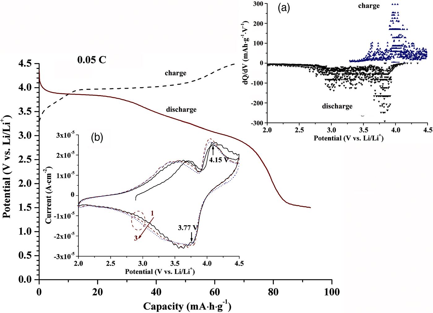
Figure 5. (Colour online) Charge/discharge profile of the tri-LiFeSO4F cell in the first cycle at 0.05 C. The inset (a) and (b) show the corresponding differential capacity plot and cyclic voltammogram in which cycle numbers are indicated, respectively.
IV. CONCLUSIONS
The Rietveld refinement of triplite LiFeSO4F explains the relation of high operating potential and modest conductivity to the structure, which is confirmed by the electrochemical test. The disorder of Li and Fe is also confirmed which is associated with entropy. The latter results in triplite being the thermodynamically preferred polymorph of LiFeSO4F.
SUPPLEMENTARY MATERIAL
The supplementary material for this article can be found at https://doi.org/10.1017/S0885715618000040.
ACKNOWLEDGEMENTS
The authors gratefully acknowledge J.-H. Liu, D. Chen, and B. Li in their group, and Professor B.-L. Wu in GUT. This work was supported by Research Foundation of State Key Laboratory of Advanced Technology for Materials Synthesis and Processing, WUT, China (Grant Nos. 2015-KF-4 and 2016-KF-4).
APPENDIX
Further details of the crystal structure investigation may be obtained from FIZ Karlsruhe–Leibniz Institute for Information Infrastructure, 76344 Eggenstein–Leopoldshafen, Germany (https://www.fiz-karlsruhe.de/en/leistungen/kristallographie/kristallstrukturdepot.html) on quoting the appropriate CSD number (G.-Q. Shao et al., The crystal structure of triplite LiFeSO4F, CSD 432778, 2017.3.20).


