


I. INTRODUCTION
Because of the reconstruction of the existing, 2.3-km-long storage ring PETRA at DESY in Hamburg, one of the most brilliant X-ray sources worldwide will be created (for details see DESY homepage at http://petra3.desy.de). The maximum brilliance will be on the order of 1021 ph/s/mm2/mrad2/0.1% BW with a considerable fraction of coherent photons also in the hard X-ray range.
After the design and approval phase running from 2002 to 2005 the construction work was started in summer 2007 and will be finished in 2009. Figure 1 gives an impression of the new 280-m-long experimental hall from the bird’s eye view.
In the experimental hall a total number of 14 undulator beamlines with up to 30 experimental stations are currently under construction. Table I shows the specification of the new synchrotron source. Within this project the GKSS Research Centre Geesthacht is responsible for the construction and operation of two beamlines, the imaging beamline (IBL) and the high-energy materials science beamline (HEMS).
Studying technological innovations over the last decades it is obvious that prominent developments of novel materials and production technologies are significantly promoted by a fundamental understanding of the materials characteristics, especially the three dimensional inner structures. Characteristic length scales, which influence the structural properties, are often in the range of some micrometers down to a few nanometers (Reimers et al., Reference Reimers, Pyzalla, Schreyer and Clemens2007; Haibel et al., Reference Haibel, Rack and Banhart2006; Berthold et al., Reference Berthold, Haibel, Brandes, Kroh, Gross, Uharek and Schubert2007; Zehbe et al., Reference Zehbe, Haibel and Schubert2006; Beckmann et al., Reference Beckmann, Grupp, Haibel, Huppmann, Nöthe, Pyzalla, Reimers, Schreyer and Zettler2007). Therefore the IBL at PETRA III will be structured into two experimental stations for both microtomography and nanotomography (PETRA III work package site at http://petra3.desy.de/beamlines/work\_packages/e1036/e1551/index\_eng.html).
By means of microtomography the investigation of millimeter sized samples in (sub)-micrometer resolution is planned. The possibility to focus the X-ray beam into the nanometer range will be used for nanotomographic imaging. The X-ray energy range will be tunable between 5 and 50 keV.
II. THE IBL
The imaging beamline is located at an inclined 2×2 m2 undulator section; i.e., the beamline shares the sector with a further beamline. Figure 2 shows the layout of the sector 4 containing both the hard X-ray microprobe and nanoprobe beamline and the imaging beamline.
The sequence of construction on the sector 4 starts from the source with the optics hutch of the microprobe and nanoprobe beamline followed by the optics hutch of the imaging beamline (see colored sections in Figure 2). The next hutch is the nanotomography hutch followed by the microtomography hutch. Both hutches are separated by a two-story control cabin. The microtomography hutch has a maximum distance from the source of 87.5 m. To guarantee a constant temperature and climate inside the experimental hutches in front of both hutches temperature lock rooms are installed. The last both hutches belong to the microprobe and nanoprobe beamline. The control cabin for these hutches is located in front of the microprobe hutch. Both beamlines work independently. The angle between the X-ray tubes is only 5 mrad, so all tomography instruments have to be designed with respect to a second tube near the experiments.
A. Beamline optics
All optical elements, except the collimating X-ray lenses for nanotomography and the coherence diffuser, are located inside of the optics hutch. The main components inside the optics hutch are two nitrogen cooled, alternatively used, fixed exit monochromators. The monochromatization of the

Figure 1. (Color online) Photo of the new PETRA III experimental hall at the DESY area.
X-ray light allows to choose the optimal energy for the investigation objects which depends on the sample thickness and density. A double-crystal monochromator (DCM) made of silicon single crystals (111 and 311) and designed by DESY will be used for tomographic methods, which need a very high monochromatization (Δ E/E≈10−4, e.g., absorption tomography, vector tomography, or diffraction tomography). The cryogenically cooled silicon accepts a total heat load of 400 W at the crystal. For applications, which need particularly high flux (e.g., fast in situ experiments) a double multilayer monochromator equipped with different bent substrates will be used (Δ E/E≈10−2). The multilayer coating is made in house by the GKSS (Störmer et al., Reference Störmer, Michaelsen, Wiesmann, Ricardo and Bormann2006; Störmer et al., Reference Störmer, Häussler, Jäger and Bormann2007; Störmer et al., Reference Störmer, Horstmann, Häussler, Spiecker, Siewert, Scholze, Hertlein, Jäger and Bormann2008). The energy range for both types of monochromators will be tunable between 5 and 50 keV. The cryogenic cooler is located in front of the optics hutch and supplies both monochromators.
B. Microtomography
Due to the small divergence σ x,y even in the low-β mode (see Table I) the half-width of the X-ray beam is very small. Since, for microtomography a sufficient field of view is required, the microtomography hutch is positioned in the largest distance from the source (80 to 87.5 m). At this distance the field of view is sufficient to investigate samples of some millimeters diameter in (sub)-micrometer resolution.
TABLE I. Overview of the design values emittance ε x, particle energy E, normalized emittance ε x/E 2, typical β functions, photon source sizes σ x,y, and divergences σ x,y′ for the new storage ring PETRA III. The photon source parameters are given in RMS values for a photon energy of 12 keV. 2×2 m2 means the inclined undulator (PETRA III homepage at http://petra3.desy.de).
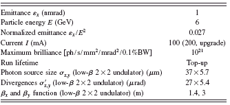

Figure 2. (Color online) Three dimensional impression of the imaging beamline at PETRA III. The beamline is structured into an optics hutch and two experimental stations for different tomographic setups. Both experimental hutch entrances are equipped with temperature lock rooms. The hard X-ray microprobe and nanoprobe beamlines surround the imaging beamline.
In microtomography spatial resolutions in the micrometer range and slightly below can be achieved, so fields of application encompass questions from materials science (e.g., imaging and quantitative analysis of pores, cracks, precipitations, and phase transitions) as well as problems in the area of biology or medicine (e.g., structures of bones, tissues, teeth, and plants).
To achieve such spatial resolutions near the physical limit, it is necessary to assure high mechanical stability for the components of the setup. Figure 3 shows a sketch of the instrument setup.
The experimental setup is composed of three parts, a camera system, a sample stage, and a substructure. Both the camera movement and the sample rotation and translation will run by high precision air bearing stages mounted on granite structures, adjustable in pitch, yaw, roll, and height. The camera system and the sample stage are carried by a granite substructure, which is also adjustable in height, pitch, yaw, roll, and additionally horizontal to the beam. Further,

Figure 3. (Color online) Experimental setup for microtomography at IBL and HEMS.

Figure 4. (Color online) Left: ultracompact piezo positioning system for sample fine adjustment (dismounted and positioned on top of the rotation unit). Right: the sample adjustment unit mounted in the aperture of the high precision rotation stage.
the substructure is able to carry additional equipment, e.g., a detector system like a flat-panel detector for combined tomography and diffraction measurements. The rotation unit of the sample stage is composed of two rotation stages, a high precision stage which carry the samples and a second one, which is positioned around the high precision stage to carry the connecting cables of the sample adjustment unit via sliding contacts (see Figure 4).
For sample fine adjustment five ultracompact, piezo nanopositioners are used, two goniometers and three linear positioners, two for horizontal and one for vertical positioning. The sample adjustment unit is located inside of the aperture of the high precision air bearing rotation stage, in order to minimize the distance between the samples and the rotation axis (see Figure 4), which guarantees extremely low tilt errors of the samples.
The camera microscope optics is a diffraction limited optical system equipped with automated lenses and scintillator changers and slots for apertures, filters, and a fast shutter. The design protects the objectives from radiation damage; the magnification is tunable between β=6 to 50.
To achieve an optimization of instrument efficiency and reliability an automated sample changer will be installed. The sample changer will support up to 40 samples. For in situ measurements several sample environments such as furnaces, tensile/pressure test devices, or climate chambers are under construction (Beckmann et al., Reference Beckmann, Grupp, Haibel, Huppmann, Nöthe, Pyzalla, Reimers, Schreyer and Zettler2007; Grupp et al., Reference Grupp, Henkel, Nöthe, Banhart, Kieback and Haibel2009).
A second microtomography instrument, identical in construction, will be available at the HEMS beamline, also operated by the GKSS Research Centre Geesthacht. Whereas the imaging beamline provides energies in the range between 5 and 50 keV, the energy range of the HEMS beamline starts at 50 keV and ends for tomography about 150 keV; i.e., the HEMS beamline complements the energy range of the IBL toward higher energies.

Figure 5. (Color online) Two concepts for nanotomography. Left: combination of hard X-ray microscopy with tomography. Right: cone beam tomography with nanofocus lenses.

Figure 6. (Color online) Left: refractive X-ray lenses, arranged in series and alternating. Right: SU-8 polymer lenses on a Si wafer.
C. Nanotomography
The nanotomography will be instrumented by using the possibility to focus the X-ray beam into the nanometer range. A separate hutch for nanotomography was constructed at a distance of 62 to 71 m from the source.
One nanotomography setup will be the combination of hard X-ray microscopy with tomography (Schroer and Lengeler, Reference Schroer and Lengeler2005; Schroer et al., Reference Schroer, Benner, Günzler, Kuhlmann, Patommel, Lengeler, Somogyi, Weitkamp, Rau, Snigirev, Snigireva and U.2004a; Lengeler et al., Reference Lengeler, Schroer, Kuhlmann, Benner, Günzler, Kurapova, Zontone, Snigirev, Snigireva, A. S. and Mancini2004; Schroer et al., Reference Schroer, Cloetens, Rivers, Snigirev, Takeuchi and Yun2004b). A sketch of this concept is shown in the left image of Figure 5. The distance inside the nanotomography hutch or even the large distance between both hutches will be used for magnifying the X-ray images. Then, the images will be detected in about a 20-m distance in the microtomography hutch. A second nanotomography setup will use the cone beam geometry (see Figure 5, right). The samples will stand behind the focal point in the cone beam and the magnified radiographic images are detected in an adequate distance from the sample (Snigirev et al., Reference Snigirev, Kohn, Snigireva and Lengeler1996; Snigirev et al., Reference Snigirev, Kohn, Snigireva, Souvorov and Lengeler1998; Grigoriev et al., Reference Grigoriev, Shabelnikov, Yunkin, Snigirev, Snigireva, Di Michiel, Kuznetsov, Hoffmann and Voges2001). The magnification is tunable by changing the distance between the sample and detector. For both methods a spatial resolution below 100 nm is expected for micrometer sized samples.
As X-ray optics we will use refractive X-ray lenses made of SU-8 polymer by a lithographic production process (Last, Reference Last, V., Wallrabe, Tabata and Korvink2009; Reznikova et al., Reference Reznikova, Weitkamp, Nazmov, Last, Simon and Saile2007). The lenses are grouped in arrays with up to 216 lens elements, mounted on Si wafers, and characterized by a high sensitivity, a high transparency, and good chemical and mechanical stability. The apertures of the lenses are in the range between 40 and 500 μm; the radii of curvature are between 5 and 50 μm. They are arranged in rows crossed under 90° in series or alternating (see Figure 6), tilted under 45° and −45° to the substrate. These lenses will be used for asymmetric source compensation and slightly prefocusing in the optics hutch as well as for nanofocusing and magnifying of the radiographic images for the nanotomography experiments.
III. CONCLUSION
After completion of the imaging beamline IBL and the high-energy materials science beamline HEMS at PETRA III four complementary tomography stations will be managed by the GKSS Research Centre at DESY in Hamburg. The HARWI setup for high-energy tomography (16 to 150 keV) and the BW2 setup for tomography at lower energies (6 to 24 keV), both operate at the existing DORIS III synchrotron at DESY, are characterized by a large field of view and an excellent absorption contrast. The tomography facilities at PETRA III (imaging beamline, energy range 5 to 50 keV and HEMS beamline, energy range 50 to 150 keV) differ from the DORIS imaging stations by a high brilliance, high spatial resolution down to the nanometer range and high coherence; i.e., they fulfill excellently the qualifications for phase enhanced and phase contrast tomography, for nanotomography, for high speed or in situ tomography.
ACKNOWLEDGMENTS
We gratefully acknowledge DESY and HASYLAB for developing and providing the infrastructure and the generic optical components as well as for the fruitful discussions.


